


|
|
|
|
|
|
|
|
|
|
|
|
|
|
|
|
|
|
|
|
|
|
|
|
|
|
|
|
|
|
|
|
|
|
|
|
|
|
|
|
|
|
|
|
|
|
|
|
|
|
|
|
|
|
|
|
DISCONTINUED |
|
|
|
|
|
|
|
|
|
|
|
|
|
|
|
|
|
|
|
|
|
|
|
|
|
|
|
|
|
|
|
|
|
|
|
|
|
|
|
|
|
|
|
|
|||||
|
|
|
|
|
|
|
|
|
|
|
|
|
|
|
|
|
|
|
|
|
|
|
|
|
|
|
|
|
|
|
|
|
|
|
|
|
||||||||||||||||
|
|
|
|
PRODUCT |
|
|
|
|
|
|
|
|
|
|
|
|
|
|
|
|
|
|
|
|
|
|
|
|
|
|
|
|
|
|
|
|
|
|
|
|
|
|
|
|
|
|
|
|
||||
|
|
|
|
|
|
|
|
|
|
|
|
AC |
Power |
|
|
Systems |
|
|
|
|
|
|
|
|
|
|
|
|
|
|
||||||||||||||||||||||
|
|
|
|
|
|
|
|
|
|
|
|
|
|
|
|
|
|
|
|
|
|
|
|
|
|
|
|
|
|
|
|
|
|
|
|
|
|
|
|
|
|
|
|
|||||||||
|
|
|
|
|
|
|
|
|
|
|
|
|
|
|
|
|
|
|
|
|
|
|
|
|
|
|
|
For |
|
Business |
|
- |
Critical |
|
|
|
Continuity™ |
|
|
|
|
|
||||||||||
|
|
|
|
|
|
|
|
|
|
|
|
|
|
|
|
|
|
|
|
|
|
|
|
|
|
|
|
|
|
|
|
|
|
|||||||||||||||||||
|
|
|
|
|
|
|
|
|
|
|
|
|
|
|
|
|
|
|
|
|
|
|
|
|
|
|
|
|
|
|
|
|
|
|
|
|
|
|
|
|
|
|
|
|
|
|
|
|
|
|
|
|
|
|
|
|
|
|
|
|
|
|
|
|
|
|
|
|
|
|
|
|
|
|
|
|
|
|
|
|
|
|
|
|
|
|
|
|
|
|
|
|
|
|
|
|
|
|
|
|
|
|
|
|
|
|
|
|
|
|
|
|
|
|
|
|
|
|
|
|
|
|
|
|
|
|
|
|
|
|
|
|
|
|
|
|
|
|
|
|
|
|
|
|
|
|
|
|
|
|
|
|
|
|
|
|
|
|
|
|
|
|
|
|
|
|
|
|
|
|
|
|
|
|
|
|
|
|
|
|
|
|
|
|
|
|
|
|
|
|
|
|
|
|
|
|
|
|
|
|
|
|
|
|
|
|
|
|
|
|
|
|
|
|
|
|
|
|
|
|
|
|
|
|
|
|
|
|
|
|
|
|
|
|
|
|
|
|
|
|
|
|
|
|
|
|
|
|
|
|
|
|
|
|
|
|
|
|
|
|
|
|
|
|
|
|
|
|
|
|
|
|
|
|
|
|
|
|
|
|
|
|
|
|
|
|
|
|
|
|
|
|
|
|
|
|
|
|
|
|
|
|
|
|
|
|
|
|
|
|
|
|
|
|
|
|
|
|
|
|
|
|
|
|
|
|
|
|
|
|
|
|
|
|
|
|
|
|
|
|
|
|
|
|
|
|
|
|
|
|
|
|
|
|
|
|
|
|
|
|
|
|
|
|
|
|
|
|
|
|
|
|
|
|
|
|
|
|
|
|
|
|
|
|
|
|
|
|
|
|
|
|
|
|
|
|
|
|
|
|
|
|
|
|
|
|
|
|
|
|
|
|
|
|
|
|
|
|
|
|
|
|
|
|
|
|
|
|
|
|
|
|
|
|
|
|
|
|
|
|
|
|
|
|
|
|
|
|
|
|
|
|
|
|
|
|
|
|
|
|
|
|
|
|
|
|
|
|
|
|
|
|
|
|
|
|
|
|
|
|
|
|
|
|
|
|
|
|
|
|
|
|
|
|
|
|
|
|
|
|
|
|
|
|
|
|
|
|
|
|
|
|
|
|
|
|
|
|
|
|
|
|
|
|
|
|
|
|
|


 Liebert® GXT2U™


 User Manual - 208V, 2700VA


DISCONTINUED
PRODUCT

TABLE OF CONTENTS
IMPORTANT SAFETY INSTRUCTIONS. . . . . . . . . . . . . . . . . . . . . 1
GLOSSARY OF SYMBOLS . . . . . . . . . . . . . . . . . . . . . . . . . . . . 3
INTRODUCTION . . . . . . . . . . . . . . . . . . . . . . . . . . . . . . . . . . . . 4
MAJOR COMPONENTS. . . . . . . . . . . . . . . . . . . . . . . . . . . . . . . 5
Transient Voltage Surge Suppression and EMI/RFI Filters . . . 5
Rectifier/Power Factor Correction (PFC) Circuit . . . . . . . . . . . . 5
Inverter. . . . . . . . . . . . . . . . . . . . . . . . . . . . . . . . . . . . . . . . . . . . . 5
Battery Charger . . . . . . . . . . . . . . . . . . . . . . . . . . . . . . . . . . . . . . 5
DC-to-DC Converter. . . . . . . . . . . . . . . . . . . . . . . . . . . . . . . . . . . 6
Battery . . . . . . . . . . . . . . . . . . . . . . . . . . . . . . . . . . . . . . . . . . . . . 6
Dynamic Bypass. . . . . . . . . . . . . . . . . . . . . . . . . . . . . . . . . . . . . . 6
Liebert GXT2U—Rear View . . . . . . . . . . . . . . . . . . . . . . . . . . . . 7
INSTALLATION. . . . . . . . . . . . . . . . . . . . . . . . . . . . . . . . . . . . . 8
Preparation. . . . . . . . . . . . . . . . . . . . . . . . . . . . . . . . . . . . . . . . . . 8
Tower UPS Installation . . . . . . . . . . . . . . . . . . . . . . . . . . . . . . . . 8
Rack-Mount UPS Conversion and Installation . . . . . . . . . . . . . 9
External Battery Cabinet Installation . . . . . . . . . . . . . . . . . . . 12
CONTROLS AND INDICATORS. . . . . . . . . . . . . . . . . . . . . . . . . 14
ON/Alarm Silence/Manual Battery Test Button . . . . . . . . . . . 14
Standby/Manual Bypass Button. . . . . . . . . . . . . . . . . . . . . . . . 15
Load/Battery Level Indicators (4 Green, 1 Amber) . . . . . . . . . 15
Fault Indicator LED (Red). . . . . . . . . . . . . . . . . . . . . . . . . . . . . 15
Bypass Indicator LED (Amber) . . . . . . . . . . . . . . . . . . . . . . . . . 15
UPS ON Indicator LED (Green) . . . . . . . . . . . . . . . . . . . . . . . . 15
Battery Indicator LED (Amber) . . . . . . . . . . . . . . . . . . . . . . . . 15
AC Input Indicator LED (Green). . . . . . . . . . . . . . . . . . . . . . . . 15
Output Voltage Selection. . . . . . . . . . . . . . . . . . . . . . . . . . . . . . 16
i |
DISCONTINUED |
|
PRODUCT |
||
|

OPERATING INSTRUCTIONS . . . . . . . . . . . . . . . . . . . . . . . . . . 17
Normal Mode Operation . . . . . . . . . . . . . . . . . . . . . . . . . . . . . . 17 Bypass Mode Operation. . . . . . . . . . . . . . . . . . . . . . . . . . . . . . . 17 Battery Mode Operation . . . . . . . . . . . . . . . . . . . . . . . . . . . . . . 18 Battery Recharge Mode . . . . . . . . . . . . . . . . . . . . . . . . . . . . . . . 18
COMMUNICATIONS . . . . . . . . . . . . . . . . . . . . . . . . . . . . . . . . 19
Communications Interface Port . . . . . . . . . . . . . . . . . . . . . . . . 19 Pins 4 & 5 - Remote Shutdown on Battery. . . . . . . . . . . . . . . . 19 Pins 5 & 6 - Any-Mode Shutdown . . . . . . . . . . . . . . . . . . . . . . . 20
Auto-Enable Output. . . . . . . . . . . . . . . . . . . . . . . . . . . . . . . . . 20 Pin 6 Logic . . . . . . . . . . . . . . . . . . . . . . . . . . . . . . . . . . . . . . . . 20
UPS Intelligent Communications . . . . . . . . . . . . . . . . . . . . . . . 21
CONFIGURATION PROGRAM . . . . . . . . . . . . . . . . . . . . . . . . . 22
Liebert GXT2U Configuration Program Abilities . . . . . . . . . . 22
What You Will Need . . . . . . . . . . . . . . . . . . . . . . . . . . . . . . . . 22
MAINTENANCE . . . . . . . . . . . . . . . . . . . . . . . . . . . . . . . . . . . 23
Battery Replacement . . . . . . . . . . . . . . . . . . . . . . . . . . . . . . . . . 23
Internal Battery Replacement Procedures . . . . . . . . . . . . . . . 24
TROUBLESHOOTING . . . . . . . . . . . . . . . . . . . . . . . . . . . . . . . 25
SPECIFICATIONS . . . . . . . . . . . . . . . . . . . . . . . . . . . . . . . . . . 29
Battery Cabinet Specifications . . . . . . . . . . . . . . . . . . . . . . . . . 30 Battery Run Times. . . . . . . . . . . . . . . . . . . . . . . . . . . . . . . . . . . 31 Product Warranty Registration. . . . . . . . . . . . . . . . . . . . . . . . . 32
ii |
DISCONTINUED |
|
PRODUCT |
||
|

IMPORTANT SAFETY INSTRUCTIONS
! WARNING
Opening or removing the cover may expose you to lethal voltages within this unit even when it is apparently not operating and the input wiring is disconnected from the electrical source. Observe all cautions and warnings in this manual. Failure to do so MAY result in serious injury or death. Refer all UPS and battery service to qualified service personnel. Do not attempt to service this product yourself. Never work alone.
SAVE THESE INSTRUCTIONS
This manual contains important safety instructions. Read all safety, installation, and operating instructions before operating the Uninterruptible Power System (UPS). Adhere to all warnings on the unit and in this manual. Follow all operating and user instructions. Individuals without previous training can install and operate this equipment.
It is not intended for use with life support and other designated “critical” devices. Maximum load must not exceed that shown on the UPS rating label. The UPS is designed for data processing equipment. If uncertain, consult your local dealer or Liebert representative.
This UPS is designed for use on a properly grounded (earthed), 50Hz or 60Hz, 208V supply (programmable for 200, 208, 220, 230, and 240VAC output). Installation instructions and warning notices are located in this manual.
ELECTROMAGNETIC COMPATIBILITY—The Liebert GXT2U™ Series complies with the limits for a CLASS A DIGITAL DEVICE, PURSUANT TO Part 15 of FCC rules. Operation is subject to the following two conditions: (1) This device may not cause harmful interference, and (2) this device must accept any interference received, including interference that may cause undesired operation. Operating this device in a residential area is likely to cause harmful interference that users must correct at their own expense.
Operate the UPS in an indoor environment only in an ambient temperature range of 32°F to +104°F (0°C to +40°C). Install it in a clean environment, free from moisture, flammable liquids, gases and corrosive substances.
This UPS contains no user serviceable parts except the internal battery pack. The UPS ON/Standby push buttons do not electrically isolate internal parts. Under no circumstances attempt to gain access internally other than to replace the batteries due to risk of electric shock or burn. Do not continue to use the UPS if the front panel indications are not in accordance with these operating instructions or if the UPS performance alters in use. Refer all faults to your local dealer, Liebert representative or the Liebert Worldwide Support Group.
Servicing of batteries should be performed or supervised by personnel knowledgeable of batteries and the required precautions. Keep unauthorized personnel away from the batteries. PROPER DISPOSAL OF BATTERIES IS REQUIRED. REFER TO YOUR LOCAL LAWS AND REGULATIONS FOR BATTERY DISPOSAL REQUIREMENTS.
Never block or insert any object into the ventilation holes or other openings of the UPS.
1 |
DISCONTINUED |
|
PRODUCT |
||
|

DO NOT CONNECT equipment that could overload the UPS or demand halfwave rectification from the UPS, for example: electric drills, vacuum cleaners, laser printers or hairdryers.
Storing magnetic media on top of the UPS may result in data loss or corruption.
Turn the UPS off and isolate the UPS before cleaning; use only a soft cloth, never liquid or aerosol cleaners. Keep the front and rear vents free of dust accumulation that could restrict airflow.
When replacing batteries, replace with the same Liebert authorized replacement battery kits.
! CAUTION
Do not dispose of battery or batteries in a fire. The battery may explode.
Do not open or mutilate the battery or batteries. Released electrolyte is harmful to skin and eyes. It may be toxic.
! CAUTION
A battery can present a risk of electrical shock and high short circuit current. The following precautions should be observed when working on batteries:
•Remove watches, rings, and other metal objects.
•Use tools with insulated handles.
2 |
DISCONTINUED |
|
PRODUCT |
||
|
GLOSSARY OF SYMBOLS
Risk of electrical shock
Indicates caution followed by important instructions
AC input
AC output
iRequests the user to consult the manual
Indicates the unit contains a valve-regulated lead acid battery
Recycle
DC voltage
Equipment grounding conductor
Bonded to ground
AC voltage
ON
Standby
3 |
DISCONTINUED |
|
PRODUCT |
||
|

INTRODUCTION
Congratulations on your choice of the Liebert GXT2U™ Uninterruptible Power System (UPS). It provides conditioned power to microcomputers and other sensitive electronic equipment.
Upon generation, AC power is clean and stable. However, during transmission and distribution it may be subject to voltage sags, spikes, or complete power failure that may interrupt computer operations, cause data loss, or even damage equipment. The Liebert GXT2U protects equipment from these disturbances.
The Liebert GXT2U is rated for 2700 VA, 1890 watts. Complete model specifications appear at the end of this manual.
The Liebert GXT2U is a compact, “on-line” UPS. An on-line UPS continuously conditions and regulates its output voltage, whether utility power is present or not. It supplies connected equipment with clean sine wave power. Sensitive electronic equipment operates best from sinewave power.
For ease of use, the Liebert GXT2U features a light-emitting diode (LED) display to indicate either load percentage or battery capacity depending upon the mode of operation. It also provides self-diagnostic tests, a combination ON/ Alarm Silence/Manual Battery Test button, a Standby button, user configurable program, and two levels of alarms when the unit is operating on battery.
The Liebert GXT2U has an interface port for communication between the UPS and a network server or other computer systems. This port provides detailed operating information including voltages, currents, and alarm status to the host system when used in conjunction with Liebert MultiLink™ software. Liebert MultiLink software can also remotely control UPS operation.
4 |
DISCONTINUED |
|
PRODUCT |
||
|
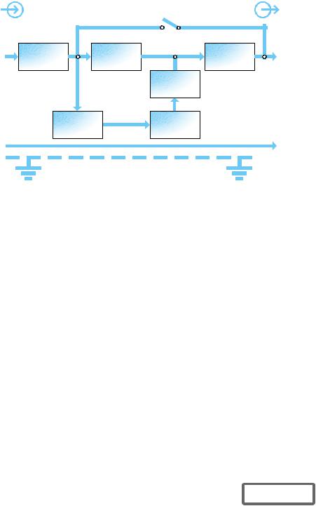
Input |
MAJOR COMPONENTS |
Output |
|
Dynamic |
|||
|
|
||
|
Bypass |
|
L1 |
TVSS & |
EMI/RFI |
|
|
Filters |
Rectifier |
/PFC |
DC to DC |
Converter |
Inverter |
L1 |
Battery |
Charger |
L2 |
G |
Battery |
L2
 G
G
Transient Voltage Surge Suppression and EMI/RFI Filters
These UPS components provide surge protection and filter both electromagnetic interference (EMI) and radio frequency interference (RFI). They minimize any surges or interference present in the utility line and keep the sensitive equipment protected.
Rectifier/Power Factor Correction (PFC) Circuit
In normal operation, the rectifier/power factor correction (PFC) circuit converts utility AC power to regulated DC power for use by the inverter while ensuring that the waveshape of the input current used by the UPS is near ideal. Extracting this sinewave input current achieves two objectives:
•The utility power is used as efficiently as possible by the UPS.
•The amount of distortion reflected on the utility is reduced.
This results in cleaner power being available to other devices in the building not being protected by the Liebert GXT2U.
Inverter
In normal operation, the inverter utilizes the DC output of the power factor correction circuit and inverts it into precise, regulated sinewave AC power. Upon a utility power failure, the inverter receives its required energy from the battery through the DC to DC converter. In both modes of operation, the UPS inverter is on-line and continuously generating clean, precise, regulated AC output power.
Battery Charger
The battery charger utilizes energy from the utility power and precisely regulates it to continuously “float charge” the batteries. The batteries are being charged whenever the Liebert GXT2U is plugged in, even when the UPS is not turned on.
5 |
DISCONTINUED |
|
PRODUCT |
||
|

DC-to-DC Converter
The DC-to-DC converter utilizes energy from the battery system and raises the DC voltage to the optimum operating voltage for the inverter. This allows the inverter to operate continuously at its optimum efficiency and voltage, thus increasing reliability.
Battery
The Liebert GXT2U utilizes valve-regulated, nonspillable lead acid batteries. To maintain battery design life, operate the UPS in an ambient temperature of 68°F to 77°F (20°C to 25°C). Optional external battery cabinets are available to extend battery run times.
Dynamic Bypass
The Liebert GXT2U provides an alternate path for utility power to the connected load in the unlikely event of a UPS malfunction. Should the UPS have an overload, overtemperature, or UPS failure condition, the UPS automatically transfers the connected load to bypass. Bypass operation is indicated by an audible alarm and illuminated amber Bypass LED (other LEDs may be illuminated to indicate the diagnosed problem). To manually transfer the connected load from the inverter to bypass, press the Standby button once.
NOTE
The bypass power path does NOT protect the connected equipment from disturbances on the utility supply.
6 |
DISCONTINUED |
|
PRODUCT |
||
|
Liebert GXT2U—Rear View |
|
|
|
|
Liebert |
DB-9 |
|
IntelliSlot® |
Communications Port |
|
Port |
|
|
Cooling |
|
|
Fans |
AC Input |
|
|
(L6-20) |
|
|
External |
|
Input Circuit |
|
Breaker |
|
Battery |
|
|
|
(20 amp) |
|
Connector |
|
|
|
|
|
Output |
|
|
Receptacle |
|
|
(L6-20R) |
|
|
Support |
|
|
Base |
|
|
|
|
Output |
|
|
Receptacles |
|
|
(L6-15R) |
|
7 |
DISCONTINUED |
|
PRODUCT |
|
|
|
INSTALLATION
Preparation
1.Visually inspect the UPS for freight damage. Report damage to the carrier and your local dealer or Liebert representative.
! CAUTION
The UPS is heavy (see Specifications section). Take proper precautions when lifting or moving it.
2.Decide where to place the Liebert GXT2U. Install the UPS indoors in a controlled environment, where it cannot be accidentally turned off. Place it in an area of unrestricted airflow around the unit, away from water, flammable liquids, gases, corrosives, and conductive contaminants. Maintain a minimum clearance of 4 inches (100mm) in the front and rear of the UPS. Maintain an ambient temperature range of 32°F to 104°F (0°C to 40°C).
NOTE
UPS operation in temperatures above 77°F (25°C) reduces battery life.
3.The Liebert GXT2U may be installed in either a tower configuration or in a rack, depending on available space and use considerations. Determine the type of installation and follow the appropriate instructions in either Tower UPS Installation or Rack-Mount UPS Conversion and Installation.
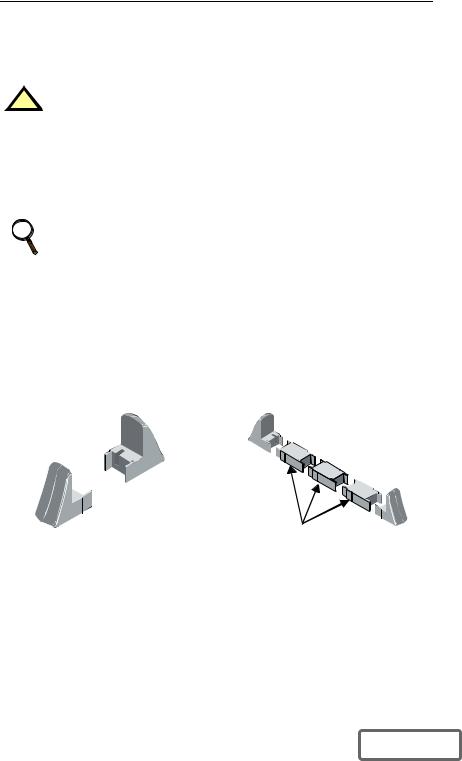
Tower UPS Installation
When using the Liebert GXT2U in a tower configuration, use the included support base (shown below, left) to stabilize the UPS.
If any battery cabinets are added, they will include spacers to accommodate the additional cabinets (shown below, right).
Support base |
Spacers added to support |
|
base to accommodate |
|
additional battery cabinets |
8 |
DISCONTINUED |
|
PRODUCT |
||
|
 Loading...