


 Loading...


 AC Power


 For Business-Critical Continuity™


 Liebert® Remote Monitoring Panel™


 User Manual
|
|
|
|
|
|
|
|
|
|
|
|
|
|
|
|
|
|
|
|
|
|
|
|
|
|
|
|
|
|
|
|
|
|
|
|
|
|
|
|
|
|
|
|
|
|
|
|
|
|
|
|
|
|
|
|
|
|
|
|
|
|
|
|
|
|
|
|
|
|
|
|
|
|
|
|
|
|
|
|
|
|
|
|
|
|
|
|
|
|
|
|
|
|
|
|
|
|
|
|
|
|
|
|
|
|
|
|
|
|
|
|
|
|
|
|
|
|
|
|
|
|
|
|
|
|
|
|
|
|
|
|
|
|
|
|
|
|
|
|
|
|
|
|
|
|
|
|
|
|
|
|
|
|
|
|
|
|
|
|
|
|
|
|
|
|
|
|
|
|
|
|
|
|
|
|
|
|
|
|
|
|
|
|
|
|
|
|
|
|
|
|
|
|
|
|
|
|
|
|
|
|
|
|
|
|
|
|
|
|
|
|
|
|
|
|
|
|
|
|
|
|
|
|
|
|
|
|
|
|
|
|
|
|
|
|
|
|
|
|
|
|
|
|
|
|
|
|
|
|
|
|
|
|
|
|
|
|
|
|
|
|
|
|
|
|
|
|
|
|
|
|
|
|
|
|
|
|
|
|
|
|
|
|
|
|
|
|
|
|
|
|
|
|
|
|
|
|
|
|
|
|
|
|
|
|
|
|
|
|
|
|
|
|
|
|
|
|
|
|
|
|
|
|
|
|
|
|
|
|
|
|
|
|
|
|
|
|
|
|
|
|
|
|
|
|
|
|
|
|
|
|
|
|
|
|
|
|
|
|
|
|
|
|
|
|
|
|
|
|
|
|
|
|
|
|
|
|
|
|
|
|
|
|
|
|
|
|
|
|
|
|
|
|
|
|
|
|
|
|
|
|
|
|
|
|
|
|
|
|
|
|
|
|
|
|
|
|
|
|
|
|
|
|
|
|
|
|
|
|
|
|
|
|
|
|
|
|
|
|
|
|
|
|
|
|
|
|
|
|
|
|
|
|
|
|
|
|
|
|
|
|
|
|
|
|
|
|
|
|
|
|
|
|
|
|
|
|
|
|
|
|
|
|
|
|
|
|
|
|
|
|
|
|
|
|
|
|
|
|
|
|
|
|
|
|
|
|
|
|
|
|
|
|
|
|
|
|
|
|
|
|
|
|
|
|
|
|
|
|
|
|
|
|
|
|
|
|
|
|
|
|
|
|
|
|
|
|
|
|
|
|
|
|
|
|
|
|
|
|
|
|
|
|
|
|
|
|
|
|
|
|
|
|
|
|
|
|
|
|
|
|
|
|
|
|
|
|
|
|
|
|
|
|
|
|
|
|
|
|
|
|
|
|
|
|
|
|
|
|
|
|
|
|
|
|
|
|
|
|
|
|
|
|
|
|
|
|
|
|
|
|
|
|
|
|
|
|
|
|
|
|
|
|
|
|
|
|
|
|
|
|
|
|
|
|
|
|
|
|
|
|
|
|
|
|
|
|
|
|
|
|
|
|
|
|
|
|
|
|
|
|
|
|
|
|
|
|
|
|
|
|
|
|
|
|
|
|
|
|
|
|
|
|
|
|
|
|
|
|
|
|
|
|
|
|
|
|
|
|
|
|
|
|
|
|
|
|
|
|
|
|
|
|
|
|
|
|
|
|
|
|
|
|
|
|
|
|
|
|
|
|
|
|
|
|
|
|
|
|
|
|
|
|
|
|
|
|
|
|
|
|
|
|
|
|
|
|
|
|
|
|
|
|
|
|
|
|
|
|
|
|
|
|
|
|
|
|
|
|
|
|
|
|
|
|
|
|
|
|
|
|
|
|
|
|
|
|
|
|
|
|
|
|
|
|
|
|
|
|
|
|
|
|
|
|
|
|
|
|
|
|
|
|
|
|
|
|
|
|
|
|
|
|
|
|
|
|
|
|
|
|
|
|
|
|
|
|
|
|
|
|
|
|
|
|
|
|
|
|
|
|
|
|
|
|
|
|
|
|
|
|
|
|
|
|
|
|
|
|
|
|
|
|
|
|
|
|
|
|
|
|
|
|
|
|
|
|
|
|
|
|
|
|
|
|
|
|
|
|
|
|
|
|
|
|
|
|
|
|
|
|
|
|
|
|
|
|
|
|
|
|
|
|
|
|
|
|
|
|
|
|
|
|
|
|
|
|
|
|
|
|
|
|
|
|
|
|
|
|
|
|
|
|
|
|
|
|
|
|
|
|
|
|
|
|
|
|
|
|
|
|
|
|
|
|
|
|
|
|
|
|
|
|
|
|
|
|
|
|
|
|
|
|
|
|
|
|
|
|
|
|
|
|
|
|
|
|
|
|
|
|
|
|
|
|
|
|
|
|
|
|
|
|
|
|
|
|
|
|
|
|
|
|
|
|
|
|
|
|
|
|
|
|
|
|
|
|
|
|
|
|
|
|
|
|
|
|
|
|
|
|
|
|
|
|
|
|
|
|
|
|
|
|
|
|
|
|
|
|
|
|
|
|
|
|
|
|
|
|
|
|
|
|
|
|
|
|
|
|
|
|
|
|
|
|
|
|
|
|
|
|
|
|
|
|
|
|
|
|
|
|
|
|
|
|
|
|
|
|
|
|
|
|
|
|
|
|
|
|
|
|
|
|
|
|
|
|
|
|
|
|
|
|
|
|
|
|
|
|
|
|
|
|
|
|
|
|
|
|
|
|
|
|
|
|
|
|
|
|
|
|
|
|
|
|
|
|
|
|
|
|
|
|
|
|
|
|
|
|
|
|
|
|
|
|
|
|
|
|
|
|
|
|
|
|
|
|
|
|
|
|
|
|
|
|
|
|
|
|
|
|
|
|
|
|
|
|
|
|
|
|
|
|
|
|
|
|
|
|
|
|
|
|
|
|
|
|
|
|
|
|
|
|
|
|
|
|
|
|
|
|
|
|
|
|
|
|
|
|
|
|
|
|
|
|
|
|
|
|
|
|
|
|
|
|
|
|
|
|
|
|
|
|
|
|
|
|
|
|
|
|
|
|
|
|
|
|
|
|
|
|
|
|
|
|
|
|
|
|
|
|
|
|
|
|
|
|
|
|
|
|
|
|
|
|
|
|
|
|
|
|
|
|
|
|
|
|
|
|
|
|
|
|
|
|
|
|
|
|
|
|
|
|
|
|
|
|
|
|
|
|
|
|
|
|
|
|
|
|
|
|
|
|
|
|
|
|
|
|
|
|
|
|
|
|
|
|
|
|
|
|
|
|
|
|
|
|
|
|
|
|
|
|
|
|
|
|
|
|
|
|
|
|
|
|
|
|
|
|
|
|
|
|
|
|
|
|
|
Liebert NX |
|
|
12- |
16 |
-2009 |
|
|
|
12:22:14 |
|
|
|
|
|
|
|
|
|
|
|
|
|
|
|
|
|
|
|
|
|
|
|
|
|
|
|
|
|
|
|
|
|
|
|
|
|
||||
|
|
|
|
|
|
|
|
|
|
|
|
|
|
|
|
|
|
|
|
|
|
|
|
|
|
|
|
|
|
|
|
|
|
|
|
|
|
|
|
|
|
|
|
|
|
|
|
|
|
|
|
|
|
|
|
|
|
|
|
|
|
|
|
|
|
|
|
|
|
|
|
|
|
|
|
|||||||||
|
|
|
|
|
|
|
|
|
|
|
|
|
|
|
|
|
|
|
|
|
|
|
|
|
|
|
|
|
|
|
|
|
|
|
|
|
|
|
|
|
|
|
|
|
|
|
|
|
|
|
|
|
|
|
|
|||||||||||||||||||||||||||||
|
|
|
|
|
|
|
|
|
|
|
|
|
|
|
|
|
|
|
|
|
|
|
|
|
|
|
|
|
|
|
|
|
|
081 kVA -3x3 |
|
Single |
|
|
Normal |
|
|
|
|
|
|
|
|
|
|
|
|
|
|
|
|
|
|
|
|
|
|
|
|
|
|
|
|
|
|
|
|
|
|
|
|
|||||||||
EMERSON™ |
|
Lie be rt N X |
Network Power |
|
|
|
EMERSON™ |
Remote Monitor Panel |
|
Network Power |
|
|
Liebert ® |
|
STATUS |
Press any key back to main menu |
SILENCE ON/OFF |
|
F1 |
F2 |
F3 |
F4 |
HELP |

TABLE OF CONTENTS
IMPORTANT SAFETY INSTRUCTIONS . . . . . . . . . . . . . . . . . . . . . . . . . . . . . . . . . . . . . . . . . . . . . . . .1 SAVE THESE INSTRUCTIONS . . . . . . . . . . . . . . . . . . . . . . . . . . . . . . . . . . . . . . . . . . . . . . . . .1 INFORMATION FOR THE PROTECTION OF THE ENVIRONMENT . . . . . . . . . . . . . . . . . . . .1 1.0 INTRODUCTION . . . . . . . . . . . . . . . . . . . . . . . . . . . . . . . . . . . . . . . . . . . . . . . . . . . . . . . . . .2 2.0 INSTALLATION . . . . . . . . . . . . . . . . . . . . . . . . . . . . . . . . . . . . . . . . . . . . . . . . . . . . . . . . . .4
2.1 Preliminary checks. . . . . . . . . . . . . . . . . . . . . . . . . . . . . . . . . . . . . . . . . . . . . . . . . . . . . . . . . . . 4 2.2 Location. . . . . . . . . . . . . . . . . . . . . . . . . . . . . . . . . . . . . . . . . . . . . . . . . . . . . . . . . . . . . . . . . . . . 4 2.3 Power Supply . . . . . . . . . . . . . . . . . . . . . . . . . . . . . . . . . . . . . . . . . . . . . . . . . . . . . . . . . . . . . . . 4 2.4 Cable Specifications . . . . . . . . . . . . . . . . . . . . . . . . . . . . . . . . . . . . . . . . . . . . . . . . . . . . . . . . . . 4 2.5 Mounting the RMP on Drywall . . . . . . . . . . . . . . . . . . . . . . . . . . . . . . . . . . . . . . . . . . . . . . . . . 5 2.6 Electrical connections. . . . . . . . . . . . . . . . . . . . . . . . . . . . . . . . . . . . . . . . . . . . . . . . . . . . . . . . . 6
3.0 OPERATION . . . . . . . . . . . . . . . . . . . . . . . . . . . . . . . . . . . . . . . . . . . . . . . . . . . . . . . . . . . .8
3.1 Startup and Reset. . . . . . . . . . . . . . . . . . . . . . . . . . . . . . . . . . . . . . . . . . . . . . . . . . . . . . . . . . . . 8 3.2 LED Mimic Power Flow . . . . . . . . . . . . . . . . . . . . . . . . . . . . . . . . . . . . . . . . . . . . . . . . . . . . . . 11 3.3 Audible Alarms—Buzzer . . . . . . . . . . . . . . . . . . . . . . . . . . . . . . . . . . . . . . . . . . . . . . . . . . . . . 11 3.4 Direct Access Push Buttons—Keys . . . . . . . . . . . . . . . . . . . . . . . . . . . . . . . . . . . . . . . . . . . . . 12 3.5 LCD Monitor and Menu Keys . . . . . . . . . . . . . . . . . . . . . . . . . . . . . . . . . . . . . . . . . . . . . . . . . 12 3.6 Detailed Description of Menu Items . . . . . . . . . . . . . . . . . . . . . . . . . . . . . . . . . . . . . . . . . . . . 14 3.7 Status and Event Messages . . . . . . . . . . . . . . . . . . . . . . . . . . . . . . . . . . . . . . . . . . . . . . . . . . . 16 3.8 Prompt (Popup) Windows . . . . . . . . . . . . . . . . . . . . . . . . . . . . . . . . . . . . . . . . . . . . . . . . . . . . 20 3.9 Dynamic Energy Flow Chart and UPS Help Screen . . . . . . . . . . . . . . . . . . . . . . . . . . . . . . . 20 3.10 Default screen saver. . . . . . . . . . . . . . . . . . . . . . . . . . . . . . . . . . . . . . . . . . . . . . . . . . . . . . . . . 21
4.0 TECHNICAL SPECIFICATIONS . . . . . . . . . . . . . . . . . . . . . . . . . . . . . . . . . . . . . . . . . . . . . . .22
4.1 Agency and Certifications . . . . . . . . . . . . . . . . . . . . . . . . . . . . . . . . . . . . . . . . . . . . . . . . . . . . 23
i

FIGURES
Figure 1 Remote Monitoring Panel components and functions. . . . . . . . . . . . . . . . . . . . . . . . . . . . . . . . . . . . 2 Figure 2 Remote Monitoring Panel layout constraints . . . . . . . . . . . . . . . . . . . . . . . . . . . . . . . . . . . . . . . . . . 3 Figure 3 RMP electrical input plug. . . . . . . . . . . . . . . . . . . . . . . . . . . . . . . . . . . . . . . . . . . . . . . . . . . . . . . . . . 4 Figure 4 Communication cable connection. . . . . . . . . . . . . . . . . . . . . . . . . . . . . . . . . . . . . . . . . . . . . . . . . . . . 5 Figure 5 Mounting hole dimensions . . . . . . . . . . . . . . . . . . . . . . . . . . . . . . . . . . . . . . . . . . . . . . . . . . . . . . . . . 5 Figure 6 Power and communication cable routing. . . . . . . . . . . . . . . . . . . . . . . . . . . . . . . . . . . . . . . . . . . . . . 6 Figure 7 RS-485 cable connection to Liebert NX . . . . . . . . . . . . . . . . . . . . . . . . . . . . . . . . . . . . . . . . . . . . . . . 7 Figure 8 Opening screen . . . . . . . . . . . . . . . . . . . . . . . . . . . . . . . . . . . . . . . . . . . . . . . . . . . . . . . . . . . . . . . . . . 8 Figure 9 Data loading progress screen . . . . . . . . . . . . . . . . . . . . . . . . . . . . . . . . . . . . . . . . . . . . . . . . . . . . . . . 8 Figure 10 UPS and RMP firmware are compatible screen . . . . . . . . . . . . . . . . . . . . . . . . . . . . . . . . . . . . . . . . 9 Figure 11 Silence On/Off screens . . . . . . . . . . . . . . . . . . . . . . . . . . . . . . . . . . . . . . . . . . . . . . . . . . . . . . . . . . . . 9 Figure 12 Communication with UPS failed . . . . . . . . . . . . . . . . . . . . . . . . . . . . . . . . . . . . . . . . . . . . . . . . . . . 10 Figure 13 Firmware not compatible with UPS screen. . . . . . . . . . . . . . . . . . . . . . . . . . . . . . . . . . . . . . . . . . . 10 Figure 14 Graphic LCD monitor windows and keypad . . . . . . . . . . . . . . . . . . . . . . . . . . . . . . . . . . . . . . . . . . 12 Figure 15 Menu tree . . . . . . . . . . . . . . . . . . . . . . . . . . . . . . . . . . . . . . . . . . . . . . . . . . . . . . . . . . . . . . . . . . . . . 13 Figure 16 Help screen . . . . . . . . . . . . . . . . . . . . . . . . . . . . . . . . . . . . . . . . . . . . . . . . . . . . . . . . . . . . . . . . . . . . 21 Figure 17 Default screen . . . . . . . . . . . . . . . . . . . . . . . . . . . . . . . . . . . . . . . . . . . . . . . . . . . . . . . . . . . . . . . . . . 21
TABLES
Table 1 RMP component location in Figure 1 . . . . . . . . . . . . . . . . . . . . . . . . . . . . . . . . . . . . . . . . . . . . . . . . 3 Table 2 Communication cable specifications . . . . . . . . . . . . . . . . . . . . . . . . . . . . . . . . . . . . . . . . . . . . . . . . . 4 Table 3 Rectifier indicator . . . . . . . . . . . . . . . . . . . . . . . . . . . . . . . . . . . . . . . . . . . . . . . . . . . . . . . . . . . . . . . 11 Table 4 Battery indicator . . . . . . . . . . . . . . . . . . . . . . . . . . . . . . . . . . . . . . . . . . . . . . . . . . . . . . . . . . . . . . . . 11 Table 5 Bypass indicator . . . . . . . . . . . . . . . . . . . . . . . . . . . . . . . . . . . . . . . . . . . . . . . . . . . . . . . . . . . . . . . . 11 Table 6 Inverter indicator . . . . . . . . . . . . . . . . . . . . . . . . . . . . . . . . . . . . . . . . . . . . . . . . . . . . . . . . . . . . . . . 11 Table 7 Load indicator . . . . . . . . . . . . . . . . . . . . . . . . . . . . . . . . . . . . . . . . . . . . . . . . . . . . . . . . . . . . . . . . . . 11 Table 8 Status (Alarm) indicator. . . . . . . . . . . . . . . . . . . . . . . . . . . . . . . . . . . . . . . . . . . . . . . . . . . . . . . . . . 11 Table 9 Audible alarm key. . . . . . . . . . . . . . . . . . . . . . . . . . . . . . . . . . . . . . . . . . . . . . . . . . . . . . . . . . . . . . . 11 Table 10 Menu key Icons and their meaning . . . . . . . . . . . . . . . . . . . . . . . . . . . . . . . . . . . . . . . . . . . . . . . . . 12 Table 11 UPS system window . . . . . . . . . . . . . . . . . . . . . . . . . . . . . . . . . . . . . . . . . . . . . . . . . . . . . . . . . . . . . 14 Table 12 Descriptions of RMP menus and data window items . . . . . . . . . . . . . . . . . . . . . . . . . . . . . . . . . . . 14 Table 13 RMP messages. . . . . . . . . . . . . . . . . . . . . . . . . . . . . . . . . . . . . . . . . . . . . . . . . . . . . . . . . . . . . . . . . . 16 Table 14 Prompt windows, meanings controlled at UPS only . . . . . . . . . . . . . . . . . . . . . . . . . . . . . . . . . . . . 20 Table 15 Prompt windows, meanings controlled at RMP . . . . . . . . . . . . . . . . . . . . . . . . . . . . . . . . . . . . . . . 20 Table 16 Mechanical specifications . . . . . . . . . . . . . . . . . . . . . . . . . . . . . . . . . . . . . . . . . . . . . . . . . . . . . . . . . 22 Table 17 Environmental specifications . . . . . . . . . . . . . . . . . . . . . . . . . . . . . . . . . . . . . . . . . . . . . . . . . . . . . . 22 Table 18 Electrical specifications . . . . . . . . . . . . . . . . . . . . . . . . . . . . . . . . . . . . . . . . . . . . . . . . . . . . . . . . . . 22 Table 19 Cable specifications. . . . . . . . . . . . . . . . . . . . . . . . . . . . . . . . . . . . . . . . . . . . . . . . . . . . . . . . . . . . . . 22 Table 20 Electromagnetic interference (EMI)—emission limits . . . . . . . . . . . . . . . . . . . . . . . . . . . . . . . . . . 23 Table 21 Electromagnetic susceptibility (EMS)—immunity levels . . . . . . . . . . . . . . . . . . . . . . . . . . . . . . . . 23
ii

IMPORTANT SAFETY INSTRUCTIONS
SAVE THESE INSTRUCTIONS
This manual contains important safety and operating instructions concerning the installation and operation of the Liebert NX Remote Monitoring Panel (RMP). Read all safety, installation and operating instructions before beginning installation. Adhere to all warnings on the unit and in this manual. Follow all operating and user instructions.
The Liebert NX Remote Monitoring Panel must be commissioned and serviced by an engineer approved by Liebert. Failure to do so may result in personnel safety risk, equipment malfunction and invalidation of warranty.
The Remote Monitoring Panel is designed and intended for commercial and industrial use. It is not recommended for use in life-support applications.
ELECTROMAGNETIC COMPATIBILITY—This is a low-emission, Class A product. Operating this device in a residential area is likely to cause harmful interference that users must correct at their own expense. Pursuant to FCC regulations, operation is subject to the following two conditions:
1.This device may not cause harmful interference; and
2.This device must accept any interference received, including interference that may cause undesired operation.
Conformity and Standards
This equipment complies with CE directives 73/23 & 93/68 (LV Safety) and 89/336 (EMC), with Australia and New Zealand EMC Framework (C-Tick) and with the following product standards for Uninterruptible Power System (UPS).
•EN / IEC / AS 62040-1-1-General and safety requirements for use in operator access area
•EN / IEC / AS 62040-2-EMC requirements; Class A compliant
•EN / IEC / AS 62040-3-Performance requirements and test methods
This equipment complies with UL 60950-1:2003, First Edition CSA C22.2 No. 60950-1-03 1st Ed.
April 1, 2003.
For details, see 4.0 - Technical Specifications.
Continued compliance requires installation in accordance with these instructions and the use of manufacturer approved accessories only.
General
The unit must be grounded in accordance with applicable current local electrical regulations.
As with other types of power equipment, dangerous voltages are present within the RMP enclosure. The risk of contact with these voltages is minimized as the live component parts are housed behind a hinged, lockable door. No risk exists to any personnel when operating the equipment in the normal manner, following the recommended operating procedures.
All equipment maintenance and servicing procedures involve internal access and should be carried out only by trained personnel.
User-Serviceable Parts
There are no user-serviceable parts behind covers requiring a tool for removal. All equipment maintenance and servicing procedures involving internal access requires the use of a tool and should be carried out only by trained personnel.
INFORMATION FOR THE PROTECTION OF THE ENVIRONMENT
Unit Servicing
This unit makes use of components dangerous for the environment, including electronic cards and other electronic components. Any of these components that are removed from the unit must be taken to specialized collection and disposal centers.
Unit Dismantling
If this unit must be dismantled, this operation must be carried out only by properly trained and qualified specialized personnel. The unit must be taken to a center that specializes in collection and disposal of dangerous substances.
1
Introduction
1.0INTRODUCTION
The Liebert NX Remote Monitoring Panel (RMP) is designed as a remote user interface to monitor Liebert NX Uninterruptible Power Systems. The RMP monochrome liquid crystal display measures 122 x 92mm (4.8 x 3.6 inches). It reports the same data and status and alarm messages that are shown by the LCD on the UPS’s door. The RMP does not offer control of the UPS.
The RMP should be installed in a room where it is readily and easily observed by personnel, such as facility and maintenance staff. This type location enhances the unit’s capacity to provide notice if a status change or alarm requires an electrician or a UPS technician's intervention.
The RMP can monitor only one Liebert NX UPS. If there are multiple Liebert NX UPSs, an RMP will need to be installed for each unit. For parallel systems, the system load information may be viewed via the system screen from any RMP that is connected to a UPS in that system (see 3.6 - Detailed Description of Menu Items.)
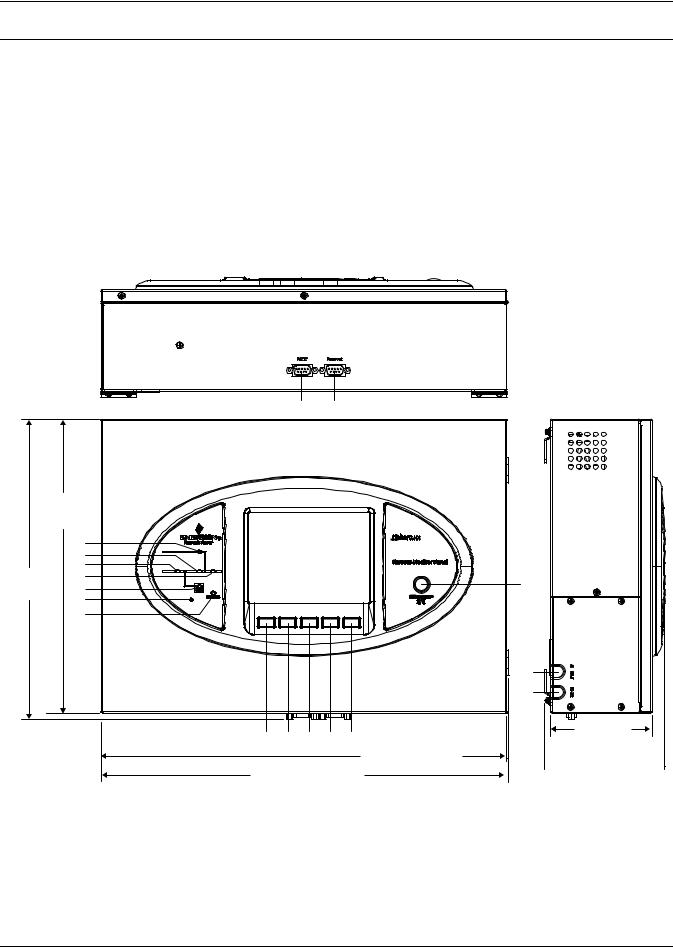
Figure 1 Remote Monitoring Panel components and functions
|
|
|
|
14 |
15 |
|
11-13/32" |
|
|
|
|
|
|
(290mm) |
|
|
|
|
|
|
|
1 |
|
|
|
|
|
|
2 |
|
|
|
|
|
|
3 |
|
|
|
|
|
11-21/32" |
4 |
|
|
|
|
13 |
(296mm) |
5 |
|
|
|
|
|
|
6 |
F1 |
F2 |
F3 |
F4 |
HELP |
|
7 |
|||||
|
|
|
|
|
|
|
|
|
|
|
|
|
16 |
|
|
|
|
|
|
17 |
|
|
8 |
9 |
10 |
11 |
12 |
|
|
|
|
|
|
15-3/4" (400mm) |
15-53/64" (402mm)
4-15/16" (100mm)
 4-41/64"
  (118mm)
2
Introduction
Table 1 |
RMP component location in Figure 1 |
|||
|
|
|
|
|
1 |
Bypass Input |
10 |
F3 Function Key |
|
|
|
|
|
|
2 |
Inverter—DC to AC |
11 |
F4 Function Key |
|
3 |
Rectifier—Input AC to DC |
12 |
Help Key |
|
|
|
|
|
|
4 |
Load—AC Output |
13 |
Silence On/Off Audible—Alarm Mute |
|
|
|
|
|
|
5 |
Battery—DC Backup |
14 |
RS-232—for firmware update |
|
6 |
Audible Alarm—Buzzer |
15 |
RS-232—Reserved, not used |
|
|
|
|
|
|
7 |
UPS Status and Alarm indicator |
16 |
AC power input cable entry |
|
|
|
|
|
|
8 |
F1 Function Key |
17 |
RS-485 communication cable entry |
|
9 |
F2 Function Key |
|
|
|
|
|
|
|
|
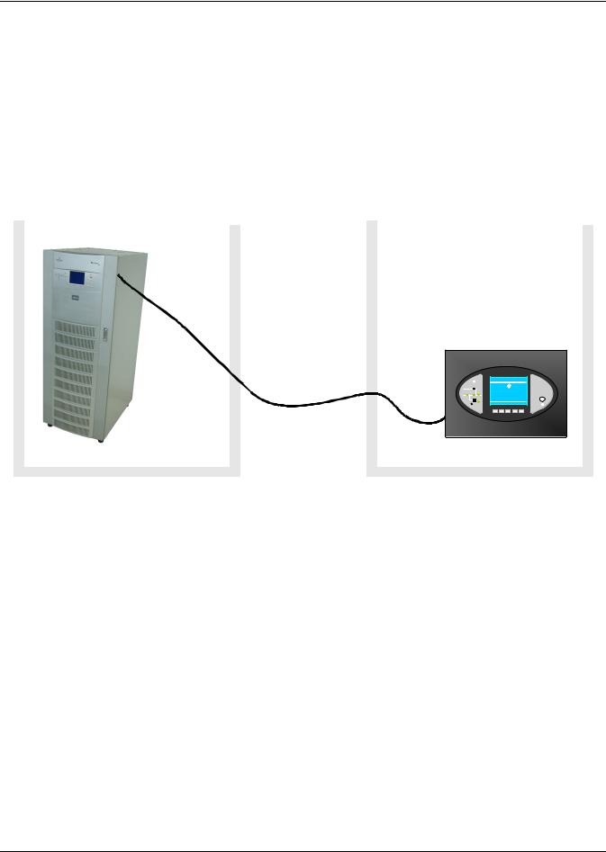
Figure 2 Remote Monitoring Panel layout constraints
|
|
|
UPS Room |
|
Maintenance or Control Room |
Liebert NX |
12-16-2009 |
12:22:14 |
081 kVA -3x3 |
Single |
Normal |
EMERSON™ |
L ie b e rt |
Network Power |
|
EMERSON™ |
Remote Monitor Panel |
Network Power |
|
Liebert ® |
|
Press any key back to main menu |
|
F1 F2 F3 F4 HELP |
|
Communication
Cable; Maximum Length Liebert NX 100m (328ft.) (field-supplied)
3
Installation
2.0INSTALLATION
2.1Preliminary checks
Before beginning to install the RMP, verify that the equipment has reached site in its own packaging and in good general condition. Please notify immediately the shipper, Emerson Network Power and your local Liebert representative of any damage.
These items should be included in the package:
•RMP box with LCD screen
•4 mounting screws
•4 plastic wall anchors (6mm-by-26mm)
•2 Phoenix connectors for connection with the UPS.
•User manual
2.2Location
The RMP is designed for indoor use and should be installed in an environment with clean air and adequate ventilation to keep the temperature within the specified operating range (see Table 17).
If the RMP is to be installed on a wall or other vertical surface, ensure that the surface can bear the weight (see Table 16) and there is no water leakage.
2.3Power Supply
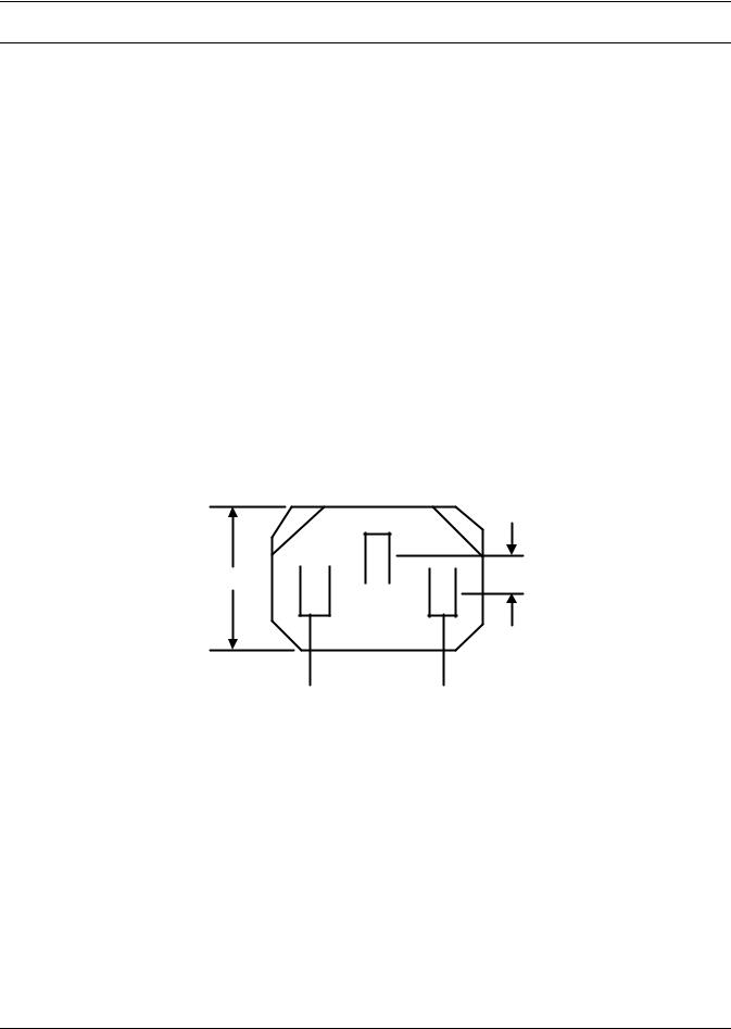
The RMP requires a 120V/230V AC input (for detailed electrical specifications, see Table 18).
Figure 3 RMP electrical input plug
15.6mm 

 4mm
4mm
 14mm
14mm 
2.4Cable Specifications
Connect the RMP to the Liebert NX with a field-supplied communication cable meeting the specifications in Table 2.
Table 2 |
Communication cable specifications |
||
|
|
|
|
No |
|
Item |
Specification |
|
|
|
|
1 |
Connector type |
Both terminals are all 4-pin Phoenix terminal (supplied with RMP). |
|
|
|
|
|
2 |
Cable Length |
<100m |
|
|
|
|
|
3 |
Cable type |
a shielded and twisted pair of 0.5 to 1 mm2 (16-20AWG) wires |
|
4 |
Connection mode |
See Figure 4 |
|
|
|
|
|
4
Installation
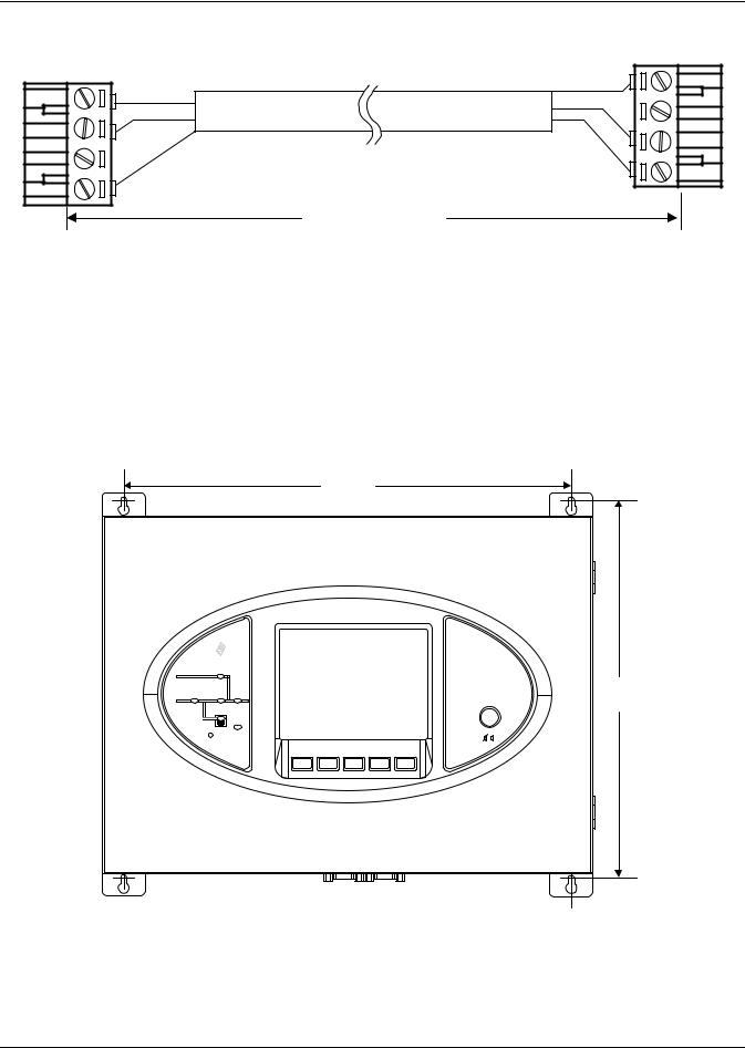
Figure 4 Communication cable connection
|
RMP_X1_J1 |
4 |
485- |
|
|
3 |
485+ |
|
|
2 |
Shield |
|
|
1 |
|
Up to 328ft. (100m)
|
UPS_U2_J24 |
|
Shield |
1 |
|
485+ |
2 |
|
485- |
||
3 |
||
|
||
|
4 |
2.5Mounting the RMP on Drywall
To hang the RMP on drywall or similar surface:
1.Drill four holes (6mm-by-26mm) in the wall, spacing them as shown in Figure 5.
2.Insert the four factory-supplied, plastic anchors into the holes.
3.Insert one screw into each anchor and tighten firmly.
4.Remove the four hooks from the RMP, reverse them, then reattach them to the RMP.
5.Hang the RMP on the wall by slipping the hooks over the heads of the screws and lowering the RMP slowly until the screws are seated in the slotted portion of the hooks.
Figure 5 Mounting hole dimensions
14-3/16" (365mm)
EmersonTM |
Liebert NX |
|
Network Power |
|
|
|
Remote Monitor Panel |
12" |
|
|
(306mm) |
STATUS |
SILENCE ON/OFF |
|
F1 F2 F3 F4 HELP
5
Loading...