


 Loading...


 Monitoring


 For Business-Critical Continuity™


 Liebert® IntelliSlot® Web Cards


 Installation Manual – Liebert IntelliSlot Web Card, Liebert IntelliSlot Web Card-LB,


 Liebert IntelliSlot Web Card-LBDS, Liebert IntelliSlot Web/485 Card-ADPT

TABLE OF CONTENTS
IMPORTANT SAFETY INSTRUCTIONS . . . . . . . . . . . . . . . . . . . . . . . . . . . . . . . . . . . . . . . . . . . . . . . .1
1.0 INTRODUCTION . . . . . . . . . . . . . . . . . . . . . . . . . . . . . . . . . . . . . . . . . . . . . . . . . . . . . . . . . .2
1.1 Compatibility With Liebert Equipment . . . . . . . . . . . . . . . . . . . . . . . . . . . . . . . . . . . . . . . . . . 2 1.2 Web Support . . . . . . . . . . . . . . . . . . . . . . . . . . . . . . . . . . . . . . . . . . . . . . . . . . . . . . . . . . . . . . . . 3 1.3 Password Protection. . . . . . . . . . . . . . . . . . . . . . . . . . . . . . . . . . . . . . . . . . . . . . . . . . . . . . . . . . 3
1.4 SNMP Support . . . . . . . . . . . . . . . . . . . . . . . . . . . . . . . . . . . . . . . . . . . . . . . . . . . . . . . . . . . . . . 3 1.5 Liebert Nform™ Support . . . . . . . . . . . . . . . . . . . . . . . . . . . . . . . . . . . . . . . . . . . . . . . . . . . . . . 3 1.6 Liebert MultiLink™ Support . . . . . . . . . . . . . . . . . . . . . . . . . . . . . . . . . . . . . . . . . . . . . . . . . . . 3
1.7 Liebert SiteScan® Web With Modbus Support - IS-WEB485ADPT only . . . . . . . . . . . . . . . . 3
2.0 INSTALLATION . . . . . . . . . . . . . . . . . . . . . . . . . . . . . . . . . . . . . . . . . . . . . . . . . . . . . . . . . .4
2.1 Install a Liebert IntelliSlot Web Card—Non-Adapter Version . . . . . . . . . . . . . . . . . . . . . . . . 4 2.2 Install a Liebert IntelliSlot Web/485 Card With Adapter . . . . . . . . . . . . . . . . . . . . . . . . . . . . 5
3.0 CONFIGURATION OVERVIEW . . . . . . . . . . . . . . . . . . . . . . . . . . . . . . . . . . . . . . . . . . . . . . . .6
3.1 Guide to Configuration. . . . . . . . . . . . . . . . . . . . . . . . . . . . . . . . . . . . . . . . . . . . . . . . . . . . . . . . 6 3.2 Open the Terminal Emulation Interface - Serial Connection . . . . . . . . . . . . . . . . . . . . . . . . . 7 3.3 Open the Terminal Emulation Interface - TCP/IP Connection . . . . . . . . . . . . . . . . . . . . . . . . 8 3.4 Open the Telnet Interface . . . . . . . . . . . . . . . . . . . . . . . . . . . . . . . . . . . . . . . . . . . . . . . . . . . . . 9 3.5 Open the Web Interface . . . . . . . . . . . . . . . . . . . . . . . . . . . . . . . . . . . . . . . . . . . . . . . . . . . . . . 10 3.6 Saving Changes and Reinitializing the Web Card . . . . . . . . . . . . . . . . . . . . . . . . . . . . . . . . . 10
4.0 SYSTEM INFORMATION . . . . . . . . . . . . . . . . . . . . . . . . . . . . . . . . . . . . . . . . . . . . . . . . . . . 11
5.0 NETWORK SETTINGS . . . . . . . . . . . . . . . . . . . . . . . . . . . . . . . . . . . . . . . . . . . . . . . . . . . .12
5.1 Boot/IP Settings . . . . . . . . . . . . . . . . . . . . . . . . . . . . . . . . . . . . . . . . . . . . . . . . . . . . . . . . . . . . 13 5.2 Domain Name Server (DNS) Settings. . . . . . . . . . . . . . . . . . . . . . . . . . . . . . . . . . . . . . . . . . . 14 5.3 Management Protocol. . . . . . . . . . . . . . . . . . . . . . . . . . . . . . . . . . . . . . . . . . . . . . . . . . . . . . . . 15 5.4 Web Server . . . . . . . . . . . . . . . . . . . . . . . . . . . . . . . . . . . . . . . . . . . . . . . . . . . . . . . . . . . . . . . . 19 5.5 Telnet Server . . . . . . . . . . . . . . . . . . . . . . . . . . . . . . . . . . . . . . . . . . . . . . . . . . . . . . . . . . . . . . 24 5.6 Time (SNTP) Menu. . . . . . . . . . . . . . . . . . . . . . . . . . . . . . . . . . . . . . . . . . . . . . . . . . . . . . . . . . 24 5.7 Change Username / Password . . . . . . . . . . . . . . . . . . . . . . . . . . . . . . . . . . . . . . . . . . . . . . . . . 26 5.8 Reset Authentication to Factory Defaults. . . . . . . . . . . . . . . . . . . . . . . . . . . . . . . . . . . . . . . . 27
6.0 MESSAGING . . . . . . . . . . . . . . . . . . . . . . . . . . . . . . . . . . . . . . . . . . . . . . . . . . . . . . . . . . .28
6.1 E-Mail Configuration . . . . . . . . . . . . . . . . . . . . . . . . . . . . . . . . . . . . . . . . . . . . . . . . . . . . . . . . 29 6.2 SMS Configuration. . . . . . . . . . . . . . . . . . . . . . . . . . . . . . . . . . . . . . . . . . . . . . . . . . . . . . . . . . 30 6.3 Customize Messages. . . . . . . . . . . . . . . . . . . . . . . . . . . . . . . . . . . . . . . . . . . . . . . . . . . . . . . . . 32
7.0 FACTORY SETTINGS . . . . . . . . . . . . . . . . . . . . . . . . . . . . . . . . . . . . . . . . . . . . . . . . . . . . .34
7.1 Reset to Factory Defaults. . . . . . . . . . . . . . . . . . . . . . . . . . . . . . . . . . . . . . . . . . . . . . . . . . . . . 34 7.2 Liebert DS - Local Node Settings for Multiple Cards. . . . . . . . . . . . . . . . . . . . . . . . . . . . . . . 35
8.0 MONITOR AND CONTROL FUNCTIONS - WEB ONLY . . . . . . . . . . . . . . . . . . . . . . . . . . . . . .36
8.1 Monitoring Liebert Equipment . . . . . . . . . . . . . . . . . . . . . . . . . . . . . . . . . . . . . . . . . . . . . . . . 36 8.2 Controlling Liebert Equipment . . . . . . . . . . . . . . . . . . . . . . . . . . . . . . . . . . . . . . . . . . . . . . . . 37 8.3 Event Log . . . . . . . . . . . . . . . . . . . . . . . . . . . . . . . . . . . . . . . . . . . . . . . . . . . . . . . . . . . . . . . . . 38
i

9.0 SUPPORT INFORMATION . . . . . . . . . . . . . . . . . . . . . . . . . . . . . . . . . . . . . . . . . . . . . . . . . .39
9.1 View Web Card Information . . . . . . . . . . . . . . . . . . . . . . . . . . . . . . . . . . . . . . . . . . . . . . . . . . 39
9.2 Events and Parameters . . . . . . . . . . . . . . . . . . . . . . . . . . . . . . . . . . . . . . . . . . . . . . . . . . . . . . 40
APPENDIX A - FIRMWARE UPDATES. . . . . . . . . . . . . . . . . . . . . . . . . . . . . . . . . . . . . . . . . . . . . . A1
FIGURES
Figure A1 Null connection . . . . . . . . . . . . . . . . . . . . . . . . . . . . . . . . . . . . . . . . . . . . . . . . . . . . . . . . . . . . . . . . A10
TABLES
Table 1 Liebert IntelliSlot card communication protocols . . . . . . . . . . . . . . . . . . . . . . . . . . . . . . . . . . . . . . . 2 Table 2 Communication settings . . . . . . . . . . . . . . . . . . . . . . . . . . . . . . . . . . . . . . . . . . . . . . . . . . . . . . . . . . . 4 Table 3 Communication settings . . . . . . . . . . . . . . . . . . . . . . . . . . . . . . . . . . . . . . . . . . . . . . . . . . . . . . . . . . . 5 Table 4 Configuration interfaces . . . . . . . . . . . . . . . . . . . . . . . . . . . . . . . . . . . . . . . . . . . . . . . . . . . . . . . . . . . 6 Table 5 Guide to configuration details . . . . . . . . . . . . . . . . . . . . . . . . . . . . . . . . . . . . . . . . . . . . . . . . . . . . . . 6 Table 6 Communication settings . . . . . . . . . . . . . . . . . . . . . . . . . . . . . . . . . . . . . . . . . . . . . . . . . . . . . . . . . . . 7 Table 7 System information identifiers. . . . . . . . . . . . . . . . . . . . . . . . . . . . . . . . . . . . . . . . . . . . . . . . . . . . . 11 Table 8 Network Settings menu guide . . . . . . . . . . . . . . . . . . . . . . . . . . . . . . . . . . . . . . . . . . . . . . . . . . . . . 12 Table 9 Boot/IP settings range . . . . . . . . . . . . . . . . . . . . . . . . . . . . . . . . . . . . . . . . . . . . . . . . . . . . . . . . . . . 13 Table 10 Domain Name Server settings . . . . . . . . . . . . . . . . . . . . . . . . . . . . . . . . . . . . . . . . . . . . . . . . . . . . . 14 Table 11 Management protocol ranges . . . . . . . . . . . . . . . . . . . . . . . . . . . . . . . . . . . . . . . . . . . . . . . . . . . . . . 15 Table 12 SNMP communications menu . . . . . . . . . . . . . . . . . . . . . . . . . . . . . . . . . . . . . . . . . . . . . . . . . . . . . 17 Table 13 Web server settings. . . . . . . . . . . . . . . . . . . . . . . . . . . . . . . . . . . . . . . . . . . . . . . . . . . . . . . . . . . . . . 19 Table 14 Time Server parameters . . . . . . . . . . . . . . . . . . . . . . . . . . . . . . . . . . . . . . . . . . . . . . . . . . . . . . . . . . 25 Table 15 Factory default passwords . . . . . . . . . . . . . . . . . . . . . . . . . . . . . . . . . . . . . . . . . . . . . . . . . . . . . . . . 26 Table 16 Username and password guidelines . . . . . . . . . . . . . . . . . . . . . . . . . . . . . . . . . . . . . . . . . . . . . . . . 26 Table 17 Factory default passwords . . . . . . . . . . . . . . . . . . . . . . . . . . . . . . . . . . . . . . . . . . . . . . . . . . . . . . . . 27 Table 18 Messaging menu guide . . . . . . . . . . . . . . . . . . . . . . . . . . . . . . . . . . . . . . . . . . . . . . . . . . . . . . . . . . . 28 Table 19 E-mail configuration guide . . . . . . . . . . . . . . . . . . . . . . . . . . . . . . . . . . . . . . . . . . . . . . . . . . . . . . . . 29 Table 20 SMS configuration guide . . . . . . . . . . . . . . . . . . . . . . . . . . . . . . . . . . . . . . . . . . . . . . . . . . . . . . . . . 31 Table 21 E-mail and SMS message guidelines . . . . . . . . . . . . . . . . . . . . . . . . . . . . . . . . . . . . . . . . . . . . . . . . 32 Table 22 Factory default MAC addresses . . . . . . . . . . . . . . . . . . . . . . . . . . . . . . . . . . . . . . . . . . . . . . . . . . . . 35 Table 23 Control operations parameters—functions vary by Liebert unit . . . . . . . . . . . . . . . . . . . . . . . . . . 37 Table A1 Overview of the upgrade process . . . . . . . . . . . . . . . . . . . . . . . . . . . . . . . . . . . . . . . . . . . . . . . . . . . A1 Table A2 Estimated Time for downloads. . . . . . . . . . . . . . . . . . . . . . . . . . . . . . . . . . . . . . . . . . . . . . . . . . . . . A1 Table A3 Communication settings . . . . . . . . . . . . . . . . . . . . . . . . . . . . . . . . . . . . . . . . . . . . . . . . . . . . . . . . . . A2 Table A4 Firmware update settings - TFTP . . . . . . . . . . . . . . . . . . . . . . . . . . . . . . . . . . . . . . . . . . . . . . . . . . A6 Table A5 Firmware update settings - Web . . . . . . . . . . . . . . . . . . . . . . . . . . . . . . . . . . . . . . . . . . . . . . . . . . . A8
ii

IMPORTANT SAFETY INSTRUCTIONS
SAVE THESE INSTRUCTIONS
! WARNING
Only a qualified service professional should install these products. Liebert recommends having an Emerson Network Power Liebert Services representative perform the installation in large UPSs. Contact Liebert Services at 1-800-LIEBERT (1-800-543-2378).
! WARNING
Risk of electric shock. Can cause equipment damage, injury or death.
Service and maintenance work must be performed only by properly trained and qualified personnel and in accordance with applicable regulations and manufacturers’ specifications.
Opening or removing the covers to any equipment may expose personnel to lethal voltages within the unit even when it is apparently not operating and the input wiring is disconnected from the electrical source.
Check the circuits with a voltmeter before beginning installation.
1
Introduction
1.0INTRODUCTION
The Liebert® IntelliSlot® Web Card family delivers enhanced communications and control to Liebert AC Power and Precision Cooling systems.
Liebert IntelliSlot Web cards bring SNMP, Telnet and Web-management capability to many models of Liebert power and cooling equipment. The cards employ an Ethernet network to monitor and manage a wide range of operating parameters, alarms and notifications.
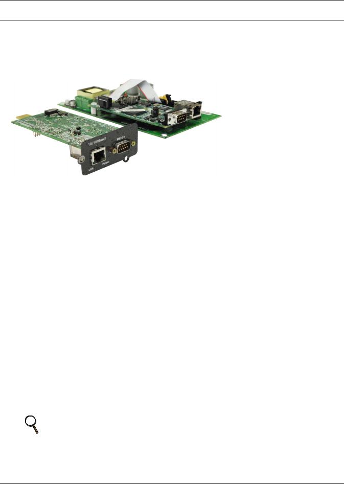
Liebert IntelliSlot Web/485 Card With Adapter
IS-WEB485ADPT
Liebert IntelliSlot Web card
IS-WEBCARD, IS-WEBLB and IS-WEBLBDS
1.1Compatibility With Liebert Equipment
The Liebert IntelliSlot Web Card family, formerly the OpenComms line, includes:
•Liebert IntelliSlot Web Card
Compatible with these Liebert UPS models: Liebert PowerSure PSI™, Liebert GXT™, Liebert GXT™ 6kVA & Liebert GXT™ 10kVA, Liebert GXT2U™ and Liebert Nfinity®
•Liebert IntelliSlot Web Card-LB
Compatible with the Liebert NX™ and Liebert Hinet™ UPS models
•Liebert IntelliSlot Web Card-LBDS
Compatible with the Liebert DS™ Precision Cooling unit and the Liebert XDF™
•Liebert IntelliSlot Web/485 Card-ADPT
Compatible with Liebert AC Power and Precision Cooling systems not equipped with a Liebert IntelliSlot port
Table 1 |
Liebert IntelliSlot card communication protocols |
|
|
|
|
|
||||
|
|
|
|
|
|
|
|
|
|
|
|
|
|
|
|
Communication Protocol |
|
|
|||
|
|
|
|
|
|
|
|
|
||
Liebert IntelliSlot Card |
Part Number |
SNMP |
HTTP |
HTTPS |
Modbus |
SMS |
Telnet |
|||
|
|
|
|
|
|
|
|
|
||
Liebert IntelliSlot Web Card |
IS-WEBCARD |
|
|
|
— |
|
|
|
||
|
|
|
|
|
|
|
|
|
||
Liebert IntelliSlot Web Card-LB |
IS-WEBLB |
|
|
|
— |
|
|
|
||
|
|
|
|
|
|
|
|
|
||
Liebert IntelliSlot Web Card-LBDS |
IS-WEBLBDS |
|
|
— |
— |
— |
— |
|
||
|
|
|
|
|
|
|
|
|
||
Liebert IntelliSlot Web/485 Card |
IS-WEB485ADPT |
|
|
— |
|
— |
— |
|
||
With Adapter |
||||||||||
|
|
|
|
|
|
|
|
|||
Liebert IntelliSlot Web cards support both 10Mbit and 100Mbit communication speeds and either half or full duplex.
NOTE
See online demonstrations of Web cards installed in Liebert equipment at:
http://demos.liebert.com
2

Introduction
1.2Web Support
The Liebert IntelliSlot Web card delivers Web management and control to Liebert equipment. All authorized users on your network will be able to view status information.
1.3Password Protection
Control and configuration capabilities are protected by a username and password combination. Optionally, status information can be password-protected. The default username is “Liebert” and the default password is also “Liebert.”
You can change the password using the terminal emulation, Telnet or Web interface. See 5.7 - Change Username / Password for details.
NOTE
Change the username and password today to prevent unauthorized access.
1.4SNMP Support
The Liebert IntelliSlot Web card enables SNMP management of Liebert equipment. To integrate the card into your SNMP implementation, compile the Liebert Global Products MIB on your network management station (NMS).
The Liebert Global Products MIB is included in this package on CD-ROM and supports both Windows and Unix file formats.
1.5Liebert Nform™ Support
Utilizing the SNMP and Web technologies built into each of the Liebert IntelliSlot Web cards, Liebert Nform will centrally manage alarm notifications to provide you with an easy interface to access critical system information.
A downloadable edition is available online at: nform.liebert.com
1.6Liebert MultiLink™ Support
The Liebert IntelliSlot Web card integrates with Liebert’s MultiLink software to provide unattended, graceful operating system shutdown of PCs, servers and workstations. The card can be monitored by MultiLink over the network, eliminating the need for serial cables.
For more information on MultiLink and a downloadable version of MultiLink software, visit the MultiLink page at:
multilink.liebert.com
1.7Liebert SiteScan® Web With Modbus Support - IS-WEB485ADPT only
The Liebert IntelliSlot Web/485 Card With Adapter integrates with Liebert’s SiteScan Web software using Modbus to monitor trends for analysis and maintenance to ensure high-availability operation of critical facilities.
For more information on SiteScan Web and Modbus integration, visit the SiteScan Web page at: sitescan.liebert.com
3
Installation
2.0 INSTALLATION
! WARNING
Only a qualified service professional should install these products. Liebert recommends having a Liebert Services representative perform the installation in large UPSs. Contact Liebert Services at 1-800-LIEBERT (1-800-543-2378).
2.1Install a Liebert IntelliSlot Web Card—Non-Adapter Version
Follow these steps to install a Liebert IntelliSlot Web card (non-adapter version—P/N IS-WEBCARD, IS-WEBLB and IS-WEBLBDS).
1.Locate the Liebert IntelliSlot option bay on your Liebert equipment—You might need to remove a plastic cover.
2.Insert the Liebert IntelliSlot Web Card into the Liebert IntelliSlot bay.
3.Secure the card with the supplied screws.
4.Connect an Ethernet cable.
DHCP: The card ships with DHCP service enabled. The MAC address is on a sticker on the top of the card.
OR
Static IP: To assign a static IP address or hostname, use terminal emulation software to configure the card, as described in Sections 2.1.1 and 2.1.2.
2.1.1Connect the Cable
1.Locate the blue serial configuration cable (null modem) that shipped with the card.
2.Connect the configuration cable to the DB-9 port on the card and to a COM port on your PC.
2.1.2Prepare the Card for Configuration
•Use terminal emulation software, such as Microsoft® HyperTerminal, to open a connection to the card with the settings in
Table 2.
Table 2 Communication settings
Baud Rate: 9600
Data Bits: 8
Parity: None
Stop Bits: 1
Flow Control: None
•Press the Enter key for the Main Menu, above right.
•Select IP Network Settings, then Boot/IP Settings and follow the instructions to enter an IP ADDRESS, NETMASK and GATEWAY.
•Press Esc to return to the Main Menu.
•Choose Exit and Save to save your changes and reboot the card.
NOTE
When installing the card in a Liebert NX™, configure the communication port of NX to 2400 baud. See the NX user manual for details.
4
Installation
2.2Install a Liebert IntelliSlot Web/485 Card With Adapter
! WARNING
Risk of electric shock. Can cause equipment damage, injury or death.
Service and maintenance work must be performed only by properly trained and qualified personnel and in accordance with applicable regulations and manufacturers’ specifications.
Opening or removing the covers to any equipment may expose personnel to lethal voltages within the unit even when it is apparently not operating and the input wiring is disconnected from the electrical source.
Check the circuits with a voltmeter before beginning installation.
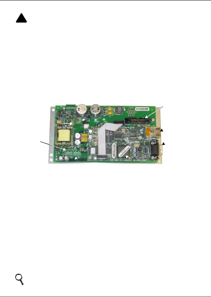
Follow these steps to install a Liebert IntelliSlot Web/485 Card With Adapter (P/N IS-WEB485ADPT).
•Locate the adapter mounting location in your Liebert equipment.
•Secure the Liebert IntelliSlot Web/485 Card With Adapter with the supplied screws.
•Connect the equipment's communication cable to the TB1 terminal block or P1 on the card (see the user manual for the Liebert power or cooling unit for details).
•Connect a Modbus (RS-485) cable to the TB2 terminal block.
•Connect an input power supply cable to Pins 1 & 2 on the TB3 terminal block; Pin 1 is at the far left, and Pin 2 is the middle pin.
TB3 (P1: +) (P2: -) 
 (P3: NC) P1 is on left
end of terminal block.
TB2 (P1: +) (P2: -); P1 is at the right side of the terminal block.
TB1 (P1: +; P2: -); P1 is at the right side of 
 the terminal block.
P1
Network Port for NMS
 and Web Access
 DB-9 Port
 MAC Address
2.2.1 Connect the Cable
1. Locate the blue serial configuration cable (null modem) that shipped with the card.
2. Connect the configuration cable to the DB-9 port on the card and to a COM port on your PC.
2.2.2 Prepare the Card for Configuration |
Table 3 |
Communication settings |
|||
1. |
Use terminal emulation software, such as |
||||
|
|
|
|||
|
Baud Rate: |
9600 |
|||
|
HyperTerminal, to open a direct connection to the card |
|
|||
|
|
Data Bits: |
8 |
||
|
with the settings in Table 3. |
|
|||
2. |
Press the Enter key for the Main Menu. |
|
Parity: |
None |
|
3. |
Select 485 Network Settings to access the |
|
Stop Bits: |
1 |
|
|
communications settings. |
|
Flow Control: |
None |
|
4.Select Enabled Application.
5.Select Modbus Server to enable the Modbus application.
6.At the next screen, select Server ID (the default Server ID is 1, but may be any number up to 255).
7.Press Esc to return to the Main Menu.
8.Select IP Network Settings, then Boot/IP Settings and follow the instructions to enter an IP ADDRESS, NETMASK and GATEWAY.
9.Press Esc to return to the Main Menu.
10.Choose Exit and Save to save your changes and reboot the card.
NOTE
When installing the card in a Liebert NX™, configure the communication port of NX to 2400 baud. See the NX user manual for details.
5
Configuration Overview
3.0CONFIGURATION OVERVIEW
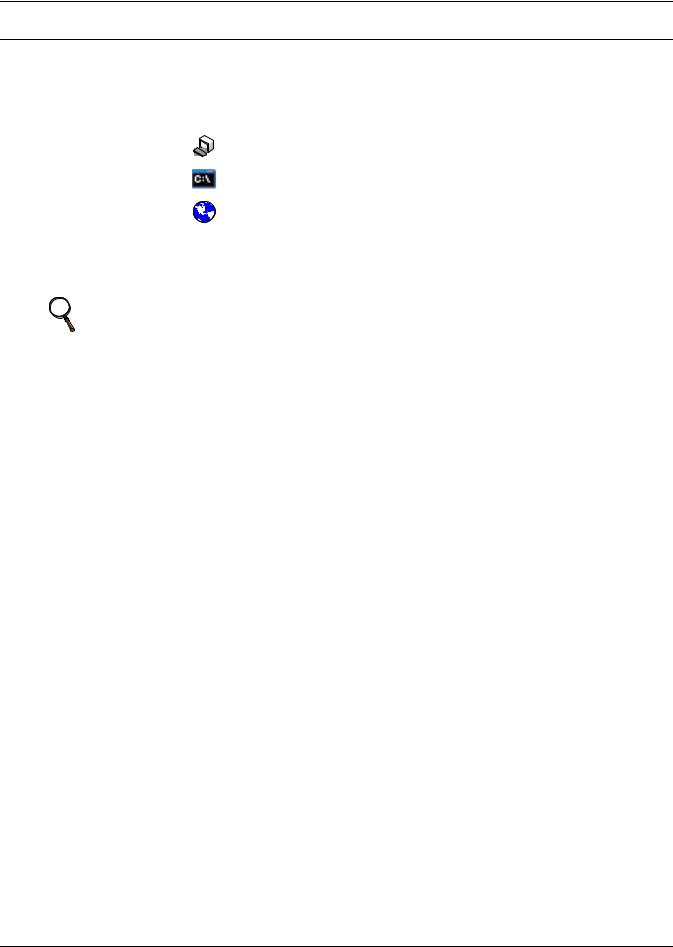
You may use any of the following interfaces to configure the Web card:
Table 4 Configuration interfaces
|
|
|
|
|
|
|
Available |
Connection |
Interface |
Icon |
Description |
Functions |
Methods |
||||
|
|
|
|
|
|
|
|
|
Terminal Emulation |
|
|
|
|
|
Use terminal emulation software |
Configuration |
Serial Cable |
|
|
|
|
|
||||
(Serial or TCP/IP) |
|
|
|
|
|
—for example, HyperTerminal. |
or TCP/IP |
|
|
|
|
|
|
|
|||
|
|
|
|
|
|
|||
|
|
|
|
|
|
|||
|
|
|
|
|
|
|
|
|
Telnet |
|
|
|
|
|
Use a command prompt—enter |
Configuration |
TCP/IP |
|
|
|
|
|
“telnet” and the IP address or hostname. |
|||
|
|
|
|
|
|
|
|
|
Web |
|
|
|
|
|
Use a Web browser—for example, |
Configuration, |
TCP/IP |
|
|
|
|
|
Microsoft® Windows® Internet Explorer®. |
Monitoring, Control |
||
Each configuration section provides instructions using the Terminal Emulation (Serial or TCP/IP Connection) / Telnet Interface, along with a brief description of how to access the same function through the Web Interface.
NOTE
The Terminal Emulation and Telnet interfaces present the same menus and choices.
3.1Guide to Configuration
Refer to the following guide for details on configuration functions. Sections 3.4 to 3.5 describe how to get started with each interface.
Table 5 |
Guide to configuration details |
|
||
|
|
|
|
|
Topic |
|
Section |
Page: |
|
|
|
|
|
|
|
|
3.2 |
- Open the Terminal Emulation Interface - Serial Connection |
7 |
|
|
|
|
|
Connecting |
3.3 |
- Open the Terminal Emulation Interface - TCP/IP Connection |
8 |
|
to an interface |
3.4 |
- Open the Telnet Interface |
9 |
|
|
|
|
|
|
|
|
3.5 |
- Open the Web Interface |
10 |
|
|
|
||
Saving configuration changes |
3.6 - Saving Changes and Reinitializing the Web Card |
10 |
||
|
|
|
|
|
|
|
4.0 |
- System Information |
11 |
|
|
|
|
|
Performing |
5.0 |
- Network Settings |
12 |
|
|
|
|
||
configuration |
6.0 |
- Messaging |
28 |
|
functions |
|
|
|
|
|
7.0 |
- Factory Settings |
34 |
|
|
|
|||
|
|
|
|
|
|
|
Appendix A - - Firmware Updates |
A1 |
|
|
|
|
|
|
6
Configuration Overview
3.2
 Open the Terminal Emulation Interface - Serial Connection
To access configuration using terminal emulation software with a serial connection to the Web card:
1.Open a terminal emulation application, such as HyperTerminal.
To do this:
•Click the Start button, then Programs, Accessories, Communications and finally HyperTerminal.
2.In the Connection Description window, enter a name for the connection—for example, GXT2U—then click OK.
3.In the Connect To window:
•Choose COM3 from the Connect Using drop-down list.
•Click OK.
4.In the COM3 Properties window, enter the communication settings shown in Table 6.
Table 6 Communication settings
Baud Rate: |
9600 |
|
|
Data Bits: |
8 |
|
|
Parity: |
None |
|
|
Stop Bits: |
1 |
|
|
Flow Control: |
None |
|
|
Name
COM3
Connection settings
5.When the message at right appears in the HyperTerminal window, press the Enter key.
6.In the Main Menu, enter the number that corresponds to your choice. Refer to 3.1 - Guide to Configuration for details on each function.
7.After making changes, return to the Main Menu and choose Exit and Save to reboot the Web card and put your changes into effect (see
3.6 - Saving Changes and Reinitializing the Web Card).
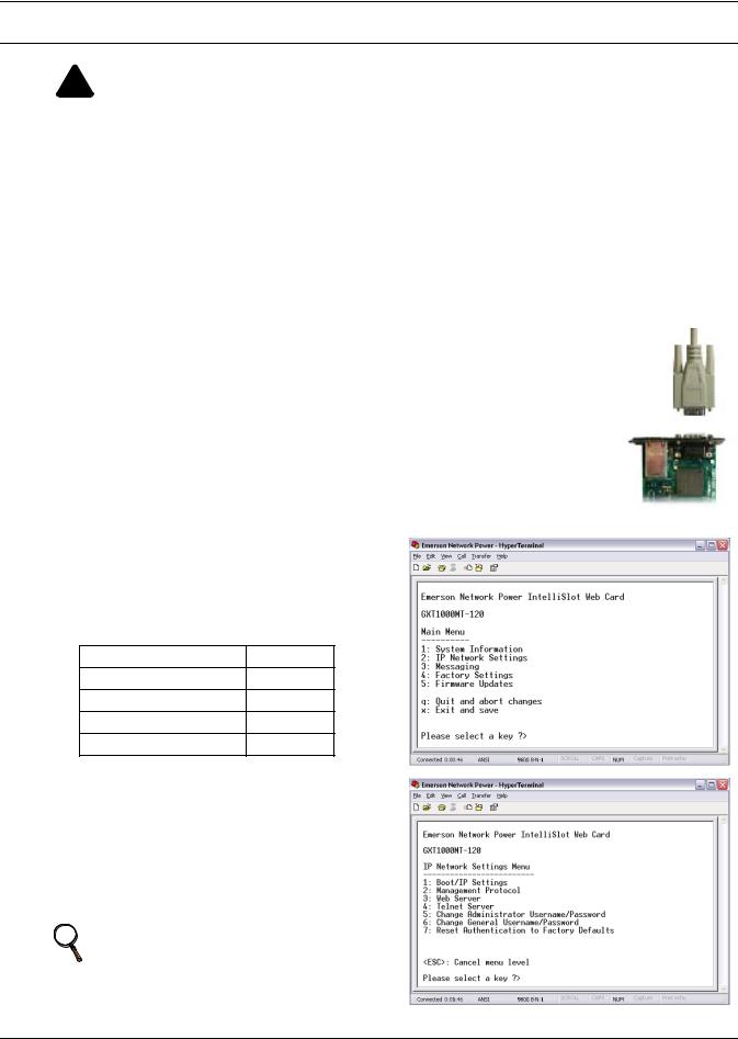
RTCS v2.96.00 Telnet server
Service Port Manager Active
<Esc> Ends Session
Main Menu
----------
1:System Information
2:IP Network Settings
3:Messaging
4:Factory Settings
5:Firmware Updates
q: Quit and abort changes x: Exit and save
Please select a key ?>
7
Configuration Overview
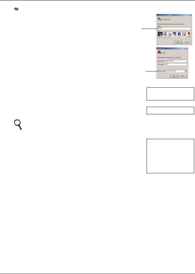
3.3
 Open the Terminal Emulation Interface - TCP/IP Connection
To access configuration using terminal emulation software with an Ethernet connection to the Web card:
1.Open a terminal emulation application, such as HyperTerminal.
To do this:
•Click the Start button, then Programs, Accessories, Communications and finally HyperTerminal.
2.In the Connection Description window, enter a name for the connection—for example, GXT2U—then click OK.
3.In the Connect To window:
•Choose TCP/IP (Winsock) from the Connect Using drop-down list.
•Enter the IP address or hostname of the Web card—for example, 192.168.0.125—in the Host Address box, then click OK.
Name
TCP/IP
(Winsock)
4.When the message at right appears in the HyperTerminal window, press the Enter key.
5.Enter the Administrator username and password (both are casesensitive):
a.Login (username—default is Liebert)
b.Password (default is Liebert)
NOTE
RTCS v2.96.00 Telnet server
Service Port Manager Active
<Esc> Ends Session
Login: Liebert
Password: ********
For security, change the default username and password (see 5.7 - Change Username / Password).
6.In the Main Menu, enter the number that corresponds to your choice. Main Menu Refer to 3.1 - Guide to Configuration for details on each function. ----------
1:System Information
7.After making changes, return to the Main Menu and choose Exit and 2: IP Network Settings
Save to reboot the Web card and put your changes into effect (see |
3: Messaging |
4: Factory Settings |
|
3.6 - Saving Changes and Reinitializing the Web Card). |
5: Firmware Updates |
|
|
|
q: Quit and abort changes |
|
x: Exit and save |
|
Please select a key ?> |
8
Configuration Overview
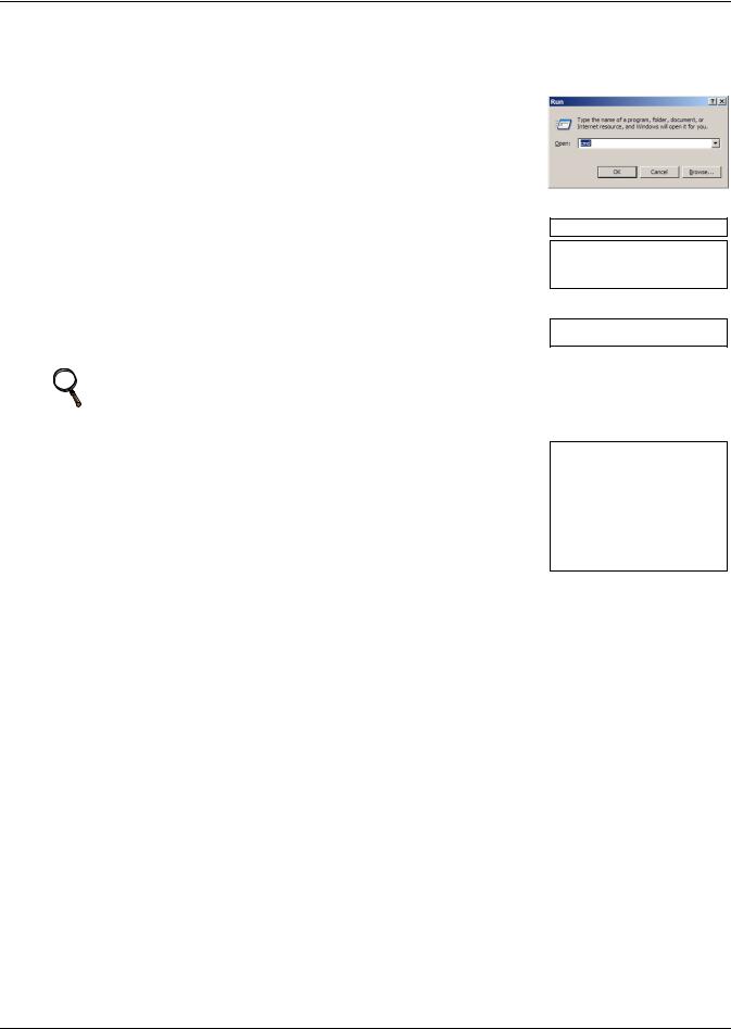
3.4 Open the Telnet Interface
To access configuration using Telnet:
1.Open a Telnet connection on a computer with an Ethernet connection to the Liebert unit. To do this:
•Open a command prompt window—click the Start button, then
Run.
•Enter cmd and click OK.
•In the command prompt window that opens, enter telnet
followed by a space and the IP address or hostname of the Web card—for example:
telnet 192.168.0.125
2.When the message at right appears in the command prompt window, press the Enter key.
3.Enter the Administrator username and password (both are casesensitive):
a.Login (username—default is Liebert)
b.Password (default is Liebert)
NOTE
C:>telnet 192.168.0.125
RTCS v2.96.00 Telnet server
Service Port Manager Active
<Esc> Ends Session
Login: Liebert
Password: ********
For security, change the default username and password (see 5.7 - Change Username / Password).
4.In the Main Menu, enter the number that corresponds to your choice. Main Menu Refer to 3.1 - Guide to Configuration for details on each function. ----------
1:System Information
5. After making changes, return to the Main Menu and choose Exit and |
2: IP Network Settings |
|
Save to reboot the Web card and put your changes into effect (see |
3: Messaging |
|
4: Factory Settings |
||
3.6 - Saving Changes and Reinitializing the Web Card). |
5: Firmware Updates |
|
q: Quit and abort changes |
||
|
||
|
x: Exit and save |
|
|
Please select a key ?> |
9
Configuration Overview
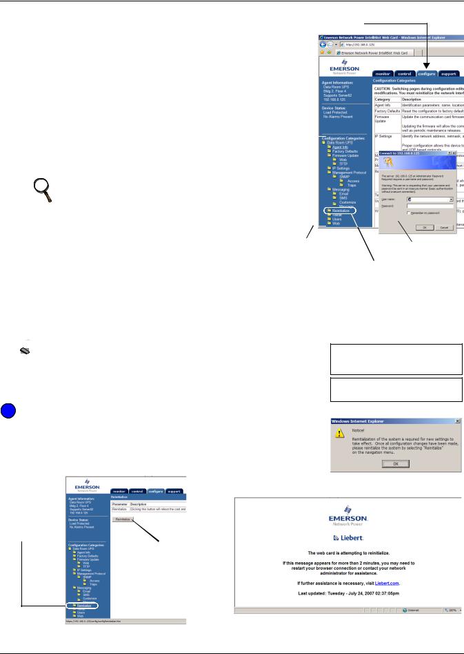
3.5 Open the Web Interface
To access configuration using the Web interface:
1.Open a Web browser such as Internet Explorer, then enter the IP address or hostname of the Web card in the address bar—e.g., http://192.168.0.125.
2.Click on the Configure tab, shown at right. Configuration Categories appear in the left panel, organized with folder icons.
3.Click on any configuration category, and the Connect To box opens.
4.Enter the Administrator username and password (both case-sensitive):
a.User Name (default is Liebert)
b.Password (default is Liebert)
NOTE
For security, change the default username and password (see 5.7 - Change Username / Password).
5.Click OK.
6.Refer to 3.1 - Guide to Configuration for details on each function.
7.After making changes, click the Save button, then click on Reinitialize to reboot the Web card and put your changes into effect (see 3.6 - Saving Changes and Reinitializing the Web Card).
Configure tab
|
|
|
|
|
|
|
|
|
|
Configuration |
|
|||
Connect To |
||||
Categories |
||||
|
||||
Reinitialize
(to save any changes)
3.6Saving Changes and Reinitializing the Web Card
Follow the applicable steps for your interface to save configuration changes and reinitialize the Web card. Changes will not take effect until these steps are completed.


 Terminal Emulation (Serial or TCP/IP Connection) / Telnet
•After each change is made, a reminder appears (shown at right).
•Return to the Main Menu, then choose Exit and Save. A message appears and remains until the card is reinitialized, followed by a message that the process was successful.
New Settings will take effect when saved
GO TO MAIN MENU AND DO 'EXIT AND SAVE' TO SAVE YOUR CHANGES!
Exiting and saving...
Configuration saved successfully
 Web Interface
•After making each change, click the Save button. A reminder appears each time you make a change (shown at right).
•Without leaving the Configure tab window (below left), click Reinitialize in the left panel, then click the Reinitialize button at right to reboot the Web card and put your changes into effect.
Progress message window
First click Reinitialize at left
Then click Reinitialize button
• A message window appears, shown above right, and remains until the card is reinitialized.
10
System Information
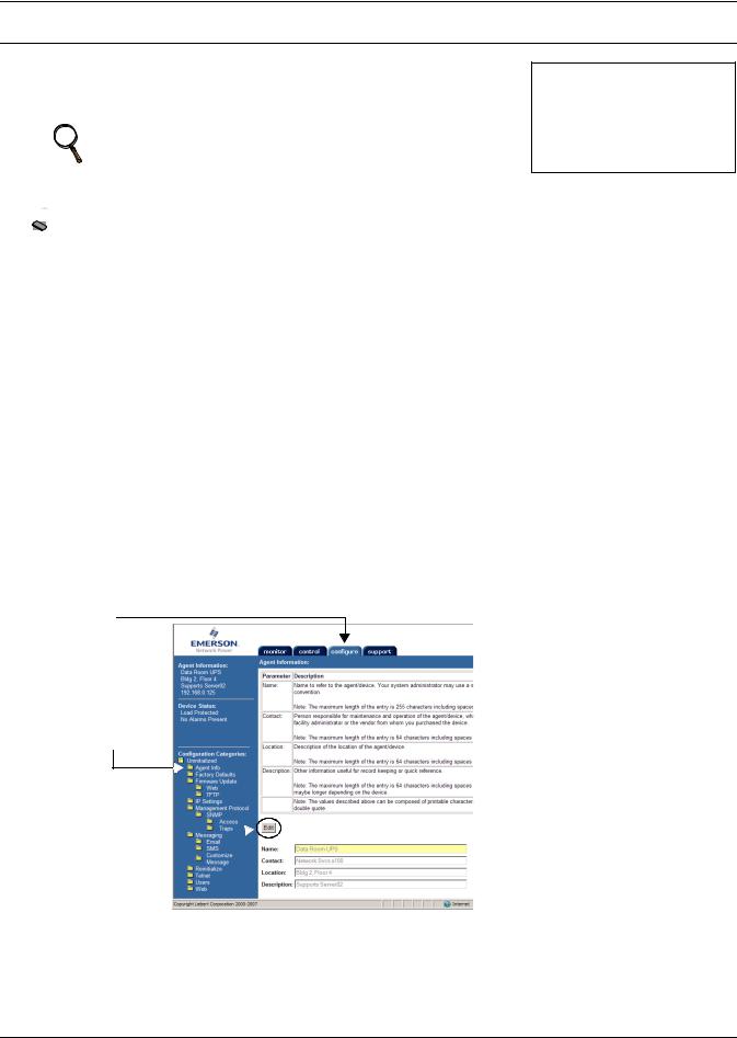
4.0SYSTEM INFORMATION
System Information is optional and identifies the Liebert unit, its location, a contact person and other information about the unit. The default value of each field is “Uninitialized.”
NOTE
This information also configures the SNMP parameters sysName, sysContact, sysDescr, and sysLocation available using RFC-1213 MIB II.
System Information Menu
------------------------
1: Name |
Uninitialized |
2: Contact |
Uninitialized |
3: Location |
Uninitialized |
4: Description |
Uninitialized |
<ESC>: Cancel menu level Please select a key ?>


 Terminal Emulation (Serial or TCP/IP Connection) / Telnet
To edit any field in this category:
1.From the Main Menu, choose System Information.
2.Enter the number that corresponds to your choice, then enter the identifying information, using the following as a guide.
Table 7 |
System information identifiers |
|
||
|
|
|
|
|
Item |
|
Description |
Maximum Length |
|
|
|
|
|
|
Name |
|
A name for the Liebert unit |
255 characters* |
|
|
|
|
|
|
Contact |
|
A contact person or department responsible |
64 characters* |
|
|
for maintenance and operation of the Liebert unit |
|||
|
|
|
||
Location |
|
The location of the Liebert unit |
64 characters* |
|
|
|
|
|
|
Description |
Other useful information about the unit |
64 characters* |
||
for quick reference |
||||
|
|
|
||
* Valid characters include spaces and other printable characters except double quotes (").
 Web Interface
To access System Information through the Web interface:
•Click on the Configure tab, then Agent Info in the left panel and finally Edit in the right panel. After making changes, click Save.
Configure tab
Agent
Info
Edit 
11

Network Settings
5.0NETWORK SETTINGS
The IP Network Settings Menu is used to enable network communications with the Web card.
Refer to the following sections for detailed step-by-step instructions on each item from this menu:
Table 8 |
Network Settings menu guide |
|
|
|
|
|
|
Menu item |
|
Refer to: |
|
|
|
|
|
5.1 |
- Boot/IP Settings |
page 13 |
|
|
|
|
|
5.2 |
- Domain Name Server (DNS) Settings |
page 14 |
|
|
|
|
|
5.3 |
- Management Protocol |
page 15 |
|
|
|
|
|
5.4 |
- Web Server |
page 19 |
|
|
|
|
|
5.5 |
- Telnet Server |
page 24 |
|
|
|
|
|
5.6 |
- Time (SNTP) Menu |
page 24 |
|
|
|
|
|
5.7 |
- Change Username / Password |
page 26 |
|
|
|
|
|
5.8 |
- Reset Authentication to Factory Defaults |
page 27 |
|
|
|
|
|
IP Network Settings Menu
-------------------------
1:Boot/IP Settings
2:Domain Name Server (DNS) Settings
3:Management Protocol
4:Web Server
5:Telnet Server
6:Time (SNTP)
7. Change Administrator Username/Password
8:Change General Username/Password
9:Reset Authentication to Factory Defaults
<ESC>: Cancel menu level Please select a key ?>
12
Network Settings
5.1Boot/IP Settings
The Boot/IP Settings Menu is used to set parameters for network access to the Web card. Consult your network administrator for these settings.


 Terminal Emulation (Serial or TCP/IP Connection) / Telnet
To change any parameter:
Boot/IP Settings Menu
----------------------
1: Speed/Duplex |
Auto |
2: Boot mode |
Static |
3: IP Address |
192.168.0.125 |
4: Netmask |
255.255.255.0 |
5: Default Gateway |
192.168.0.1 |
6: DNS Server |
0.0.0.0 |
<ESC>: Cancel menu level Please select a key ?>
1.Choose IP Network Settings from the Main Menu, then Boot/IP Settings.
2.Select an option to change—for example, Speed/Duplex, then enter settings according to the following guide.
Table 9 |
Boot/IP settings range |
|
||
|
|
|
||
Parameter |
|
Description & Valid Settings* |
||
|
|
Speed and duplex configuration of the Ethernet port. |
||
Speed/ Duplex |
• Auto (default—use this setting if unknown) |
|||
• 10Mbs/Half Duplex |
• 100Mbs/Half Duplex |
|||
|
|
|||
|
|
• 10Mbs/Full Duplex |
• 100Mbs/Full Duplex |
|
|
|
Startup mode enabling the Web card to be a network-ready device. |
||
Boot Mode |
|
• Static - Fixed network addresses and other parameters |
||
|
• DHCP - Central management using dynamic network addresses |
|||
|
|
|||
|
|
• BootP - Older mechanism for central management of network addresses |
||
IP address |
|
Network address for the Liebert unit. |
||
|
Four numbers (0-255) separated by periods (.)—for example, 10.0.0.5 |
|||
|
|
|||
Netmask |
|
Network mask that divides your network into manageable segments. |
||
|
Four numbers (0-255) separated by periods (.)—e.g., 255.255.255.0 |
|||
|
|
|||
Default Gateway |
IP address of the gateway for network traffic to other networks or subnets. |
|||
Four numbers (0-255) separated by periods (.)—e.g., 10.0.0.1 |
||||
|
|
|||
DHCP/BootP Server |
Device on a network that assigns IP addresses that are not static. |
|||
Four numbers (0-255) separated by periods (.)—for example, 192.168.0.5 |
||||
|
|
|||
DNS Server |
IP address of the Domain Name Server for the network. |
|||
Four numbers (0-255) separated by periods (.)—e.g., 10.0.0.1 |
||||
|
|
|||
* Consult your network administrator for proper settings.
 Web Interface
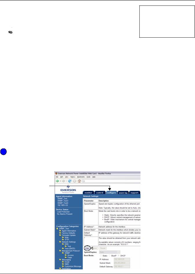
To access Boot/IP Settings through the Web interface:
•Click on the Configure tab, then Network Settings in the left panel and finally Edit beneath the table of parameters and descriptions. After making changes, click Save.
Configure tab
Network 

Settings
 Edit
Edit
13

Network Settings
5.2Domain Name Server (DNS) Settings
The Domain Name Server settings menu configures the servers the Web card will use for hostname resolution. When configured, host addresses for SNMP, Network Time and Email/SMS can be specified in either full Domain Name format or in host-only format, provided that the appropriate Domain Name Suffix is used.
The DNS menu is used to set parameters for network access to the Web card. Consult your network administrator for these settings.


 Terminal Emulation (Serial or TCP/IP Connection) / Telnet
To change any parameter:
1.Choose IP Network Settings from the Main Menu, then Domain Name Server (DNS) Settings.
2.Select an option to change—for example, DNS Mode, then enter settings according to the following guide.
Table 10 Domain Name Server settings
Parameter |
Description & Valid Settings* |
|
|
|
|
DNS Mode |
Obtain DNS server addresses automatically or use specified addresses. |
|
Note: Automatic assignment option is available only if a DHCP server is used to assign |
||
|
IP information to the Web Card. |
|
Primary DNS |
Primary IP address of the name server for network.* |
|
Four numbers (0-255) separated by periods (.)—e.g., 192.168.0.1 |
||
|
||
Secondary DNS |
Secondary IP address of the name server for network.* |
|
Four numbers (0-255) separated by periods (.)—e.g., 192.168.0.1 |
||
|
||
DNS Resolve Interval |
Interval to resolve DNS addresses from a network name to an IP address. |
|
|
|
|
Domain Name Suffix |
This suffix is used for assembling a fully qualified domain name when a host-only name |
|
is specified. |
||
|
||
|
Checks whether the Web card will resolve a hostname to an IP address. Provide a host- |
|
DNS Test |
only name, a fully qualified domain name or an IP address, click on Query for the card to |
|
|
attempt a lookup with the provided information. |
* Consult your network administrator for proper settings.
14
Loading...