


 Loading...


 Precision Cooling


 For Business-Critical Continuity™


 Liebert® iCOM™


 User Manual - Intelligent Communications & Monitoring


TABLE OF CONTENTS
1.0 INTRODUCTION . . . . . . . . . . . . . . . . . . . . . . . . . . . . . . . . . . . . . . . . . . . . . . . . . . . . . . . . . .1
1.1 Features . . . . . . . . . . . . . . . . . . . . . . . . . . . . . . . . . . . . . . . . . . . . . . . . . . . . . . . . . . . . . . . . . . . 1
2.0 LIEBERT ICOM DISPLAY COMPONENTS AND FUNCTIONS . . . . . . . . . . . . . . . . . . . . . . . . . . .2
2.1 Navigating Through the Liebert iCOM Menus . . . . . . . . . . . . . . . . . . . . . . . . . . . . . . . . . . . . 5
2.1.1 Control Interface. . . . . . . . . . . . . . . . . . . . . . . . . . . . . . . . . . . . . . . . . . . . . . . . . . . . . . . . . . . . . . 5 2.1.2 Accessing Submenus . . . . . . . . . . . . . . . . . . . . . . . . . . . . . . . . . . . . . . . . . . . . . . . . . . . . . . . . . . 5 2.1.3 Entering a Password . . . . . . . . . . . . . . . . . . . . . . . . . . . . . . . . . . . . . . . . . . . . . . . . . . . . . . . . . . 6 2.1.4 Viewing Multiple Units with a Networked Large Display. . . . . . . . . . . . . . . . . . . . . . . . . . . . . 8
3.0 OPERATION . . . . . . . . . . . . . . . . . . . . . . . . . . . . . . . . . . . . . . . . . . . . . . . . . . . . . . . . . . .12
3.1 Single Unit Functions . . . . . . . . . . . . . . . . . . . . . . . . . . . . . . . . . . . . . . . . . . . . . . . . . . . . . . . 12
3.1.1 Unit/Fan Control . . . . . . . . . . . . . . . . . . . . . . . . . . . . . . . . . . . . . . . . . . . . . . . . . . . . . . . . . . . . 12 3.1.2 Chilled Water Units with Variable Speed Motor . . . . . . . . . . . . . . . . . . . . . . . . . . . . . . . . . . . 13 3.1.3 General Compressor Requirements. . . . . . . . . . . . . . . . . . . . . . . . . . . . . . . . . . . . . . . . . . . . . . 14 3.1.4 Compressor Timing—Units With Two Compressors . . . . . . . . . . . . . . . . . . . . . . . . . . . . . . . . 15 3.1.5 Compressor Sequencing . . . . . . . . . . . . . . . . . . . . . . . . . . . . . . . . . . . . . . . . . . . . . . . . . . . . . . . 15
3.2 Motorized Ball Valve in Digital Scroll Units . . . . . . . . . . . . . . . . . . . . . . . . . . . . . . . . . . . . . 16
3.2.1 MBV Operation After Compressor is Turned Off . . . . . . . . . . . . . . . . . . . . . . . . . . . . . . . . . . . 16 3.2.2 Service Offset—Changing System Pressure Settings . . . . . . . . . . . . . . . . . . . . . . . . . . . . . . . 16
3.3 Temperature Control—Single Source Cooling (No Extra Cooling Coil) . . . . . . . . . . . . . . . . 17
3.3.1 Temperature Proportional Band . . . . . . . . . . . . . . . . . . . . . . . . . . . . . . . . . . . . . . . . . . . . . . . . 17 3.3.2 Compressor Control . . . . . . . . . . . . . . . . . . . . . . . . . . . . . . . . . . . . . . . . . . . . . . . . . . . . . . . . . . 18 3.3.3 Chilled Water Control . . . . . . . . . . . . . . . . . . . . . . . . . . . . . . . . . . . . . . . . . . . . . . . . . . . . . . . . 21
3.4 Temperature Control—Second Cooling Source . . . . . . . . . . . . . . . . . . . . . . . . . . . . . . . . . . . 21
3.4.1 Differential Temperatures / Controls (Comparator Circuit) . . . . . . . . . . . . . . . . . . . . . . . . . . 21
3.5 Temperature Control—Reheat . . . . . . . . . . . . . . . . . . . . . . . . . . . . . . . . . . . . . . . . . . . . . . . . 23
3.5.1 Three-Stage Electric, Hot Gas and Hot Water Reheat. . . . . . . . . . . . . . . . . . . . . . . . . . . . . . . 23 3.5.2 SCR Reheat. . . . . . . . . . . . . . . . . . . . . . . . . . . . . . . . . . . . . . . . . . . . . . . . . . . . . . . . . . . . . . . . . 25
3.6 Humidity Control . . . . . . . . . . . . . . . . . . . . . . . . . . . . . . . . . . . . . . . . . . . . . . . . . . . . . . . . . . . 27
3.6.1 Humidification . . . . . . . . . . . . . . . . . . . . . . . . . . . . . . . . . . . . . . . . . . . . . . . . . . . . . . . . . . . . . . 28 3.6.2 Dehumidification . . . . . . . . . . . . . . . . . . . . . . . . . . . . . . . . . . . . . . . . . . . . . . . . . . . . . . . . . . . . 29
3.7 Control Types . . . . . . . . . . . . . . . . . . . . . . . . . . . . . . . . . . . . . . . . . . . . . . . . . . . . . . . . . . . . . . 30
3.7.1 Temperature and Humidity Control Types. . . . . . . . . . . . . . . . . . . . . . . . . . . . . . . . . . . . . . . . 30 3.7.2 Humidity Sensor Reading Control Types . . . . . . . . . . . . . . . . . . . . . . . . . . . . . . . . . . . . . . . . . 31 3.7.3 Supply Limit—Optional . . . . . . . . . . . . . . . . . . . . . . . . . . . . . . . . . . . . . . . . . . . . . . . . . . . . . . . 32 3.7.4 High and Low, Temperature and Humidity Events. . . . . . . . . . . . . . . . . . . . . . . . . . . . . . . . . 32 3.7.5 User Inputs / Customer Inputs . . . . . . . . . . . . . . . . . . . . . . . . . . . . . . . . . . . . . . . . . . . . . . . . . 33 3.7.6 Event Types and Properties. . . . . . . . . . . . . . . . . . . . . . . . . . . . . . . . . . . . . . . . . . . . . . . . . . . . 34
3.8 Possible Event Notifications . . . . . . . . . . . . . . . . . . . . . . . . . . . . . . . . . . . . . . . . . . . . . . . . . . 36
i

3.9 Next Maintenance Calculation . . . . . . . . . . . . . . . . . . . . . . . . . . . . . . . . . . . . . . . . . . . . . . . . 37
3.9.1 Calculation of Next Maintenance and Diagnostics. . . . . . . . . . . . . . . . . . . . . . . . . . . . . . . . . . 37
4.0 TEAMWORK . . . . . . . . . . . . . . . . . . . . . . . . . . . . . . . . . . . . . . . . . . . . . . . . . . . . . . . . . . .39
4.1 Teamwork Modes . . . . . . . . . . . . . . . . . . . . . . . . . . . . . . . . . . . . . . . . . . . . . . . . . . . . . . . . . . . 39
4.1.1 Application of Teamwork Modes . . . . . . . . . . . . . . . . . . . . . . . . . . . . . . . . . . . . . . . . . . . . . . . . 39
4.1.2 No Teamwork . . . . . . . . . . . . . . . . . . . . . . . . . . . . . . . . . . . . . . . . . . . . . . . . . . . . . . . . . . . . . . . 39
4.1.3 Teamwork Mode 1 . . . . . . . . . . . . . . . . . . . . . . . . . . . . . . . . . . . . . . . . . . . . . . . . . . . . . . . . . . . 39
4.1.4 Teamwork Mode 2 . . . . . . . . . . . . . . . . . . . . . . . . . . . . . . . . . . . . . . . . . . . . . . . . . . . . . . . . . . . 41
4.1.5 Standby – Rotation . . . . . . . . . . . . . . . . . . . . . . . . . . . . . . . . . . . . . . . . . . . . . . . . . . . . . . . . . . . 41
5.0 INSTALLING A LIEBERT ICOM UNIT-TO-UNIT NETWORK . . . . . . . . . . . . . . . . . . . . . . . . . . .42
5.1 Placement of Cooling Units . . . . . . . . . . . . . . . . . . . . . . . . . . . . . . . . . . . . . . . . . . . . . . . . . . . 42 5.2 U2U Hardware: Cables and Network Switch . . . . . . . . . . . . . . . . . . . . . . . . . . . . . . . . . . . . . 42 5.3 Wiring for Unit-to-Unit Communications—U2U . . . . . . . . . . . . . . . . . . . . . . . . . . . . . . . . . . 43
5.3.1 Wiring a Liebert iCOM U2U Network . . . . . . . . . . . . . . . . . . . . . . . . . . . . . . . . . . . . . . . . . . . 44
5.4 External Communications—Building Management Systems, Liebert SiteScan® . . . . . . . . . . . 48
6.0 MOUNTING A LARGE DISPLAY ON A WALL . . . . . . . . . . . . . . . . . . . . . . . . . . . . . . . . . . . .49
6.0.1 Location Considerations. . . . . . . . . . . . . . . . . . . . . . . . . . . . . . . . . . . . . . . . . . . . . . . . . . . . . . . 49
7.0 USER MENU PARAMETERS . . . . . . . . . . . . . . . . . . . . . . . . . . . . . . . . . . . . . . . . . . . . . . . .51
8.0 SERVICE MENU PARAMETERS. . . . . . . . . . . . . . . . . . . . . . . . . . . . . . . . . . . . . . . . . . . . . .56
ii

FIGURES
Figure 1 Liebert iCOM components . . . . . . . . . . . . . . . . . . . . . . . . . . . . . . . . . . . . . . . . . . . . . . . . . . . . . . . . . 1 Figure 2 Liebert iCOM display components. . . . . . . . . . . . . . . . . . . . . . . . . . . . . . . . . . . . . . . . . . . . . . . . . . . 2 Figure 3 Status menu, large display, graphical view. . . . . . . . . . . . . . . . . . . . . . . . . . . . . . . . . . . . . . . . . . . . 4 Figure 4 Liebert iCOM default screen symbols . . . . . . . . . . . . . . . . . . . . . . . . . . . . . . . . . . . . . . . . . . . . . . . . 4 Figure 5 Menu tree—Small display, stand-alone or networked . . . . . . . . . . . . . . . . . . . . . . . . . . . . . . . . . . . 6 Figure 6 Menu tree—Large display, stand-alone. . . . . . . . . . . . . . . . . . . . . . . . . . . . . . . . . . . . . . . . . . . . . . . 7 Figure 7 Menu tree—Large display, networked. . . . . . . . . . . . . . . . . . . . . . . . . . . . . . . . . . . . . . . . . . . . . . . . 8 Figure 8 User menu icons . . . . . . . . . . . . . . . . . . . . . . . . . . . . . . . . . . . . . . . . . . . . . . . . . . . . . . . . . . . . . . . . . 9 Figure 9 Service menu icons . . . . . . . . . . . . . . . . . . . . . . . . . . . . . . . . . . . . . . . . . . . . . . . . . . . . . . . . . . . . . . 11 Figure 10 Start-stop priority switches . . . . . . . . . . . . . . . . . . . . . . . . . . . . . . . . . . . . . . . . . . . . . . . . . . . . . . . 12 Figure 11 Temperature proportional band. . . . . . . . . . . . . . . . . . . . . . . . . . . . . . . . . . . . . . . . . . . . . . . . . . . . 17 Figure 12 One single-step compressor without unloaders. . . . . . . . . . . . . . . . . . . . . . . . . . . . . . . . . . . . . . . . 18
Figure 13 Two single-step compressors without unloaders or one compressor with an unloader
(two-step) . . . . . . . . . . . . . . . . . . . . . . . . . . . . . . . . . . . . . . . . . . . . . . . . . . . . . . . . . . . . . . . . . . . . . . 18 Figure 14 Two compressors with unloaders (four-step). . . . . . . . . . . . . . . . . . . . . . . . . . . . . . . . . . . . . . . . . . 19 Figure 15 Digital scroll capacity modulation, 10-100% variable. . . . . . . . . . . . . . . . . . . . . . . . . . . . . . . . . . . 20 Figure 16 Single and dual digital scroll compressor activation points . . . . . . . . . . . . . . . . . . . . . . . . . . . . . . 20 Figure 17 Three-point actuator control (example: cooling) . . . . . . . . . . . . . . . . . . . . . . . . . . . . . . . . . . . . . . . 21 Figure 18 Second cooling source and compressorized cooling . . . . . . . . . . . . . . . . . . . . . . . . . . . . . . . . . . . . . 22 Figure 19 Three-stage heating . . . . . . . . . . . . . . . . . . . . . . . . . . . . . . . . . . . . . . . . . . . . . . . . . . . . . . . . . . . . . 24 Figure 20 Two single-step compressors with SCR reheat set to Tight mode . . . . . . . . . . . . . . . . . . . . . . . . . 25 Figure 21 Two single-step compressors with SCR reheat set to Standard mode. . . . . . . . . . . . . . . . . . . . . . 26 Figure 22 Humidity proportional band. . . . . . . . . . . . . . . . . . . . . . . . . . . . . . . . . . . . . . . . . . . . . . . . . . . . . . . 27 Figure 23 Teamwork Mode 1 with two cooling units . . . . . . . . . . . . . . . . . . . . . . . . . . . . . . . . . . . . . . . . . . . . 40 Figure 24 Connecting two cooling units, each with a small display using a crossover Ethernet cable . . . . 44 Figure 25 Wiring a small display for stand-alone operation . . . . . . . . . . . . . . . . . . . . . . . . . . . . . . . . . . . . . . 45 Figure 26 Wiring a small display for U2U network operation . . . . . . . . . . . . . . . . . . . . . . . . . . . . . . . . . . . . 45 Figure 27 Wiring a large display for stand-alone operation . . . . . . . . . . . . . . . . . . . . . . . . . . . . . . . . . . . . . . 46 Figure 28 Wiring a large display for U2U network operation. . . . . . . . . . . . . . . . . . . . . . . . . . . . . . . . . . . . . 46 Figure 29 Liebert iCOM input-output control board . . . . . . . . . . . . . . . . . . . . . . . . . . . . . . . . . . . . . . . . . . . . 47 Figure 30 Liebert vNSA with optional remote large display. . . . . . . . . . . . . . . . . . . . . . . . . . . . . . . . . . . . . . 48 Figure 31 Liebert iCOM display dimensions . . . . . . . . . . . . . . . . . . . . . . . . . . . . . . . . . . . . . . . . . . . . . . . . . . 50
iii

TABLES
Table 1 Keyboard icons and functions. . . . . . . . . . . . . . . . . . . . . . . . . . . . . . . . . . . . . . . . . . . . . . . . . . . . . . . 3 Table 2 User menu icons . . . . . . . . . . . . . . . . . . . . . . . . . . . . . . . . . . . . . . . . . . . . . . . . . . . . . . . . . . . . . . . . . 9 Table 3 Service menu icons . . . . . . . . . . . . . . . . . . . . . . . . . . . . . . . . . . . . . . . . . . . . . . . . . . . . . . . . . . . . . . 11 Table 4 Reheat configuration types. . . . . . . . . . . . . . . . . . . . . . . . . . . . . . . . . . . . . . . . . . . . . . . . . . . . . . . . 23 Table 5 Parameters for infrared humidifier control. . . . . . . . . . . . . . . . . . . . . . . . . . . . . . . . . . . . . . . . . . . 28 Table 6 Dehumidification With Comp settings. . . . . . . . . . . . . . . . . . . . . . . . . . . . . . . . . . . . . . . . . . . . . . . 29 Table 7 Customer inputs . . . . . . . . . . . . . . . . . . . . . . . . . . . . . . . . . . . . . . . . . . . . . . . . . . . . . . . . . . . . . . . . 33 Table 8 Possible event settings—some events not available in all units . . . . . . . . . . . . . . . . . . . . . . . . . . 35 Table 9 Event notifications—large or small display . . . . . . . . . . . . . . . . . . . . . . . . . . . . . . . . . . . . . . . . . . 36 Table 10 Sample Liebert iCOM network configurations . . . . . . . . . . . . . . . . . . . . . . . . . . . . . . . . . . . . . . . . 43 Table 11 Ports available for connecting Liebert iCOM control devices. . . . . . . . . . . . . . . . . . . . . . . . . . . . . 47 Table 12 Setpoints parameters . . . . . . . . . . . . . . . . . . . . . . . . . . . . . . . . . . . . . . . . . . . . . . . . . . . . . . . . . . . . 51 Table 13 Spare part list parameters—large display only . . . . . . . . . . . . . . . . . . . . . . . . . . . . . . . . . . . . . . . 51 Table 14 Event log parameters . . . . . . . . . . . . . . . . . . . . . . . . . . . . . . . . . . . . . . . . . . . . . . . . . . . . . . . . . . . . 51 Table 15 View network parameters—large display only* . . . . . . . . . . . . . . . . . . . . . . . . . . . . . . . . . . . . . . . 51 Table 16 Sensor data . . . . . . . . . . . . . . . . . . . . . . . . . . . . . . . . . . . . . . . . . . . . . . . . . . . . . . . . . . . . . . . . . . . . 52 Table 17 Set alarms parameters . . . . . . . . . . . . . . . . . . . . . . . . . . . . . . . . . . . . . . . . . . . . . . . . . . . . . . . . . . 52 Table 18 Active alarms parameters . . . . . . . . . . . . . . . . . . . . . . . . . . . . . . . . . . . . . . . . . . . . . . . . . . . . . . . . 53 Table 19 Display setup parameters. . . . . . . . . . . . . . . . . . . . . . . . . . . . . . . . . . . . . . . . . . . . . . . . . . . . . . . . . 53 Table 20 Timer parameters—Sleep Mode. . . . . . . . . . . . . . . . . . . . . . . . . . . . . . . . . . . . . . . . . . . . . . . . . . . . 54 Table 21 Total run hours parameters . . . . . . . . . . . . . . . . . . . . . . . . . . . . . . . . . . . . . . . . . . . . . . . . . . . . . . . 54 Table 22 Service contacts parameters. . . . . . . . . . . . . . . . . . . . . . . . . . . . . . . . . . . . . . . . . . . . . . . . . . . . . . . 55 Table 23 Setpoints parameters . . . . . . . . . . . . . . . . . . . . . . . . . . . . . . . . . . . . . . . . . . . . . . . . . . . . . . . . . . . . 56 Table 24 Unit diary parameters . . . . . . . . . . . . . . . . . . . . . . . . . . . . . . . . . . . . . . . . . . . . . . . . . . . . . . . . . . . 57 Table 25 Maintenance / wellness settings parameters . . . . . . . . . . . . . . . . . . . . . . . . . . . . . . . . . . . . . . . . . 58 Table 26 Standby settings / lead-lag parameters . . . . . . . . . . . . . . . . . . . . . . . . . . . . . . . . . . . . . . . . . . . . . . 58 Table 27 Diagnostics / service mode parameters . . . . . . . . . . . . . . . . . . . . . . . . . . . . . . . . . . . . . . . . . . . . . . 61 Table 28 Set alarms parameters . . . . . . . . . . . . . . . . . . . . . . . . . . . . . . . . . . . . . . . . . . . . . . . . . . . . . . . . . . 63 Table 29 Sensor calibration / setup parameters . . . . . . . . . . . . . . . . . . . . . . . . . . . . . . . . . . . . . . . . . . . . . . . 69 Table 30 System / network setup parameters—large display only . . . . . . . . . . . . . . . . . . . . . . . . . . . . . . . . 70 Table 31 Network setup parameters. . . . . . . . . . . . . . . . . . . . . . . . . . . . . . . . . . . . . . . . . . . . . . . . . . . . . . . . 71 Table 32 Options setup parameters . . . . . . . . . . . . . . . . . . . . . . . . . . . . . . . . . . . . . . . . . . . . . . . . . . . . . . . . 73 Table 33 Service contact info parameters . . . . . . . . . . . . . . . . . . . . . . . . . . . . . . . . . . . . . . . . . . . . . . . . . . . . 74
iv
Introduction
1.0INTRODUCTION
The Liebert iCOM™ control offers the highest capabilities in unit control, communication and monitoring of Liebert mission-critical cooling units.
Liebert iCOM may be used to combine multiple cooling units into a team that operates as a single entity, enhancing the already-high performance and efficiency of Liebert’s units.
Liebert iCOM is available as a factory-installed assembly or may be retrofitted on existing products with SM, AM or AG controls. Large graphic display wall-mount versions of the control are available for remote operation and monitoring of cooling units.
1.1Features
Large and Small Displays
The Liebert iCOM control is available with either a large or small liquid crystal display.
•The Liebert iCOM with small display has a 128 x 64 dot matrix screen that simultaneously shows two menu icons, along with descriptive text. This display is capable of controlling only the unit it is directly connected to.
•The Liebert iCOM with large display has a 320 x 240 dot matrix screen that shows up to 16 menu icons at a time, as well as descriptive text. This display can be used to control a single cooling unit or any cooling unit on a network, regardless of how it is connected—either integrated into a cooling unit or simply connected to the network and mounted remotely.
Liebert iCOM’s menu-driven display is used for all programming functions on each connected cooling unit. The Status menu shows the status of the conditioned space, such as room temperature and humidity, temperature and humidity setpoints, alarm status and settings, event histories and the current time.
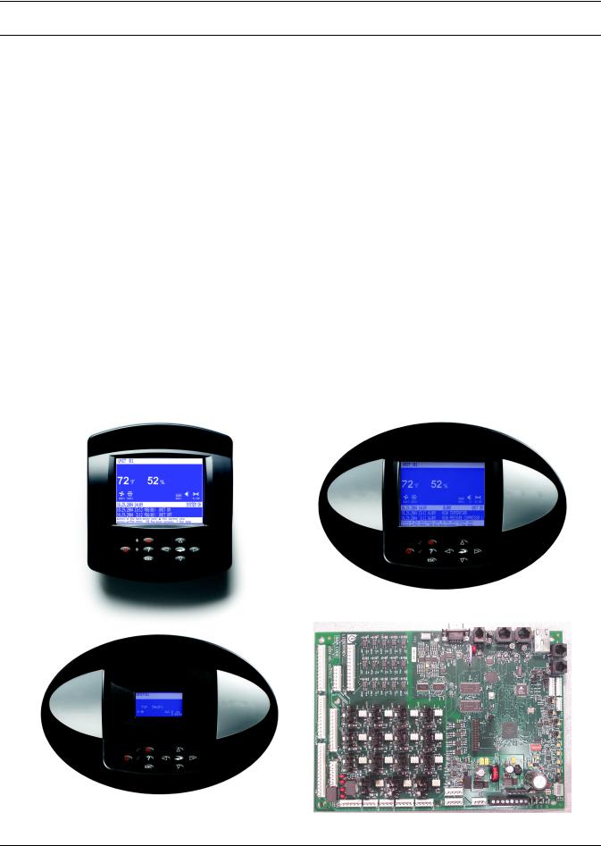
Figure 1 Liebert iCOM components
Wall Mount Large Display |
Direct Panel Mount Large Display and Bezel |
|
Direct Panel Mount |
Liebert iCOM Input/Output Board |
|
Small Display and Bezel |
||
|
1
Liebert iCOM Display Components and Functions
2.0LIEBERT ICOM DISPLAY COMPONENTS AND FUNCTIONS
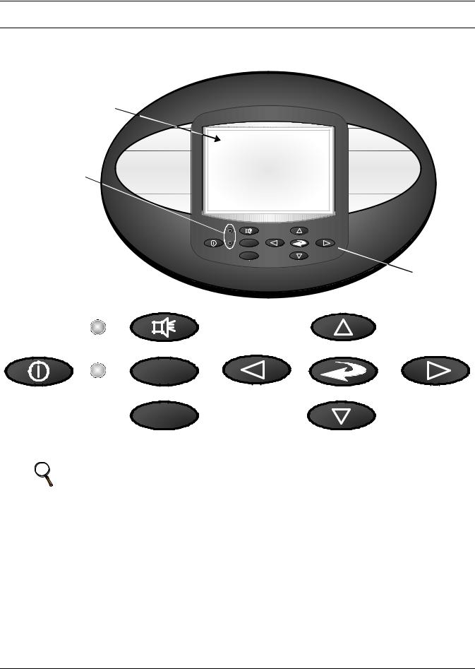
The small and the large display have a common key layout, as shown in Figure 2.
Figure 2 Liebert iCOM display components
Liquid Crystal Display
LED Status Indicators (top LED is red or  flashing red; bottom LED is green or amber)
Large Liebert iCOM Display shown - Keypad and LEDs are identical on all displays.
?
E S C
Keypad
|
Alarm Key |
|
Up Arrow Key |
|
|
? |
|
|
|
On/Off Key |
Help Key |
Left Arrow Key |
Enter Key |
Right Arrow Key |
|
ESC |
|
|
|
|
Escape Key |
|
Down Arrow Key |
|
NOTE
The Help key may be pressed at any time for a brief explanation of what is being viewed.
2
|
|
|
Liebert iCOM Display Components and Functions |
|
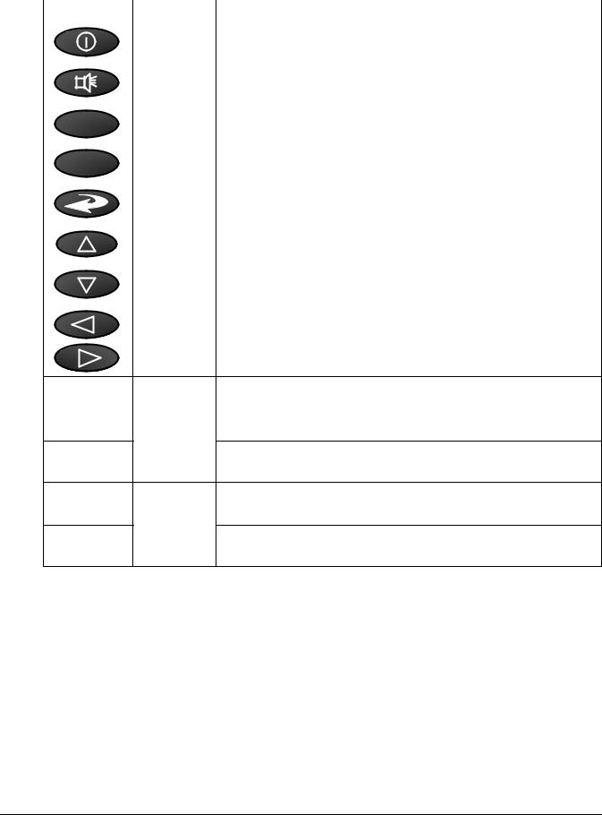
Table 1 |
Keyboard icons and functions |
|
|
|
|
|
|
Icon |
Key Name |
Function |
|
|
|
|
|
|
On/Off Key |
Controls the operational state of the cooling unit. |
|
|
|
|
|
|
Alarm Key |
Silences an alarm. |
|
|
|
|
? |
Help Key |
Accesses integrated help menus. |
|
|
|
||
|
|
|
|
|
ESC |
ESCape Key |
Returns to the previous display view. |
|
|
|
|
|
|
Enter Key |
Confirms all selections and selects icons or text. |
|
|
|
|
|
|
Increase Key |
Moves upward in a menu or increases the value of a selected parameter. |
|
|
(Up Arrow) |
|
|
|
|
|
|
|
|
|
|
|
Decrease Key |
Moves downward in a menu or reduces the value of a selected parameter. |
|
|
(Down Arrow) |
|
|
|
|
|
|
|
|
|
|
|
Left and Right |
Navigates through text and sections of the display. |
|
|
Arrow Keys |
|
|
|
|
|
Blinking Red—Active, unacknowledged alarm exists
Upper LED
Solid Red—Active, acknowledged alarm exists
Amber—Power is available to the unit, unit is NOT operating
Lower LED
Green—Power is available to the unit, unit is operating
3
Liebert iCOM Display Components and Functions
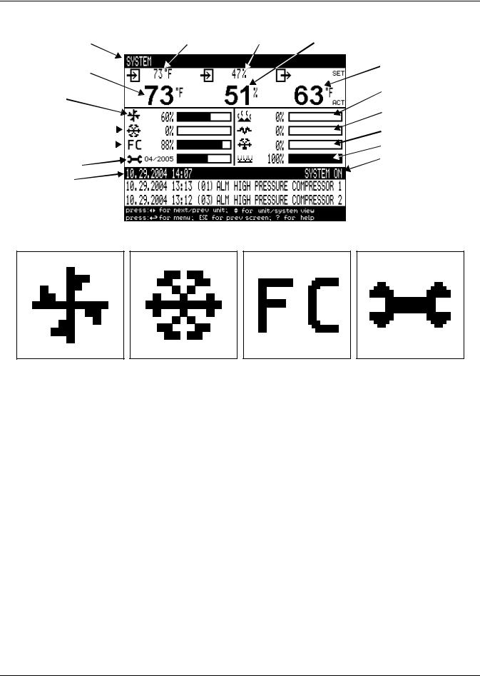
Figure 3 Status menu, large display, graphical view
|
|
|
|
Temperature |
Humidity |
Humidity |
|||
System or |
Setpoint |
Setpoint |
Sensor |
||||||
|
|
Reading |
|||||||
Unit # view |
|
|
|||||||
|
|
|
|
|
|
||||
Temperature Sensor |
|
|
|
|
|
Supply |
|||
|
|
|
|
|
Air Temperature |
||||
Reading |
|
|
|
|
|
||||
|
|
|
|
|
Percent Hot Water |
||||
|
|
|
|
|
|
|
|
|
|
Evaporator |
|
|
|
|
|
Heating |
|||
Fan Speed |
|
|
|
|
|
Percent Electric |
|||
|
|
|
|
|
|
|
|
|
Heating |
Percent Cooling |
|
|
|
|
|
|
|
Percent Dehumidifying |
|
|
|
|
|
|
|
|
|||
Free-Cooling |
|
|
|
|
|
|
|
Percent Humidifying |
|
Percentage |
|
|
|
|
|
||||
|
|
|
|
|
System (or Unit) On/Off |
||||
Next Maintenance |
|
|
|
|
|
||||
|
|
|
|
|
|
||||
Date and Time |
|
|
|
|
|
Most Recent Alarms |
|||
|
|
|
|
|
|||||
|
|
|
|
|
|
|
|
|
|
|
|
|
|
|
|
|
|
|
(Date, Time, Unit, |
|
|
|
|
|
|
|
|
|
Description) |
|
|
|
|
|
|
|
|
|
|
Figure 4 Liebert iCOM default screen symbols
fan |
cooling |
freecooling |
maintenance |
|
|
|
|
|
|
|
|
|
|
|
|
|
|
|
|
|
|
|
|
|
|
|
|
|
|
|
|
|
|
|
|
|
|
|
|
|
|
|
|
|
|
|
|
|
|
|
|
|
|
|
|
|
|
|
|
|
|
|
|
|
|
|
|
|
|
|
|
|
|
|
|
|
|
|
|
|
|
|
|
|
|
|
|
|
|
|
|
|
|
|
|
|
|
|
|
|
|
|
|
|
|
|
|
|
|
|
|
|
|
|
|
|
|
|
|
|
|
|
|
|
|
|
|
|
|
|
|
|
|
|
|
|
|
|
|
|
|
|
|
|
|
|
|
|
|
|
|
|
|
|
|
|
|
|
|
|
|
|
|
|
|
|
|
|
|
|
|
|
|
|
|
|
|
|
|
|
|
|
|
|
|
|
|
|
|
|
|
|
|
|
|
|
|
|
|
|
|
|
|
|
|
|
|
|
|
|
|
|
|
|
|
|
|
|
|
|
|
|
|
|
|
|
|
|
|
|
|
|
|
|
|
|
|
|
|
|
|
|
|
|
|
|
|
|
|
|
|
|
|
|
|
|
|
|
|
|
|
|
|
|
|
|
|
|
|
|
|
|
|
|
|
|
|
|
|
|
|
|
|
|
|
|
|
|
|
|
|
|
|
|
|
|
|
|
|
|
|
|
|
|
|
|
|
|
|
|
|
|
|
|
|
|
|
|
|
|
|
|
|
|
|
|
|
|
|
|
|
|
|
|
|
|
|
|
|
|
|
|
|
|
|
|
|
|
|
|
|
|
|
|
|
|
|
|
|
|
|
|
|
|
|
|
|
|
|
|
|
|
|
|
|
|
|
|
|
|
|
|
|
|
|
|
|
|
|
|
|
|
|
|
|
|
|
|
|
|
|
|
|
|
|
|
|
|
|
|
|
|
|
|
|
|
|
|
|
|
|
|
|
|
|
|
|
|
|
|
|
|
|
|
|
|
|
|
|
|
|
|
|
|
|
|
|
|
|
|
|
|
|
|
|
|
|
|
|
|
|
|
|
|
|
|
|
|
|
|
|
|
|
|
|
|
|
|
|
|
|
|
|
|
|
|
|
|
|
|
|
|
|
|
|
|
|
|
|
|
|
|
|
|
|
|
|
|
|
|
|
|
|
|
|
|
|
|
|
|
|
|
|
|
|
|
|
|
|
|
|
|
|
|
|
|
|
|
|
|
|
|
|
|
|
|
|
|
|
|
|
|
|
|
|
|
|
|
|
|
|
|
|
|
|
|
|
|
|
|
|
|
|
|
|
|
|
|
|
|
|
|
|
|
|
|
|
|
|
|
|
|
|
|
|
|
|
|
|
|
|
|
|
|
|
|
|
|
|
|
|
|
|
|
|
|
|
|
|
|
|
|
|
|
|
|
|
|
|
|
|
|
|
|
|
|
|
|
|
|
|
|
|
|
|
|
|
|
|
|
|
|
|
|
|
|
|
|
|
|
|
|
|
|
|
electric heat |
|
|
|
|
|
|
|
|
|
|
|
|
|
|
|
|
|
|
|
|
|
|
|
|
|
|
|
|
|
|
|
|
|
|
|
|
|||||||||||
|
|
|
|
|
|
|
|
|
|
|
|
|
|
|
|
|
|
|
|
|
|
|
|
|
|
|
|
|
|
|
|
|
|
|
|
|
|
|
|
|
|
|
|
|
|
|
|
|
|
|
|
|
|
|
|
|
|
|
||||||||||||
|
|
|
|
|
|
|
|
|
|
|
|
|
|
|
|
|
|
|
|
|
|
|
|
|
|
|
|
|
|
|
|
|
|
|
|
|
|
|
|
|
|
|
|
|
|
|
|
|
|
|
|
|
|
|
|
|
|
|
||||||||||||
|
|
|
|
hot water |
|
|
|
|
|
|
|
dehumidification |
|
|
humidification |
|||||||||||||||||||||||||||||||||||||||||||||||||||||||
4
Liebert iCOM Display Components and Functions
2.1Navigating Through the Liebert iCOM Menus
Liebert iCOM shows icons and text for monitoring and controlling your Liebert cooling units or network of cooling units. The number of icons and amount of text shown depends on the display size.
2.1.1Control Interface
When the buttons on the Liebert iCOM control have not been pressed for a short period, the display backlight turns off. Pressing any key will turn the backlight on (wake up the screen) and display the Status menu of the last cooling unit viewed. The Status menu will show the cooling unit’s operational mode(s), return air temperature and humidity readings, temperature and humidity setpoints and any active alarm conditions.
If the cooling unit has a large display and is not on a network, or if the unit has a small display, whether it is networked or stand-alone, the Status menu will display only that cooling unit’s information. Any large display that is connected to a network can be used to view any cooling unit on the network or show an average view of the entire system of cooling units.
The Liebert iCOM control has three main menus; User, Service and Advanced.
The User menu contains the most frequently used features, settings and status information. The Service menu contains settings and features used to set up unit communications and for unit maintenance. The Advanced menu contains settings used to set up the unit at the factory.
NOTE
Menu settings may be viewed without a password, but changing settings requires a password. If a password is required, Liebert iCOM shows a prompt to enter the password. The password for the User menu is 1490. The password for Service menu is 5010. For details on entering a password, see Entering a Password on page 6
2.1.2Accessing Submenus
To access the User, Service or Advanced menu, press the Enter or down arrow key while viewing the Status menu of the unit you wish to access. The User menu will be displayed first. To view the Service or Advanced menus, press the right arrow key.
Accessing Submenus on Small Displays
While viewing the menu you wish to access (User, Service or Advanced), use the up and down arrow keys to scroll through the icons page-by-page. To scroll through the icons one-by-one, press the enter key and then use the up and down arrow keys. With the desired icon highlighted, press the enter key to enter that submenu. Once in a Submenu, a list of parameters is displayed.
Press the enter key and use the up and down arrow keys to scroll through the parameters one-by-one. Pressing the Esc key will go back a level. Figure 5 shows the Liebert iCOM control menus for a small display.
Accessing Submenus on Large Displays
While viewing the menu you wish to access (User, Service or Advanced), press the enter key to highlight the first icon. Use the arrow keys to navigate through the icons. With the desired icon highlighted, press the enter key to enter that submenu. Once in a Submenu, a list of parameters will be displayed.
The up and down arrow keys may be used to scroll through the parameters page-by-page if the submenu has multiple pages. To scroll item-by-item, press the Enter key and then use the up and down arrow keys. Using the right or left arrow keys on large displays attached to a network will change the unit being viewed. Pressing the Esc key will go back a level. Figures 6 and 7 show the Liebert iCOM control menus for a stand-alone large display and for a networked large display, respectively.
NOTE
Settings are readable without a password, but changing settings requires a password.
5
Liebert iCOM Display Components and Functions
2.1.3Entering a Password
To change the value of a parameter in a menu, you must first enter the password for that menu. The User, Service and Advanced menus each has a unique password to prevent unauthorized changes.
The User menu password is 1490; the Service menu password is 5010.
NOTE
Entering the Service menu password permits access to both the User and Service menus.
To enter a password:
1.Navigate to the menu that contains the parameter to be changed.
2.Select Password in the submenu by pressing the Enter key
3.Press the Enter key to move your cursor to the right side of the screen to select the question marks.
4.Use the arrow keys to enter the numeral for the password’s first digit (the up arrow key moves from 1 to the next digit).
5.Use the right arrow key to move to the next question mark and repeat Step 4 to enter all digits in the password.
6.After entering the password, press enter.
If the password is correct, the Actual Level shown to the right of Password will change from 0 to 1 or 2. The menu will remain locked if the password was incorrect.
NOTE
Returning to the Status menu will require re-entering a password to make changes.
Figure 5 Menu tree—Small display, stand-alone or networked
Status Menu
Unit 1 View
|
|
|
|
|
|
|
|
|
|
|
|
|
|
|
|
|
|
|
|
|
|
|
|
|
User Menu |
|
Service Menu |
|
Advanced Menu |
|
|||||
|
Password |
|
Password |
|
|
Password |
|
||||
|
Setpoints |
|
Setpoints |
|
|
Factory Settings |
|
||||
|
Event Log |
|
Standby |
|
Access Passwords |
|
|||||
|
Graphics |
|
Wellness |
|
|
|
|
|
|||
|
|
|
|
|
|
|
|||||
|
Set Alarms |
|
Diagnostics |
|
|
|
|
|
|||
|
Sensor Data |
|
Set Alarms |
|
|
|
|
|
|||
|
Display Setup |
|
Calibration |
|
|
|
|
|
|||
|
Total Run Hours |
|
Network Setup |
|
|
|
|
|
|||
|
Sleep Mode |
|
Options Setup |
|
|
|
|
|
|||
|
Service Info |
|
Service Info |
|
|
|
|
|
|||
|
Active Alarms |
|
|
|
|
|
|
|
|
||
|
|
|
|
|
|
|
|
|
|
|
|
|
|
|
|
|
|
|
|
|
|
|
|
|
|
|
|
|
|
|
|
|
|
|
|
6

Liebert iCOM Display Components and Functions
Figure 6 Menu tree—Large display, stand-alone
Unit 1 will be displayed |
Status Menu – System View |
||||
in the top left corner of |
|||||
|
|
|
|
||
the screen. |
|
|
|
|
|
|
|
|
|
|
|
|
|
|
|
|
|
Status Menu
Unit 1 View
|
|
|
|
|
|
|
|
|
|
|
|
|
|
|
|
|
|
|
|
User Menu |
|
|
Service Menu |
|
Advanced Menu |
||||
Unit 1 |
|
|
Unit 1 |
|
Unit 1 |
||||
Password |
|
|
Password |
|
Password |
||||
Setpoints |
|
|
Setpoints |
|
Factory Settings |
||||
Spare Part List |
|
|
Unit Diary |
|
Compressor Info |
||||
Event Log |
|
Standby Settings/Lead-Lag |
|
Access Passwords |
|||||
Graphics |
|
Maintenance/Wellness Settings |
|
|
|
||||
View Network |
|
Diagnostics / Service Mode |
|
|
|
||||
|
|
|
|
||||||
Set Alarms |
|
|
Set Alarms |
|
|
|
|||
Sensor Data |
|
Sensor Calibration/Setup |
|
|
|
||||
Active Alarms |
|
|
System/Network Setup |
|
|
|
|||
Display Setup |
|
|
Options Setup |
|
|
|
|||
Total Run Hours |
|
|
Service Contact Info |
|
|
|
|||
Sleep Mode |
|
|
|
|
|
|
|
|
|
Service Contact Info |
|
|
|
|
|
|
|
|
|
|
|
|
|
|
|
|
|
||
|
|
|
|
|
|
|
|
|
|
7
Liebert iCOM Display Components and Functions
2.1.4Viewing Multiple Units with a Networked Large Display
When you first wake up the control, press the Esc key to return to the System view Status menu. This view shows an average of all the units on the network and any alarms present. To view a specific unit on the network, press either the enter key or down arrow key. When you do this, you will see the word System in the top left of the screen change to a unit number. Using the left and right arrow keys you can toggle through the various units on the network. To go back to the System view, or back one level from any menu in the control, press the Esc key.
Figure 7 Menu tree—Large display, networked
Unit # or System will be |
Status Menu – System View |
|
displayed in the top left |
||
(Networked Large Display Only) |
||
corner of the screen . |
||
|
||
|
|
Status Menu
Unit 1 View
Status Menu
Unit 2, 3, 4...
|
|
|
|
|
|
|
|
|
|
|
|
|
|
|
|
|
|
|
|
|
|
|
|
|
|
|
|
User Menu |
|
|
|
Service Menu |
|
|
Advanced Menu |
||||||
Unit # |
|
|
|
Unit # |
|
|
Unit # |
||||||
Password |
|
|
|
Password |
|
|
Password |
||||||
Setpoints |
|
|
|
Setpoints |
|
|
Factory Settings |
||||||
Spare Part List |
|
|
|
Unit Diary |
|
|
Compressor Info |
||||||
Event Log |
|
|
Standby Settings/Lead-Lag |
|
|
Access Passwords |
|||||||
Graphics |
|
|
Maintenance/Wellness Settings |
|
|
|
|
|
|||||
View Network |
|
|
Diagnostics / Service Mode |
|
|
|
|
|
|||||
|
|
|
|
|
|
|
|||||||
Set Alarms |
|
|
|
Set Alarms |
|
|
|
|
|
||||
Sensor Data |
|
|
Sensor Calibration/Setup |
|
|
|
|
|
|||||
Active Alarms |
|
|
System/Network Setup |
|
|
|
|
|
|||||
Display Setup |
|
|
|
Options Setup |
|
|
|
|
|
||||
Total Run Hours |
|
|
Service Contact Info |
|
|
|
|
|
|||||
Sleep Mode |
|
|
|
|
|
|
|
|
|
|
|
||
Service Contact Info |
|
|
|
|
|
|
|
|
|
|
|
||
|
|
|
|
|
|
|
|
|
|
|
|
|
|
8
Liebert iCOM Display Components and Functions
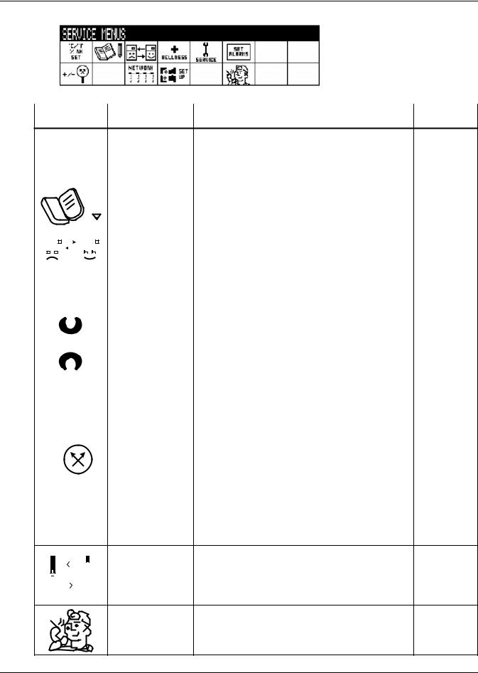
Figure 8 User menu icons
User Menu password: 1490
Table 2 User menu icons
Icon |
Name |
Description |
Available On Display |
°C / °F
% RH Setpoints View and change temperature and humidity Small & Large setpoints
SET
|
|
|
|
Spare Part List |
Displays the various part numbers of the |
Large |
|
|
|
|
|||
|
|
|
|
components/parts in the cooling unit |
||
|
|
|
|
|
|
|
|
|
|
|
|
|
|
|
|
|
|
|
|
|
|
|
|
|
|
|
|
|
|
|
|
|
|
|
|
|
|
|
|
||
|
EVENT |
Event Log |
Contains last 400 events |
Small & Large |
||
|
LOG |
|||||
|
|
|
|
|||
|
|
|
|
|
|
|
Graphics |
Displays temperature and humidity graphs |
Small & Large |
|
|
|
|
|
|
|
View Network |
Shows status of all connected units |
Large |
|
|
|
|
|
|
|
|||
|
|
|
|
|
|
|
|
|
|
|
|
|
SET |
Set Alarms |
Allows enable, disable and settings for alarms Small & Large |
|||||||
|
|
ALARMS |
||||||||||
|
|
|
|
|
||||||||
|
|
|
|
|
|
|
|
|
|
|
|
|
|
|
|
|
|
|
|
|
|
|
|
|
|
|
|
|
|
|
|
|
|
|
|
Sensor Data |
Shows readings of standard and optional |
Small & Large |
|
|
|
|
|
|
|
|
|
|
sensors |
||
|
|
|
|
|
|
|
|
|
|
|||
|
|
|
|
|
|
|
|
|
|
|
|
|
|
|
|
|
|
|
|
|
|
|
|
|
|
|
|
|
|
|
|
|
|
|
|
|
|
|
! |
|
|
|
|
|
Active Alarms |
Allows the user to view all current active |
Small & Large |
||||
|
|
|
|
|
|
|
|
|
|
alarms |
||
|
|
|
ACTIVE |
|
|
|||||||
|
|
|
|
|
|
|||||||
|
|
ALARMS |
|
|
|
|||||||
1 |
|
2 |
|
|
Change settings for display: language, time, |
|
||||||
|
|
|
|
|||||||||
9 |
|
|
|
|
|
|
3 Display Setup |
Small & Large |
||||
|
|
|
|
|
|
simple or graphic view |
||||||
|
|
|
|
|
|
|
|
|
|
|
|
|
SET 6
1234h |
Total Run Hours |
Records the run time of all components and |
Small & Large |
allows setting of limits on run time |
9
|
|
Liebert iCOM Display Components and Functions |
||
Table 2 |
User menu icons (continued) |
|
||
Icon |
Name |
Description |
Available On Display |
|
1 2 |
Allows setback settings for non-peak |
|
||
9 |
3 Sleep Mode |
Small & Large |
||
operation |
||||
|
6 |
|
||
|
|
|
||
|
Service Contact Info |
Contains key contact information for local |
Small & Large |
|
|
service, including names and phone numbers |
|||
10
Liebert iCOM Display Components and Functions
Figure 9 Service menu icons
Service Menu password: 5010
Table 3 |
Service menu icons |
|
|
|
|
|
Available On |
Icon |
Name |
Description |
Display |
|
|
|
|
|
|
°C / °F |
|
|
|
||||||||
|
|
|
|
|
|
|
% RH |
Setpoints |
To view and change temperature and humidity setpoints |
Small & large |
|||||||
|
|
|
|
|
|
|
|
|
SET |
|
|
|
|||||
|
|
|
|
|
|
|
|
|
|
|
|
|
|
|
|
|
|
|
|
|
|
|
|
|
|
|
|
|
|
|
|
|
Unit Diary |
Shows all entered program changes and maintenance |
Large |
|
|
|
|
|
|
|
|
|
|
|
|
|
|
|
|||
|
|
|
|
|
|
|
|
|
|
|
|
|
|
|
performed on the unit |
||
|
|
|
|
|
|
|
|
|
|
|
|
|
|
|
|||
|
|
|
|
|
|
|
|
|
|
|
|
|
|
|
|
|
|
|
|
|
|
|
|
|
|
|
|
|
|
|
|
|
|
|
|
|
|
|
|
|
|
|
|
|
|
|
|
|
|
|
Standby Settings/ |
Allows lead/lag setup when multiple units are connected |
Small & large |
|
|
|
|
|
|
|
|
|
|
|
|
|
|
|
|||
|
|
|
|
|
|
|
|
|
|
|
|
|
|
|
|||
|
|
|
|
|
|
|
|
|
|
|
|
|
|
|
|||
|
|
|
|
|
|
|
|
|
|
|
|
|
|
|
|||
|
|
|
|
|
|
|
|
|
|
|
|
|
|
|
Lead-Lag |
||
|
|
|
|
|
|
|
|
|
|
|
|
|
|
|
|||
|
|
|
|
|
|
|
|
|
|
|
|
|
|
|
|
|
|
|
|
|
|
|
|
|
|
|
|
|
|
|
|
|
|
|
|
|
|
|
|
|
|
|
|
|
|
|
|
|
|
|
|
|
|
|
|
|
|
|
|
|
|
|
|
|
|
|
|
|
Maintenance/ |
Allows setting maintenance interval reminder, |
|
|
|
|
|
|
|
|
|
|
|
|
|
|
|
|
|
||
|
|
|
|
|
|
|
|
|
|
|
|
|
|
|
|
||
|
|
|
|
|
|
|
|
|
|
|
|
|
|
|
|
||
|
|
|
|
|
|
|
|
|
|
|
|
|
|
|
maintenance message, number of unit starts and stops, |
Small & large |
|
|
|
|
|
|
|
|
|
|
|
|
|
|
|
|
Wellness Settings |
||
|
|
|
WELLNESS |
and time since last maintenance |
|
||||||||||||
|
|
|
|
|
|||||||||||||
|
|
|
|
|
|
||||||||||||
|
|
|
|
|
|
|
|
|
|
|
|
|
|
|
|
|
|
|
|
|
|
|
|
|
|
|
|
|
|
|
|
|
Diagnostics/ |
Allows troubleshooting, manual mode, read analog and |
Small & large |
|
|
|
|
|
|
|
|
|
|
|
|
|
|
|
|||
|
|
|
|
|
|
|
|
|
|
|
|
|
|
|
Service Mode |
digital inputs |
|
|
|
|
|
|
|
SERVICE |
|
||||||||||
|
|
|
|
|
|
|
|
|
|||||||||
|
|
|
|
|
|
|
|
|
|
|
|
|
|
|
|
|
|
|
|
|
|
|
|
|
|
|
SET |
Set Alarms |
Allows enable, disable and settings for alarms |
Small & large |
|||||
|
|
|
|
|
|
ALARMS |
|||||||||||
|
|
|
|
|
|
|
|
|
|||||||||
|
|
|
|
|
|
|
|
|
|
|
|
|
|
|
|
|
|
|
|
|
|
|
|
|
|
|
|
|
|
|
|
|
|
|
|
+ / - |
|
|
|
|
|
Sensor |
Allows calibration of sensors |
Small & large |
|||||||||
|
|
|
|
|
Calibration/Setup |
||||||||||||
|
|
|
|
|
|||||||||||||
|
|
|
|
|
|
|
|
|
|
|
|
|
|
|
|
|
|
|
|
|
|
|
|
|
|
|
|
|
|
|
|
|
|
|
|
NETWORK |
System/Network |
|
|
||||||||||||||
|
|
|
|
|
|
|
|
|
|
|
|
|
|
|
Allows setup and U2U communication for multiple units |
Large |
|
|
|
|
|
|
|
|
|
|
|
|
|
|
|
|
|||
|
|
|
|
|
|
|
|
|
|
|
|
|
|
|
Setup |
||
|
|
|
|
|
|
|
|
|
|
|
|
|
|
|
|||
|
|
|
|
|
|
|
|
|
|
|
|
|
|
|
|
|
|
|
|
|
|
|
|
|
|
|
|
|
|
|
|
|
|
|
|
|
|
|
|
|
|
|
|
|
|
|
|
|
|
|
|
|
|
|
|
|
|
|
|
|
|
Options Setup |
Allows setup of component operation |
Small & large |
|
|
|
|
|
|
|
|
|||
|
|
|
|
|
|
|
|
|||
|
|
|
|
|
|
|
|
|||
|
|
|
|
|
|
|
|
|||
|
|
|||||||||
|
|
|
|
|
|
|
|
|
|
|
|
|
|
|
|
|
|
|
|
|
|
|
|
|
|
|
|
|
|
|
|
|
Service Contact Info |
Contains key contact information for local service, |
Small & large |
including names and phone numbers |
11

Operation
3.0OPERATION
The Liebert iCOM display for your Liebert cooling unit features an easy-to-use, menu-driven liquid crystal display (LCD). All unit settings and parameters can be viewed and adjusted through three menus: User, Service and Advanced. All active alarms are displayed on the LCD and annunciated.
The control is shipped from the factory with default selections for all necessary settings. Adjustments can be made if the defaults do not meet your requirements.
References to menu items in this manual are followed by the main menu and the submenu where they can be found.
For example:
•Temperature Setpoint (User Menu, Setpoints) - The Temperature Setpoint parameter is located in the User menu under the Setpoints submenu.
•High Return Humidity (Service Menu, Set Alarms) - The High Return Humidity alarm is located in the Service menu under the Set Alarms submenu.
3.1Single Unit Functions
3.1.1Unit/Fan Control Start - Stop
Unit on means the fan output is activated. The unit can be switched On and Off from two inputs:
1.Remote on/off input
2.Display button
Pressing the On/Off key on a small display will control only the cooling unit it is connected to regardless, of whether the cooling unit is a stand-alone unit or part of a network.
Pressing the On/Off key on a large display of a stand-alone cooling unit will control only that unit.
The effect of pressing the On/Off key on a large display connected to a network depends on the view: System or Unit.
•In System view, pressing the On/Off key shows a warning asking for confirmation to shut down the entire system.
•In Unit view, pressing the On/Off key affects only the unit being viewed, without a confirmation request.
Each time a unit is powered on or off, an event is added to the Event Log in the User menu.
NOTE
Customer switches: remote On/Off (if used) and display On/Off switches are in series. A cooling unit will start only if both switches are On; if one of these switches is Off, the unit will stop. Safety devices within the unit are also in series and will shut the unit down if required.
Figure 10 Start-stop priority switches
|
|
Remote On / Off |
Display On / Off |
|
||||||||
|
|
|
|
|
|
|
|
|
|
|
|
|
|
|
|
|
|
|
|
|
|
|
|
|
|
NOTE
If Remote On/Off is not used, a jumper is inserted to bypass the switch.
12

Operation
Autorestart
When there is a loss of power to the cooling unit and power comes back, the unit will return to its previous operating status—on if it was on before the power off, off if it was off.
When power returns, the autorestart time—time-selectable: Single Unit Auto Restart (Service Menu, Options Setup)—controls the start of the unit. The autorestart time runs in a loop, starting the next unit each time when elapsed, starting with Unit # 1.
Loss of Power Alarm
A Loss of Power Alarm is activated when power is restored after an interruption. If acknowledged, the alarm resets automatically after 30 minutes. This alarm can be set to different event types (Message, Alarm or Warning) and can be disabled under menu item Loss of Power (Service Menu, Set Alarms).
NOTE
Loss of power alarm will be activated only on units that had the fan on before power was lost.
Fan Alarm / Fan Protection Settings
The fan operation is protected by two digital devices: motor protection (optional) and a differential pressure switch. The motor protection monitors for main fan overload and the differential pressure switch ensures that the blower(s) are moving air. If either protection device triggers, an alarm will be announced by a buzzer, alarm relay and event to monitoring after an adjustable time-delay (Main Fan Overload and Loss Of Airflow in Service Menu, Set Alarms).
The time delay at the unit start is always five seconds shorter than the control delay (to avoid short component starting when the fan is not working). During operation, the fan delay is fixed to
15 seconds.
There are two selection possibilities for both, Loss Of Airflow and Main Fan Overload:
•Shutdown—stops the unit (intended for DX models).
•Disable—stops the humidifier, electrical heaters and dehumidification; allows cooling and free-cooling only (intended for chilled water models / external cooling).
NOTE
When the Main Fan Overload alarm is active, the Loss of Airflow alarm is masked out.
3.1.2Chilled Water Units with Variable Speed Motor
VSD Fan Speed (Auto or Manual VSD Fan Speed Control)
The parameter VSD Fan Speed (Service Menu, Setpoints) allows the cooling unit's fan motor speed to be set for:
•Auto operation: when set to Auto, the speed of the VSD (variable speed drive) motor follows the position of the chilled water valve based on predetermined logic for cooling and dehumidification operation.
•Manual operation: when set to Manual, the speed of the VSD motor follows user input as set
either locally at the cooling unit's Liebert iCOM display (under VSD Setpoint in Service Menu, Setpoints) or remotely using Modbus BMS signal with an optional Liebert IntelliSlot® 485 card.
VSD Setpoint (VSD Fan Speed Setting)
If the VSD Fan Speed Control (Service Menu, Setpoints) is set for Manual, the VSD Fan Speed Setpoint (Service Menu, Setpoints) may be set for the desired speed of the variable speed motor.
Depending on the product control design, there may be an internal minimum speed, as defined by that specific product operation, while the customer input may be set for 0-100%:
•Fan speed may be set locally at the unit using the Liebert iCOM display.
•Fan speed may be set remotely via a BMS signal (sent via Modbus using an optional Liebert IntelliSlot 485 card), which then transmits to the unit local control.
13

Operation
3.1.3General Compressor Requirements Low-Pressure Time Delay
When the compressor starts, the low-pressure input is ignored for a selected period of time based on the setting of the Low Pressure Alarm Delay (Service Menu, Options Setup). This time is usually set to 3 minutes on air-cooled units, and to 0 or 1 minute on water cooled units. When this time is expired, a second timer starts to operate if the low-pressure input is active. This second timer is active during normal compressor operation to avoid compressor trips due to bubbles in the refrigerant or other influences creating short trips of the low-pressure switch. The low-pressure switch input is enabled only if the compressor is operating. Exception: Pump Down (see Pump Down).
NOTE
Low-pressure condition could be read through contacts or through pressure transducers with threshold setting.
Pump Down
The Pump Down operation is performed to protect the compressor oil from being diluted with liquid refrigerant to ensure that the compressor is properly lubricated for the next startup. The Pump Down operation operates in the following manner:
Whenever a compressor is turned Off and the low-pressure switch is closed (pressure OK), the compressor will be operated with the LLSV (liquid line solenoid valve) closed (de-energized) until the lowpressure switch opens (low-pressure condition, without giving alarm). When there is a call to turn off a compressor the LLSV is closed. If the low suction pressure switch (LPS) does not open within a specified time, the LLSV is turned On then back Off (to try to unstick the LLSV). The control will then wait a set period of time for the LPS to open. This will happen three times. If, after three times, the low suction pressure switch does not open, the compressor and LLSV are locked off and an alarm “Pump Down not completed” will appear.
There is a re-pump down if the LPS opens again after the compressor has been already stopped—a maximum of six re-pump-down cycles per hour are allowed. At the seventh request of re-pump down the alarm “Comp 1 Pumpdown Fail” or “Comp 2 Pumpdown Fail” will appear and the compressor will be locked out.
Pump down is always performed loaded (for compressors with unloaders: unloaders off, digital scroll: control solenoid valve disabled).
For digital scroll only: when pump down has finished successfully (LPS opened), pump down will be continued for another half-second with the control solenoid valve energized.
High Pressure Alarm
When the compressor is initially activated, the system will be monitored for a high pressure situation. When a high pressure situation is detected during the first 10 minutes of operation, the unit will attempt to correct the problem several times without notification. If the unit is unsuccessful in correcting the problem, an alarm will occur and the affected compressor will be locked off. If high head pressure alarm trips three times in a rolling 12 hour period, the affected compressor will be locked off.
After the compressor has been running for 10 minutes, if a high head pressure situation is detected, an alarm will occur and the affected compressor will be immediately locked off without the unit trying to correct the problem.
Once the compressor is locked off, it will not come back on until main power is reset, or until the
HP Alarm Counters (Service Menu, Diagnostics) are reset to 0. Setting the counter to 0 will auto-reset the alarm without the need of pressing the reset button on the display. Even if the pressure in the system drops below the alarm point, the compressor will remain off until the system is reset.
NOTE
If the unit is equipped with manual reset high head pressure switches, or if the auto reset high head pressure switches don’t reset, the compressor will not be turned back on, but there will be a 30-second delay from when the high head pressure situation occurs and when the alarm is annunciated.
14
Operation
Digital Scroll High Temperature
A protective maximum operating compressor temperature limit is imposed on units with digital scroll compressor(s) with thermistor. Once the digital scroll temperature reaches the maximum temperature threshold, the compressor will be locked out for at least 30 minutes and an alarm will be annunciated. If after 30 minutes the temperature has cooled to a safe operating temperature, the compressor will resume operation.
Each time a high-temperature alarm occurs, HT 1 Alarm Counter (Service Menu, Diagnostics) or HT 2 Alarm Counter (Service Menu, Diagnostics) is increased by one. Once these counters reach five occurrences in a rolling four-hour period, the compressor will be locked out. The alarm can be reset once the temperature returns to a safe level by:
1.Setting the counter back to 0 from the display and pressing the alarm reset button.
2.Shutting off power to the control board by turning the cooling unit's main power disconnect switch Off and On.
3.1.4Compressor Timing—Units With Two Compressors
To help maximize the life of your compressor(s), there is a start-to-next start delay for each single compressor.
A Minimum ON time and a Minimum Off time may be selected in the Advanced menu (minimum three minutes for single phase compressors). Consult the factory on how to modify the Minimum ON and OFF time settings.
3.1.5Compressor Sequencing
Compressor Sequencing parameter (Service Menu, Options Setup) is intended to maintain equal run times between compressors. This setting has three selection possibilities:
•Always use Compressor 1 as lead compressor
•Always use Compressor 2 as lead compressor
•Auto:
•First priority: if the safety timings are acceptable for only one compressor, then it is the next to be started/stopped.
•If both compressors are off: the one with fewer working hours is the next to start.
•If both compressors are in operation: the one that has been operating longer since the last start is the next to be stopped.
NOTE
The Auto setting attempts to maintain equal run times between compressors.
15

Operation
3.2Motorized Ball Valve in Digital Scroll Units
On digital scroll units, discharge pressure is controlled by a motorized ball valve. During unloaded operation, pressure changes during each digital cycle could cause a pressure-controlled water regulating valve to open and close an excessive number of times.
The motorized ball valve is designed to maintain a consistent peak discharge pressure on Water/Glycol Cooled Digital Compressor Systems.
The control algorithm for the motorized ball valve uses an intelligent sampling rate and adjustable pressure thresholds to reduce the number of times the valve opens and closes. The valve assembly consists of the brass valve, linkage and actuator.
Each compressor has one motorized ball valve that is driven by the analog output of the Liebert iCOM control board based on pressure. If there is a call for cooling, the compressor start is delayed by a 30second timer. During this delay, the motorized ball valve is set to 50% open. The compressor will start after the 30-second timer elapses.
Motorized Ball Valve Manual Mode: (Service/Service) Manual operation can be selected to allow service personnel to control the motorized ball valve from the Liebert iCOM control only when the system is in manual mode.
When Auto BV Control is selected, the motorized ball valve functions as it would be during normal system operation.
NOTE
Compressor operation will be delayed 30 seconds to allow the motorized ball valve to position itself for initial startup.
When Manual BV Control is selected, the user must be careful in setting the analog output because the ball valves will remain in the position set in the Service menu until the control is switched back to Auto or until a technician changes the valves to another manual position (the motorized ball valve in manual mode can be set in 1% increments from fully closed to fully open). Lowor high-discharge pressure may occur during this mode, depending on environmental conditions and the position of the motorized ball valve.
The motorized ball valve is driven by a 2-10VDC proportional control signal: the valve is closed at 2VDC, 50% open at 6VDC and fully open at 10 VDC.
3.2.1MBV Operation After Compressor is Turned Off
Once a compressor has stopped, the MBV control will continue to change the MBV position to maintain system pressures for a maximum time of 10 minutes by following the auto control algorythm. When the 10-minute delay has expired or the discharge pressure is below its minimum threshold the motorized ball valve will close until the next compressor activation.
3.2.2Service Offset—Changing System Pressure Settings
The MBV control is set to maintain a system pressure specific to the particular type of cooling unit. A properly trained and qualified technician can increase or decrease the pressure through the Ball Valve Setpoint Offset found in the Service/Options Setup menu. The range is 0 to 50 PSI; the default is 30 PSI.
NOTE
Adjusting this parameter will increase or decrease the operating compressor discharge pressure by changing the targeted range of control. The discharge pressure is the peak pressure of the digital cycle.
16
Operation
3.3Temperature Control—Single Source Cooling (No Extra Cooling Coil)
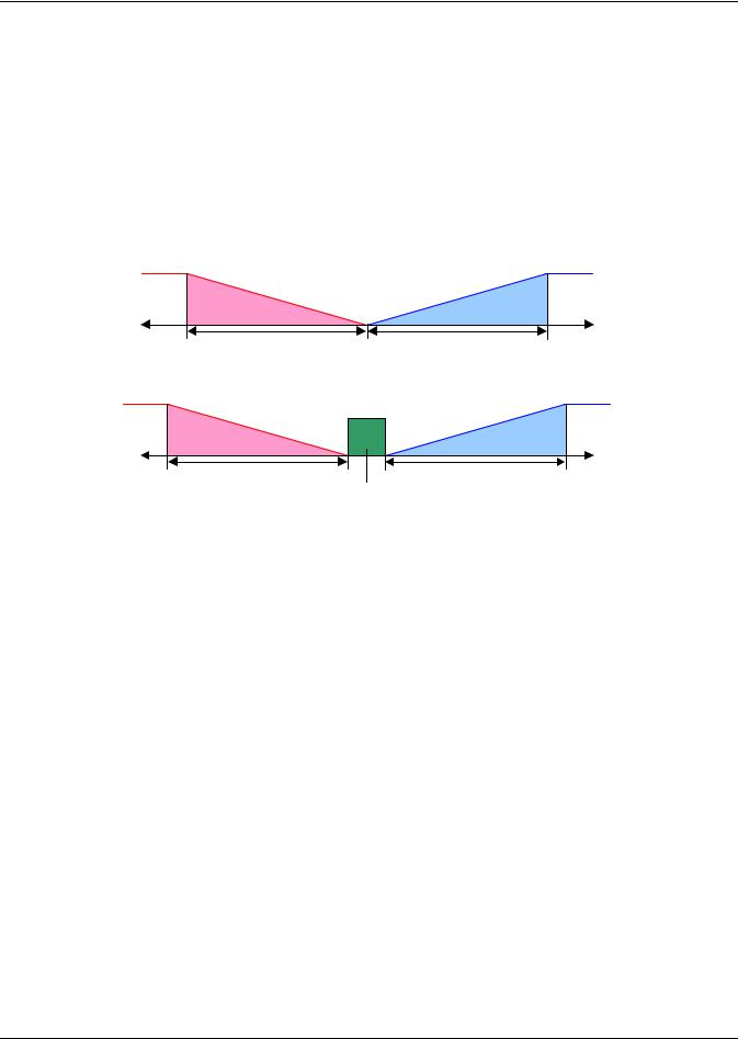
3.3.1Temperature Proportional Band
The control uses the temperature proportional band to determine which operation to perform (cooling/heating) and how intensely to perform it. The Temperature Proportional Band is a user-defined range that is divided into two equal parts for cooling and heating. The Temperature Setpoint is between these two equal parts.
An optional Temperature Deadband range can be defined, which is equally divided on either side of the setpoint and separates the two halves of the proportional band. Figure 11 illustrates how the temperature proportional band is evenly divided on either side of the temperature setpoint, with and without a deadband.
Figure 11 Temperature proportional band
|
|
Without Deadband |
|
||
- Temp |
Heating |
|
Cooling |
+ Temp |
|
|
½ Proportional Band |
|
½ Proportional Band + 100% |
||
|
- 100% |
0% |
|
||
|
Heating |
|
Setpoint |
Cooling |
|
With Deadband
|
|
Dead- |
|
|
|
- Temp |
Heating |
band |
Cooling |
+ Temp |
|
- 100% ½ Proportional Band |
|
|
½ Proportional Band + 100% |
||
|
0% |
0% |
|
||
|
Heating |
Setpoint |
Cooling |
|
|
When the return air temperature deviates from the setpoint it begins to penetrate one of the proportional band halves, cooling or heating. If the return air temperature increases, the control calls for 0% (none) to 100% (full) cooling capacity based on how far the temperature penetrates the cooling portion of the proportional band. If the return air temperature decreases, the control calls for 0% (none) to - 100% (full) heating capacity based on how far the temperature penetrates the heating portion of the proportional band.
When the return air temperature reaches the end of the proportional band, either 100% or -100%, full cooling or full heating capacity is provided. No operation is performed when a 0% call is calculated. The control varies the call for cooling and heating in 1% increments as the return air temperature moves through the proportional band halves.
The deadband range is used to widen the setpoint. When the return air temperature falls within the deadband, the control operates the same as if the temperature equaled the setpoint exactly. This setting helps maximize component life by preventing excessive component cycling. The Temperature Proportional Band and Temperature Deadband parameters are in the Service menu under the Setpoints submenu. The Temperature Setpoint parameter is in both the User Menu and Service Menu under Setpoints.
There is a parameter AutoSet Enable (Service Menu, Setpoints), which automatically sets the proportional bands for temperature and humidity, and both the integration time factors according to the type of unit (Chilled Water, single or double compressor), with influence of the selected Teamwork Mode. See 4.1 - Teamwork Modes for more on using this feature.
17
Operation
3.3.2Compressor Control
Depending on the type of Liebert air conditioning unit you have your unit may contain one or two compressors with or without unloaders.
Compressor Proportional Bands
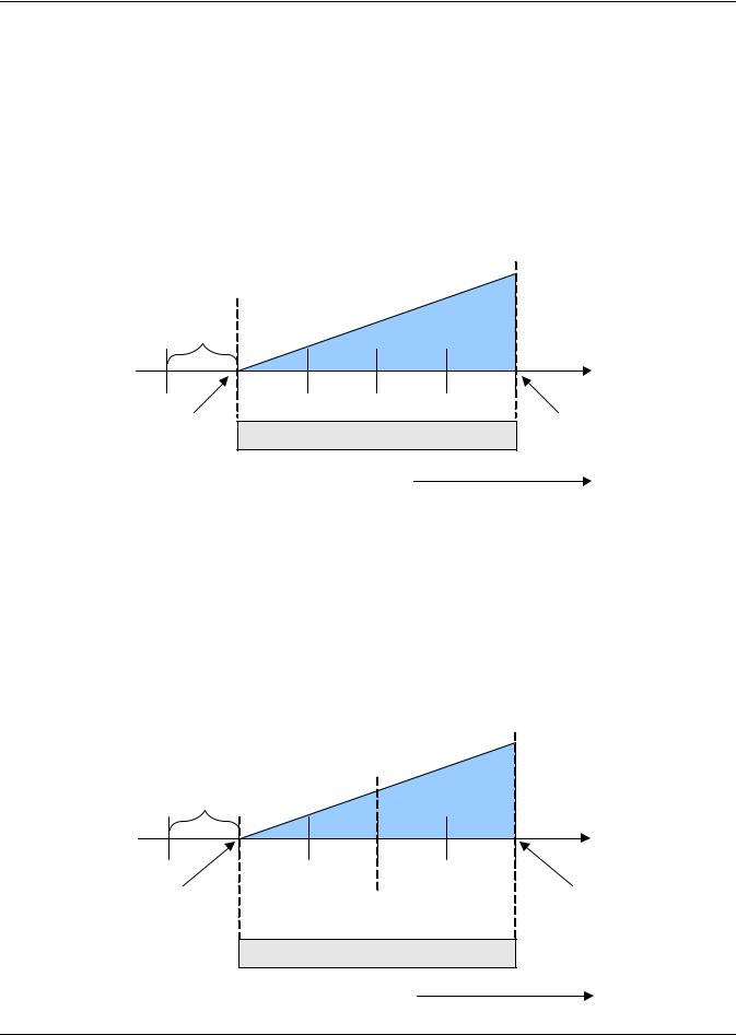
One Single-Step Compressor Without Unloaders—One-Step
One single-step compressor, Cool 1, is started at 100% call for cooling from the temperature proportional band and stopped at 0% (see Figure 12).
Figure 12 One single-step compressor without unloaders
Temp Setpoint: 70°F |
|
Proportional Band : 8°F |
Cool 1 |
Deadband : 2°F |
On |
Cool 1 |
|
Off |
|
½ Dead- |
|
band |
|
70 |
71 |
72 |
73 |
74 |
75 |
0% |
|
½ |
Proportional Band |
+ 100% |
|
Cooling |
|
Cooling |
|||
|
|
|
|
||
Increasing Temperature
Two Single-Step Compressors Without Unloaders—Two-Step
First single-step compressor, Cool 1, is started at 50% calculated output from the temperature proportional band, and stopped at 0%. The second compressor, Cool 2, starts at 100% and stops at 50% (see
Figure 13).
One Compressor With an Unloader—Two-Step
The two-step compressor is started unloaded at 50%, Cool 1, calculated output from the temperature proportional band and stopped at 0%. At 100% the compressor starts fully loaded, Cool 2, and returns to unload operation at 50% (see Figure 13).
Figure 13 Two single-step compressors without unloaders or one compressor with an unloader (two-step)
Temp Setpoint: 70°F Proportional Band: 8°F Deadband : 2°F
1/2 Dead-
band
Cool 1
On
Cool 2
On
70 |
71 |
72 |
73 |
74 |
75 |
0% |
Cool 1 |
|
Cool 2 |
|
+ 100% |
Cooling |
Off |
|
Off |
|
Cooling |
1/2 Proportional Band
Increasing Temperature
18
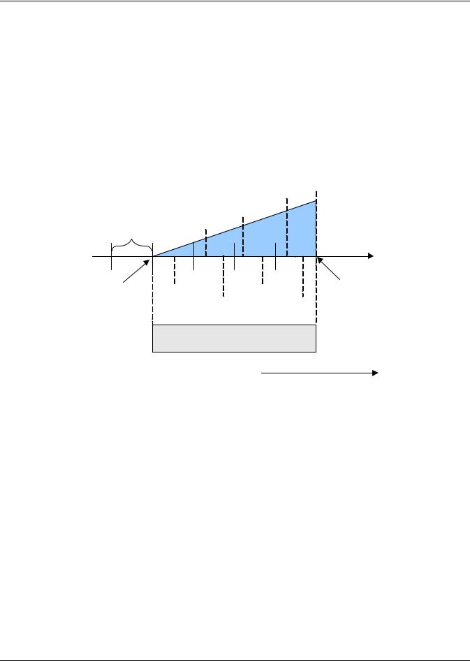
Operation
Two Compressors With Unloaders—Four-Step
The first two-step compressor is started unloaded at 33% calculated output from the temperature proportional band and stopped at 17%. At 80% Compressor 1 will be loaded, at 70% unloaded.
The second compressor starts unloaded at 63% and stops at 47%. At 100%, Compressor 2 will be loaded, at 90% unloaded (see Figure 14).
The four stages of cooling are accomplished in the following manner:
•1 stage: One compressor, unloaded - Cool 1
•2 stages: Both compressors, unloaded - Cool 2
•3 stages: One compressor, loaded and one compressor, unloaded - Cool 3
• 4 stages: Both compressors, loaded - Cool 4
Figure 14 Two compressors with unloaders (four-step)
Temp Setpoint: 70°F Proportional Band: 8°F Deadband : 2°F
Cool 1 ½ DeadOn
band
Cool 4
Cool 3 On
On
70 |
71 |
72 |
73 |
74 |
75 |
+ 100% |
0% |
|
Cool 1 |
|
Cool 3 |
|
|
|
|
|
Cooling |
|||
Cooling |
|
Off |
Cool 2 |
Off |
Cool 4 |
|
|
|
|||||
|
|
|
Off |
|
Off |
|
½ Proportional Band
Increasing Temperature
19
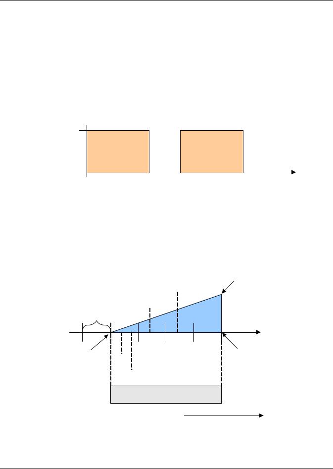
Operation
Digital Scroll Compressors
A compressor with a suction cutoff unloader can only modulate its capacity between two distinct levels: fully loaded and half loaded. A digital scroll compressor can modulate its capacity anywhere between 10-100%. This variable capacity modulation allows cooling units to control an environment more precisely.
Digital scroll capacity modulation is achieved by energizing and de-energizing a solenoid valve on the compressor. When the solenoid valve is de-energized, the compressor capacity is 100%. When the solenoid valve is energized, the compressor capacity is zero. Therefore, the capacity of the compressor depends on how long the solenoid is de-energized for. If the solenoid is de-energized for 10-seconds, then energized for 5 seconds during a 15-second cycle, the resulting capacity will be 66% as shown in
Figure 15.
Figure 15 Digital scroll capacity modulation, 10-100% variable
Call for Cooling: 66% 100% Loaded
|
|
|
Solenoid |
|
Solenoid |
Solenoid |
|
|
Solenoid |
|||||
|
|
|
De-energized |
|
Energized |
De-energized |
|
|
Energized |
|||||
0% Loaded |
|
|
|
|
|
|
|
|
|
|
|
|
|
|
|
|
|
|
|
|
|
|
|
|
|
|
|
|
|
|
|
|
|
|
|
|
|
|
|
|
|
|
|
|
0 |
5 |
10 |
15 |
20 |
25 |
30 |
||||||||
|
|
|
|
|
|
|
||||||||
|
|
|
15-Second Capacity |
|
|
15-Second Capacity |
|
|||||||
|
|
|
Modulation Cycle |
|
|
Modulation Cycle |
|
|||||||
|
|
|
|
|
|
|
|
|
|
|
|
|
|
|
On single and dual digital scroll compressor systems, the first compressor is started at 25% calculated output from the temperature proportional band and stopped at 10%. On dual digital scroll compressor systems, the second compressor is started at 35% and stopped at 20%, see Figure 16. When a compressor is started, the solenoid is energized longer than it is de-energized to match the call for cooling. When the call for cooling increases to 100%, the solenoid is de-energized for the entire 15 second cycle.
Figure 16 Single and dual digital scroll compressor activation points
Temp Setpoint: 70°F |
|
Proportional Band : 8°F |
Comp 2 On Partially |
Deadband : 2°F |
Loaded |
Comp 1 On Partially
Loaded
½ Dead-
band
Comp 1 & 2 On
Fully Loaded
70 |
71 |
72 |
73 |
74 |
75 |
0% |
Comp 1 |
|
|
|
+ 100% |
|
|
|
Cooling |
||
Cooling |
Off |
|
|
|
|
|
|
|
|
Comp 2
Off
½ Proportional Band
Increasing Temperature
20
Loading...