


 Loading...
POWER AVAILABILITY
GXT5000R-208
with GXT5VBATTW120 / GXT5VBATT Battery Cabinets |
USER MANUAL |
|
5000VA/3750W
208Volt

TABLE OF CONTENTS
IMPORTANT SAFETY INSTRUCTIONS . . . . . . . . . . . . . . . . . . . . . . . . . . . . . . . . . . . . . . . . . . 1 GLOSSARY OF SYMBOLS . . . . . . . . . . . . . . . . . . . . . . . . . . . . . . . . . . . . . . . . . . . . . . . . . . 3 INTRODUCTION AND SYSTEM DESCRIPTION . . . . . . . . . . . . . . . . . . . . . . . . . . . . . . . . . . . . . 4 MAJOR COMPONENTS . . . . . . . . . . . . . . . . . . . . . . . . . . . . . . . . . . . . . . . . . . . . . . . . . . . . 5
Transient Voltage Surge Suppression (TVSS) & EMI/RFI Filters . . . . . . . . . . . . . . . . . . . 5 Rectifier/Power Factor Correction (PFC) Circuit. . . . . . . . . . . . . . . . . . . . . . . . . . . . . . . . 5 Inverter . . . . . . . . . . . . . . . . . . . . . . . . . . . . . . . . . . . . . . . . . . . . . . . . . . . . . . . . . . . . . . . . . 5 Battery Charger . . . . . . . . . . . . . . . . . . . . . . . . . . . . . . . . . . . . . . . . . . . . . . . . . . . . . . . . . . 5 DC to DC Converter . . . . . . . . . . . . . . . . . . . . . . . . . . . . . . . . . . . . . . . . . . . . . . . . . . . . . . . 5 Battery. . . . . . . . . . . . . . . . . . . . . . . . . . . . . . . . . . . . . . . . . . . . . . . . . . . . . . . . . . . . . . . . . . 5 Auxiliary 120V / 400VA Power . . . . . . . . . . . . . . . . . . . . . . . . . . . . . . . . . . . . . . . . . . . . . . 6 Dynamic Bypass . . . . . . . . . . . . . . . . . . . . . . . . . . . . . . . . . . . . . . . . . . . . . . . . . . . . . . . . . 6
GENERAL DESCRIPTION . . . . . . . . . . . . . . . . . . . . . . . . . . . . . . . . . . . . . . . . . . . . . . . . . . . 7 GENERAL INSTALLATION . . . . . . . . . . . . . . . . . . . . . . . . . . . . . . . . . . . . . . . . . . . . . . . . . . 9 CONTROLS AND INDICATORS . . . . . . . . . . . . . . . . . . . . . . . . . . . . . . . . . . . . . . . . . . . . . . 10 MODES OF OPERATION . . . . . . . . . . . . . . . . . . . . . . . . . . . . . . . . . . . . . . . . . . . . . . . . . . 12
Normal Mode Operation . . . . . . . . . . . . . . . . . . . . . . . . . . . . . . . . . . . . . . . . . . . . . . . . . . 12 Battery Mode Operation . . . . . . . . . . . . . . . . . . . . . . . . . . . . . . . . . . . . . . . . . . . . . . . . . . 12 Bypass Mode . . . . . . . . . . . . . . . . . . . . . . . . . . . . . . . . . . . . . . . . . . . . . . . . . . . . . . . . . . . 13 Battery Recharge Mode. . . . . . . . . . . . . . . . . . . . . . . . . . . . . . . . . . . . . . . . . . . . . . . . . . . 13
OPERATING INSTRUCTIONS . . . . . . . . . . . . . . . . . . . . . . . . . . . . . . . . . . . . . . . . . . . . . . . 14
Turn On . . . . . . . . . . . . . . . . . . . . . . . . . . . . . . . . . . . . . . . . . . . . . . . . . . . . . . . . . . . . . . . . 14 Manual Bypass. . . . . . . . . . . . . . . . . . . . . . . . . . . . . . . . . . . . . . . . . . . . . . . . . . . . . . . . . . 14 Standby . . . . . . . . . . . . . . . . . . . . . . . . . . . . . . . . . . . . . . . . . . . . . . . . . . . . . . . . . . . . . . . . 14
OPTIONAL BATTERIES - PROGRAMMABLE RUN TIME. . . . . . . . . . . . . . . . . . . . . . . . . . . . . 15
Programming the GXT5000R-208 for Battery Cabinet Count . . . . . . . . . . . . . . . . . . . . 15 Procedure to confirm the battery count . . . . . . . . . . . . . . . . . . . . . . . . . . . . . . . . . . . . . 16 Procedure to change the battery count . . . . . . . . . . . . . . . . . . . . . . . . . . . . . . . . . . . . . . 16
COMMUNICATIONS . . . . . . . . . . . . . . . . . . . . . . . . . . . . . . . . . . . . . . . . . . . . . . . . . . . . . . 17
Relay Interface Card . . . . . . . . . . . . . . . . . . . . . . . . . . . . . . . . . . . . . . . . . . . . . . . . . . . . . 17 Pin Configuration . . . . . . . . . . . . . . . . . . . . . . . . . . . . . . . . . . . . . . . . . . . . . . . . . . . . . . . 17 EPO . . . . . . . . . . . . . . . . . . . . . . . . . . . . . . . . . . . . . . . . . . . . . . . . . . . . . . . . . . . . . . . . . . . 18
SERIAL COMMUNICATIONS . . . . . . . . . . . . . . . . . . . . . . . . . . . . . . . . . . . . . . . . . . . . . . . . 19
Serial Cable . . . . . . . . . . . . . . . . . . . . . . . . . . . . . . . . . . . . . . . . . . . . . . . . . . . . . . . . . . . . 19
i

UPS COMMUNICATIONS WITH INTELLISLOT . . . . . . . . . . . . . . . . . . . . . . . . . . . . . . . . . . . . 20
MAINTENANCE . . . . . . . . . . . . . . . . . . . . . . . . . . . . . . . . . . . . . . . . . . . . . . . . . . . . . . . . . 21
TROUBLESHOOTING . . . . . . . . . . . . . . . . . . . . . . . . . . . . . . . . . . . . . . . . . . . . . . . . . . . . . 22
SPECIFICATIONS . . . . . . . . . . . . . . . . . . . . . . . . . . . . . . . . . . . . . . . . . . . . . . . . . . . . . . . 24
BATTERY CABINET SPECIFICATIONS . . . . . . . . . . . . . . . . . . . . . . . . . . . . . . . . . . . . . . . . . 25
FIGURES
Figure 1 GXT5000R-208 UPS - Front view . . . . . . . . . . . . . . . . . . . . . . . . . . . . . . . . . . . . . . . . . . . . . 7 Figure 2 GXT5000R-208 UPS - Rear view . . . . . . . . . . . . . . . . . . . . . . . . . . . . . . . . . . . . . . . . . . . . . 7 Figure 3 GXT5VBATTW120 battery cabinet with auxiliary 120 VAC power - Rear view . . . . . . . . 8 Figure 4 GXT5VBATT battery cabinet - Rear view. . . . . . . . . . . . . . . . . . . . . . . . . . . . . . . . . . . . . . . 8
TABLES
Table 1 Pin configuration . . . . . . . . . . . . . . . . . . . . . . . . . . . . . . . . . . . . . . . . . . . . . . . . . . . . . . . . . 17 Table 2 LED indicators . . . . . . . . . . . . . . . . . . . . . . . . . . . . . . . . . . . . . . . . . . . . . . . . . . . . . . . . . . . 22 Table 3 Troubleshooting guide . . . . . . . . . . . . . . . . . . . . . . . . . . . . . . . . . . . . . . . . . . . . . . . . . . . . . 23
ii

IMPORTANT SAFETY INSTRUCTIONS
!WARNING
OPENING OR REMOVING THE COVER MAY EXPOSE YOU TO LETHAL VOLTAGES WITHIN THIS UNIT EVEN WHEN IT IS APPARENTLY NOT OPERATING AND THE INPUT WIRING IS DISCONNECTED FROM THE ELECTRICAL SOURCE. OBSERVE ALL CAUTIONS AND WARNINGS IN THIS MANUAL. FAILURE TO DO SO MAY RESULT IN SERIOUS INJURY OR DEATH. REFER ALL UPS AND BATTERY SERVICE TO QUALIFIED SERVICE PERSONNEL. DO NOT ATTEMPT TO SERVICE THIS PRODUCT YOURSELF. NEVER WORK ALONE.
SAVE THESE INSTRUCTIONS
This manual contains important safety instructions. Read all safety, installation, and operating instructions before operating the Uninterruptible Power System (UPS). Adhere to all warnings on the unit and in this manual. Follow all operating and user instructions. Individuals without previous training can install and operate this equipment.
It is not intended for use with life support or other designated “critical” devices. Maximum load must not exceed that shown on the UPS rating label. The UPS is designed for data processing equipment. If uncertain, consult your local dealer or Liebert representative.
This UPS is designed for use on a properly grounded (earthed), 208VAC, 50Hz or 60Hz supply. Installation instructions and warning notices are located in the Operating Instructions section of this manual.
ELECTROMAGNETIC COMPATIBILITY - The GXT Series complies with the limits for a CLASS A DIGITAL DEVICE, PURSUANT TO Part 15 of FCC rules. Operation is subject to the following two conditions: (1) This device may not cause harmful interference, and (2) this device must accept any interference received, including interference that may cause undesired operation. Operating this device in a residential area is likely to cause harmful interference that users are responsible for correcting at their own expense.
Operate the UPS in an indoor environment only in an ambient temperature range of 32°F to +104°F (0°C to +40°C). Install unit in an environment free from conductive contaminants, moisture, flammable liquids, gases, or corrosive substances.
This UPS and BATTERY CABINETS contain no user serviceable parts. The UPS ON/Standby push buttons do not electrically isolate internal parts. Under no circumstances attempt to gain access internally due to risk of electric shock or burn. Do not continue to use the UPS if the front panel indications are not in accordance with these operating instructions, or the UPS performance alters in use. Refer all faults to your local dealer, Liebert representative or the Liebert Worldwide Support Group.
Never block or insert any object into the ventilation holes or other openings of the UPS.
DO NOT CONNECT equipment that could overload the UPS or demand DC current from the UPS, for example: electric drills, vacuum cleaners, laser printers, hair dryers or any appliance using half-wave rectification.
Storing magnetic media on top of the UPS may result in the possibility of data loss or corruption.
Turn the UPS off and disconnect AC and DC sources of power to the UPS before cleaning. Use only a soft cloth, never use liquid or aerosol cleaners. Keep the front and rear vents free of dust accumulation that could restrict airflow.
1

SERVICE PERSONNEL INFORMATION
Servicing of batteries should be performed by qualified personnel knowledgeable about batteries and the required precautions. Keep unauthorized personnel away from the batteries. PROPER DISPOSAL OF BATTERIES IS REQUIRED. REFER TO YOUR LOCAL LAWS AND REGULATIONS FOR BATTERY DISPOSAL REQUIREMENTS.
When replacing batteries, replace with the same model of Liebert-authorized replacement batteries described in this manual (see BATTERY PARAMETERS in the Battery Cabinet Specifications).
!CAUTION
Do not dispose of battery or batteries in a fire. The battery may explode.
!CAUTION
Do not open or mutilate the battery or batteries. Released electrolyte is harmful to skin and eyes. It may be toxic.
!CAUTION
A battery can present a risk of electrical shock and high short circuit current. The following precautions should be observed when working on batteries:
•Remove watches, rings, or other metal objects.
•Use tools with insulated handles.
•Wear rubber gloves and boots.
•Do not lay tools or metal parts on top of batteries.
•Disconnect charging source prior to connecting or disconnecting battery terminals.
2
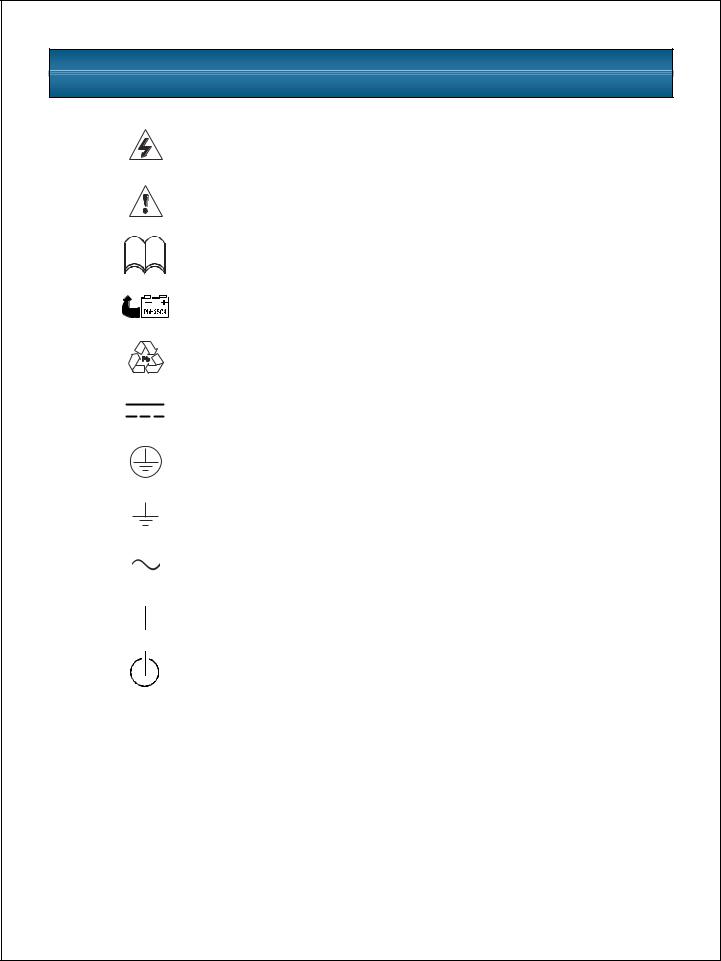
GLOSSARY OF SYMBOLS
•
Risk of electrical shock
Indicates caution followed by important instructions
iRequests the user to consult the manual
Indicates the unit contains a valve-regulated lead acid battery
Recycle
DC voltage
Equipment grounding conductor
Bonded to ground
AC voltage
ON
Standby
3

INTRODUCTION AND SYSTEM DESCRIPTION
Congratulations on your choice of the Liebert GXT5000R-208 Uninterruptible Power System (UPS). It provides conditioned power to microcomputers and other sensitive electronic equipment.
Upon generation, AC power is clean and stable. However, during transmission and distribution it may be subject to voltage sags, spikes, or complete power failure that may interrupt computer operations, cause data loss, and even damage equipment. The GXT5000R-208 protects equipment from these disturbances.
The GXT5000R-208 has a nominal power rating of 5,000VA, 3,750 W. Complete model specifications appear at the end of this manual.
At least one external battery cabinet must be connected to the GXT5000R-208 to form a complete “on-line” UPS system. Two different models of battery cabinets are available:
•The GXT5VBATT provides batteries only.
•The GXT5VBATTW120 provides batteries and an auxiliary transformer to provide up to 400VA at 120V.
Both battery cabinets provide two battery connectors to allow the daisy-chain connection of additional battery cabinets. The UPS may be used with either battery cabinet, depending on whether the additional 120V / 400VA power supply is needed.
For applications requiring 120V, one GXT5VBATTW120 should be the first battery cabinet located adjacent to the GXT5000R-208. The GXT5000R-208 requires a one-foot interconnect cable to provide power to the internal 208V step-down transformer.
If more than one battery cabinet is desired for additional backup battery time, additional GXT5VBATTs can be added. Only one GXT5VBATTW120 external battery cabinet can be used per UPS system.
For ease of use, the GXT5000R-208 utilizes light emitting diode (LED) displays to indicate “load percentage” and “battery capacity,” and fault indications. It also provides a self-diagnos- tics test, a combination ON/Manual Battery Test button, a combination Standby/Manual Bypass button, and a variety of relay alarm contacts.
4
MAJOR COMPONENTS
Transient Voltage Surge Suppression (TVSS) & EMI/RFI Filters
These UPS components provide surge protection and filter both electromagnetic interference (EMI) and radio frequency interference (RFI). They minimize any surges or interference present in the utility line and keep sensitive equipment protected.
Rectifier/Power Factor Correction (PFC) Circuit
In normal operation, the rectifier/PFC circuit converts utility AC power to regulated DC power for use by the inverter while ensuring that the waveshape of the input current used by the UPS is near ideal. Extracting this sinewave input current achieves two objectives: the utility power is used as efficiently as possible by the UPS, and the amount of distortion reflected on the utility is reduced. This results in cleaner power being available to other devices in the building not being protected by the GXT5000R-208.
Inverter
In normal operation, the inverter utilizes the DC output of the power factor correction circuit and “inverts” it into precise, regulated sinewave AC power. When utility power fails, the inverter takes power from the battery through the DC to DC converter and inverts it into alternating current. In both modes of operation, the UPS inverter is on-line and continuously generating clean, precise, regulated AC output power.
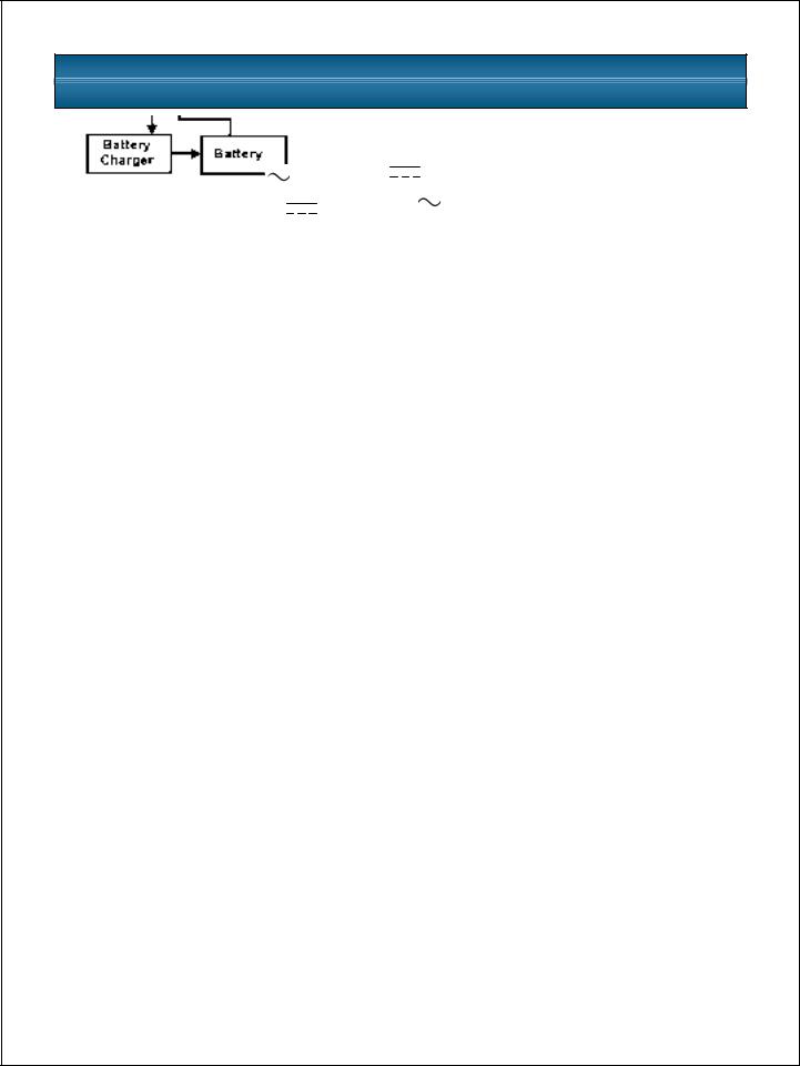
Battery Charger
The battery charger utilizes utility power and precisely regulates it to continuously “float” charge the battery system.
DC to DC Converter
The DC to DC converter utilizes energy from the battery system and raises the DC voltage to the optimum operating voltage for the inverter. This allows the inverter to operate continuously at its optimum efficiency and voltage, thus increasing reliability.
Battery
The GXT5VBATT and GXT5VBATTW120 employs valve-regulated, nonspillable, lead acid batteries. At an ambient temperature of 68°F to 77°F (20°C to 25°C) and with the UPS float charging, the battery design life will be maintained.
5

Auxiliary 120V / 400VA Power
The GXT5VBATTW120 battery cabinet also provides a transformer to provide up to 400VA of 120V power.
Dynamic Bypass
The GXT5000R-208 provides an alternate path for utility power to the connected load in the unlikely event of a UPS malfunction, such as overload, overtemperature, or an internal UPS failure. If a malfunction does occur, the UPS automatically transfers the connected load to bypass. Bypass operation is indicated by an alarm and illuminated Bypass LED (other LEDs also may be illuminated to indicate the diagnosed problem). To manually transfer the connected load from the inverter to bypass, press the Standby button  once.
once.
NOTE
The bypass power path does NOT protect the connected equipment from disturbances on the utility supply, such as spikes, sags, and failure.
6
Loading...