


 Loading...
Emerson Liebert Deluxe System-3 VE, DE, Liebert Deluxe System-3 DH, Liebert Deluxe System-3 VH User Manual


 Precision Cooling


 For Business-Critical Continuity™


 Liebert Deluxe System/3™


 Operation and Maintenance Manual


 50 and 60 Hz, 6-30 Ton DX Systems (DH/DE/VH/VE); 12-60 Ton CW Systems (FH/UH)


TABLE OF CONTENTS
1.0 INTRODUCTION . . . . . . . . . . . . . . . . . . . . . . . . . . . . . . . . . . . . . . . . . . . . . . . . . . . . . . . . . .1
1.1 System Description. . . . . . . . . . . . . . . . . . . . . . . . . . . . . . . . . . . . . . . . . . . . . . . . . . . . . . . . . . . 1
1.1.1 Compressorized Two-Step Systems . . . . . . . . . . . . . . . . . . . . . . . . . . . . . . . . . . . . . . . . . . . . . . . 1
1.1.2 Compressorized Four-Step Systems . . . . . . . . . . . . . . . . . . . . . . . . . . . . . . . . . . . . . . . . . . . . . . 1
1.1.3 Chilled Water Systems. . . . . . . . . . . . . . . . . . . . . . . . . . . . . . . . . . . . . . . . . . . . . . . . . . . . . . . . . 2
1.1.4 GLYCOOL™ (Chilled Glycol Cooling) Systems. . . . . . . . . . . . . . . . . . . . . . . . . . . . . . . . . . . . . . 2
1.1.5 Dual Source Cooling Systems . . . . . . . . . . . . . . . . . . . . . . . . . . . . . . . . . . . . . . . . . . . . . . . . . . . 2
2.0 INITIAL START-UP PROCEDURE. . . . . . . . . . . . . . . . . . . . . . . . . . . . . . . . . . . . . . . . . . . . . .3
2.0.1 Additional Considerations for Upflow Units. . . . . . . . . . . . . . . . . . . . . . . . . . . . . . . . . . . . . . . . 3
3.0 ADVANCED MICROPROCESSOR CONTROLS SETUP . . . . . . . . . . . . . . . . . . . . . . . . . . . . . . .4
3.1 Basics . . . . . . . . . . . . . . . . . . . . . . . . . . . . . . . . . . . . . . . . . . . . . . . . . . . . . . . . . . . . . . . . . . . . . 4
3.2 Display the Main Menu—AM Control . . . . . . . . . . . . . . . . . . . . . . . . . . . . . . . . . . . . . . . . . . . 4
3.3 Main Menu (AM)—Status/Alarm Data . . . . . . . . . . . . . . . . . . . . . . . . . . . . . . . . . . . . . . . . . . . 6
3.3.1 Active Alarms . . . . . . . . . . . . . . . . . . . . . . . . . . . . . . . . . . . . . . . . . . . . . . . . . . . . . . . . . . . . . . . . 6
3.3.2 Operating Status . . . . . . . . . . . . . . . . . . . . . . . . . . . . . . . . . . . . . . . . . . . . . . . . . . . . . . . . . . . . . 6
3.3.3 Alarm History Log . . . . . . . . . . . . . . . . . . . . . . . . . . . . . . . . . . . . . . . . . . . . . . . . . . . . . . . . . . . . 6
3.3.4 Run Hours Log . . . . . . . . . . . . . . . . . . . . . . . . . . . . . . . . . . . . . . . . . . . . . . . . . . . . . . . . . . . . . . . 6
3.3.5 Analog Sensors . . . . . . . . . . . . . . . . . . . . . . . . . . . . . . . . . . . . . . . . . . . . . . . . . . . . . . . . . . . . . . . 7
3.4 Main Menu (AM)—Setpoints/Setup . . . . . . . . . . . . . . . . . . . . . . . . . . . . . . . . . . . . . . . . . . . . . 7
3.4.1 View Setpoints Selection . . . . . . . . . . . . . . . . . . . . . . . . . . . . . . . . . . . . . . . . . . . . . . . . . . . . . . . 7
3.4.2 Setup System Selection . . . . . . . . . . . . . . . . . . . . . . . . . . . . . . . . . . . . . . . . . . . . . . . . . . . . . . . . 7
3.4.3 Run Diagnostics . . . . . . . . . . . . . . . . . . . . . . . . . . . . . . . . . . . . . . . . . . . . . . . . . . . . . . . . . . . . . 13
3.4.4 Change Passwords . . . . . . . . . . . . . . . . . . . . . . . . . . . . . . . . . . . . . . . . . . . . . . . . . . . . . . . . . . . 14
3.5 Main Menu (AM)—Date and Time . . . . . . . . . . . . . . . . . . . . . . . . . . . . . . . . . . . . . . . . . . . . . 14
3.6 Main Menu (AM)—Status Display . . . . . . . . . . . . . . . . . . . . . . . . . . . . . . . . . . . . . . . . . . . . . 15
3.7 Load Control Features . . . . . . . . . . . . . . . . . . . . . . . . . . . . . . . . . . . . . . . . . . . . . . . . . . . . . . . 15
3.7.1 Short Cycle Control . . . . . . . . . . . . . . . . . . . . . . . . . . . . . . . . . . . . . . . . . . . . . . . . . . . . . . . . . . 15
3.7.2 Sequential Load Activation Control . . . . . . . . . . . . . . . . . . . . . . . . . . . . . . . . . . . . . . . . . . . . . 15
3.7.3 Compressor Sequencing Control . . . . . . . . . . . . . . . . . . . . . . . . . . . . . . . . . . . . . . . . . . . . . . . . 15
3.8 Control Circuit Board. . . . . . . . . . . . . . . . . . . . . . . . . . . . . . . . . . . . . . . . . . . . . . . . . . . . . . . . 15
3.8.1 LCD Display Contrast . . . . . . . . . . . . . . . . . . . . . . . . . . . . . . . . . . . . . . . . . . . . . . . . . . . . . . . . 15
3.8.2 Nonvolatile Memory . . . . . . . . . . . . . . . . . . . . . . . . . . . . . . . . . . . . . . . . . . . . . . . . . . . . . . . . . . 16
3.8.3 DIP Switches. . . . . . . . . . . . . . . . . . . . . . . . . . . . . . . . . . . . . . . . . . . . . . . . . . . . . . . . . . . . . . . . 16
3.8.4 Control Outputs . . . . . . . . . . . . . . . . . . . . . . . . . . . . . . . . . . . . . . . . . . . . . . . . . . . . . . . . . . . . . 16
3.9 Communications. . . . . . . . . . . . . . . . . . . . . . . . . . . . . . . . . . . . . . . . . . . . . . . . . . . . . . . . . . . . 16
3.9.1 Monitor functions . . . . . . . . . . . . . . . . . . . . . . . . . . . . . . . . . . . . . . . . . . . . . . . . . . . . . . . . . . . . 17
3.9.2 View/Change Functions . . . . . . . . . . . . . . . . . . . . . . . . . . . . . . . . . . . . . . . . . . . . . . . . . . . . . . . 17
4.0 ADVANCED MICROPROCESSOR WITH GRAPHICS CONTROL SETUP . . . . . . . . . . . . . . . . . . .18
4.1 Basics . . . . . . . . . . . . . . . . . . . . . . . . . . . . . . . . . . . . . . . . . . . . . . . . . . . . . . . . . . . . . . . . . . . . 18
4.2 Display the Main Menu—AG Control . . . . . . . . . . . . . . . . . . . . . . . . . . . . . . . . . . . . . . . . . . . 20
4.3 Main Menu (AG)—Status Display. . . . . . . . . . . . . . . . . . . . . . . . . . . . . . . . . . . . . . . . . . . . . . 20
i

4.4 Main Menu (AG)—View/Set Alarms . . . . . . . . . . . . . . . . . . . . . . . . . . . . . . . . . . . . . . . . . . . . 20
4.4.1 Active Alarms . . . . . . . . . . . . . . . . . . . . . . . . . . . . . . . . . . . . . . . . . . . . . . . . . . . . . . . . . . . . . . . 20 4.4.2 Alarm History Log . . . . . . . . . . . . . . . . . . . . . . . . . . . . . . . . . . . . . . . . . . . . . . . . . . . . . . . . . . . 20 4.4.3 Setup Alarms . . . . . . . . . . . . . . . . . . . . . . . . . . . . . . . . . . . . . . . . . . . . . . . . . . . . . . . . . . . . . . . 21 4.4.4 Set Up Custom Alarms. . . . . . . . . . . . . . . . . . . . . . . . . . . . . . . . . . . . . . . . . . . . . . . . . . . . . . . . 22 4.4.5 View Water Detect Floor Plan (for optional LTM1000/LT750) . . . . . . . . . . . . . . . . . . . . . . . . 22 4.4.6 Setup Water Detect Floor Plan . . . . . . . . . . . . . . . . . . . . . . . . . . . . . . . . . . . . . . . . . . . . . . . . . 22
4.5 Main Menu (AG)—Operating Status . . . . . . . . . . . . . . . . . . . . . . . . . . . . . . . . . . . . . . . . . . . 23 4.6 Main Menu (AG)—View/Set Control Setpoints . . . . . . . . . . . . . . . . . . . . . . . . . . . . . . . . . . . 23 4.7 Main Menu (AG)—Setup System . . . . . . . . . . . . . . . . . . . . . . . . . . . . . . . . . . . . . . . . . . . . . . 23
4.7.1 Setup Operation . . . . . . . . . . . . . . . . . . . . . . . . . . . . . . . . . . . . . . . . . . . . . . . . . . . . . . . . . . . . . 24 4.7.2 Select Options . . . . . . . . . . . . . . . . . . . . . . . . . . . . . . . . . . . . . . . . . . . . . . . . . . . . . . . . . . . . . . . 25 4.7.3 Calibrate Sensors . . . . . . . . . . . . . . . . . . . . . . . . . . . . . . . . . . . . . . . . . . . . . . . . . . . . . . . . . . . . 25 4.7.4 Calibrate Valve Actuator . . . . . . . . . . . . . . . . . . . . . . . . . . . . . . . . . . . . . . . . . . . . . . . . . . . . . . 25 4.7.5 Select Control Algorithm . . . . . . . . . . . . . . . . . . . . . . . . . . . . . . . . . . . . . . . . . . . . . . . . . . . . . . 25 4.7.6 Select Humidity Sensing Mode . . . . . . . . . . . . . . . . . . . . . . . . . . . . . . . . . . . . . . . . . . . . . . . . . 26 4.7.7 Set Status Display . . . . . . . . . . . . . . . . . . . . . . . . . . . . . . . . . . . . . . . . . . . . . . . . . . . . . . . . . . . 26 4.7.8 Change Passwords . . . . . . . . . . . . . . . . . . . . . . . . . . . . . . . . . . . . . . . . . . . . . . . . . . . . . . . . . . . 26
4.8 Main Menu (AG)—Run Diagnostics . . . . . . . . . . . . . . . . . . . . . . . . . . . . . . . . . . . . . . . . . . . . 26
4.8.1 Show Inputs . . . . . . . . . . . . . . . . . . . . . . . . . . . . . . . . . . . . . . . . . . . . . . . . . . . . . . . . . . . . . . . . 27 4.8.2 Test Outputs . . . . . . . . . . . . . . . . . . . . . . . . . . . . . . . . . . . . . . . . . . . . . . . . . . . . . . . . . . . . . . . . 27 4.8.3 Test Control Board . . . . . . . . . . . . . . . . . . . . . . . . . . . . . . . . . . . . . . . . . . . . . . . . . . . . . . . . . . . 27 4.8.4 DIP Switches. . . . . . . . . . . . . . . . . . . . . . . . . . . . . . . . . . . . . . . . . . . . . . . . . . . . . . . . . . . . . . . . 28
4.9 Main Menu (AG)—Date and Time. . . . . . . . . . . . . . . . . . . . . . . . . . . . . . . . . . . . . . . . . . . . . . 28 4.10 Main Menu (AG)—Plot Graphs . . . . . . . . . . . . . . . . . . . . . . . . . . . . . . . . . . . . . . . . . . . . . . . . 28
4.10.1 Modify Plot Scales . . . . . . . . . . . . . . . . . . . . . . . . . . . . . . . . . . . . . . . . . . . . . . . . . . . . . . . . . . . |
29 |
4.11 Main Menu (AG)—Analog/Digital Inputs . . . . . . . . . . . . . . . . . . . . . . . . . . . . . . . . . . . . . . . . 29
4.11.1 Read Analog Inputs . . . . . . . . . . . . . . . . . . . . . . . . . . . . . . . . . . . . . . . . . . . . . . . . . . . . . . . . . . 29
4.11.2 Setup Analog Inputs. . . . . . . . . . . . . . . . . . . . . . . . . . . . . . . . . . . . . . . . . . . . . . . . . . . . . . . . . . 29
4.11.3 Read Digital Inputs . . . . . . . . . . . . . . . . . . . . . . . . . . . . . . . . . . . . . . . . . . . . . . . . . . . . . . . . . . 30
4.11.4 Set Up Digital Inputs . . . . . . . . . . . . . . . . . . . . . . . . . . . . . . . . . . . . . . . . . . . . . . . . . . . . . . . . . 30
4.12 Main Menu (AG)—View Run Hours Log. . . . . . . . . . . . . . . . . . . . . . . . . . . . . . . . . . . . . . . . . 30
4.12.1 View 24 Hour Run Time History . . . . . . . . . . . . . . . . . . . . . . . . . . . . . . . . . . . . . . . . . . . . . . . . 30
4.12.2 View Total Run Hours . . . . . . . . . . . . . . . . . . . . . . . . . . . . . . . . . . . . . . . . . . . . . . . . . . . . . . . . 30
4.13 Load Control Features . . . . . . . . . . . . . . . . . . . . . . . . . . . . . . . . . . . . . . . . . . . . . . . . . . . . . . . 30
4.13.1 Short Cycle Control . . . . . . . . . . . . . . . . . . . . . . . . . . . . . . . . . . . . . . . . . . . . . . . . . . . . . . . . . . 30
4.13.2 Sequential Load Activation Control . . . . . . . . . . . . . . . . . . . . . . . . . . . . . . . . . . . . . . . . . . . . . 30
4.13.3 Compressor Sequencing Control . . . . . . . . . . . . . . . . . . . . . . . . . . . . . . . . . . . . . . . . . . . . . . . . 31
4.14 Control Circuit Board. . . . . . . . . . . . . . . . . . . . . . . . . . . . . . . . . . . . . . . . . . . . . . . . . . . . . . . . 31
4.14.1 LCD Display Contrast . . . . . . . . . . . . . . . . . . . . . . . . . . . . . . . . . . . . . . . . . . . . . . . . . . . . . . . . 31
4.14.2 Nonvolatile Memory . . . . . . . . . . . . . . . . . . . . . . . . . . . . . . . . . . . . . . . . . . . . . . . . . . . . . . . . . . 31
4.14.3 DIP Switches. . . . . . . . . . . . . . . . . . . . . . . . . . . . . . . . . . . . . . . . . . . . . . . . . . . . . . . . . . . . . . . . 31
4.14.4 Control Outputs . . . . . . . . . . . . . . . . . . . . . . . . . . . . . . . . . . . . . . . . . . . . . . . . . . . . . . . . . . . . . 32
4.15 Communications. . . . . . . . . . . . . . . . . . . . . . . . . . . . . . . . . . . . . . . . . . . . . . . . . . . . . . . . . . . . 32
4.15.1 Monitor functions: . . . . . . . . . . . . . . . . . . . . . . . . . . . . . . . . . . . . . . . . . . . . . . . . . . . . . . . . . . . 32
4.15.2 View/Change Functions:. . . . . . . . . . . . . . . . . . . . . . . . . . . . . . . . . . . . . . . . . . . . . . . . . . . . . . . 32
ii

5.0 RESPONSE BY CONTROL TYPE—ADVANCED MICROPROCESSOR CONTROLS . . . . . . . . . . .33
5.1 Temperature Control . . . . . . . . . . . . . . . . . . . . . . . . . . . . . . . . . . . . . . . . . . . . . . . . . . . . . . . . 33
5.1.1 Cooling/Heating Required, in Percent (%) . . . . . . . . . . . . . . . . . . . . . . . . . . . . . . . . . . . . . . . . 33 5.1.2 Response to Control Types . . . . . . . . . . . . . . . . . . . . . . . . . . . . . . . . . . . . . . . . . . . . . . . . . . . . . 33 5.1.3 Cooling Operation. . . . . . . . . . . . . . . . . . . . . . . . . . . . . . . . . . . . . . . . . . . . . . . . . . . . . . . . . . . . 34 5.1.4 Heating Operation . . . . . . . . . . . . . . . . . . . . . . . . . . . . . . . . . . . . . . . . . . . . . . . . . . . . . . . . . . . 34
5.2 Humidity Control . . . . . . . . . . . . . . . . . . . . . . . . . . . . . . . . . . . . . . . . . . . . . . . . . . . . . . . . . . . 35
5.2.1 Dehumidification/Humidification Required, in Percent (%) . . . . . . . . . . . . . . . . . . . . . . . . . . 35 5.2.2 Control Types . . . . . . . . . . . . . . . . . . . . . . . . . . . . . . . . . . . . . . . . . . . . . . . . . . . . . . . . . . . . . . . 35 5.2.3 Dehumidification Operation . . . . . . . . . . . . . . . . . . . . . . . . . . . . . . . . . . . . . . . . . . . . . . . . . . . 35 5.2.4 Humidification Operation . . . . . . . . . . . . . . . . . . . . . . . . . . . . . . . . . . . . . . . . . . . . . . . . . . . . . 36 5.2.5 Control Types . . . . . . . . . . . . . . . . . . . . . . . . . . . . . . . . . . . . . . . . . . . . . . . . . . . . . . . . . . . . . . . 36
5.3 Load Control Features . . . . . . . . . . . . . . . . . . . . . . . . . . . . . . . . . . . . . . . . . . . . . . . . . . . . . . . 39
5.3.1 Short Cycle Control . . . . . . . . . . . . . . . . . . . . . . . . . . . . . . . . . . . . . . . . . . . . . . . . . . . . . . . . . . 39 5.3.2 Sequential Load Activation Control . . . . . . . . . . . . . . . . . . . . . . . . . . . . . . . . . . . . . . . . . . . . . 39 5.3.3 Compressor Sequencing Control . . . . . . . . . . . . . . . . . . . . . . . . . . . . . . . . . . . . . . . . . . . . . . . . 39
5.4 Analog Sensors . . . . . . . . . . . . . . . . . . . . . . . . . . . . . . . . . . . . . . . . . . . . . . . . . . . . . . . . . . . . . 40
5.4.1 Connecting the Analog Sensors . . . . . . . . . . . . . . . . . . . . . . . . . . . . . . . . . . . . . . . . . . . . . . . . . 40 5.4.2 Water Detection Display . . . . . . . . . . . . . . . . . . . . . . . . . . . . . . . . . . . . . . . . . . . . . . . . . . . . . . 41
5.5 Communications. . . . . . . . . . . . . . . . . . . . . . . . . . . . . . . . . . . . . . . . . . . . . . . . . . . . . . . . . . . . 42
5.5.1 Monitor functions: . . . . . . . . . . . . . . . . . . . . . . . . . . . . . . . . . . . . . . . . . . . . . . . . . . . . . . . . . . . 42 5.5.2 View/Change Functions:. . . . . . . . . . . . . . . . . . . . . . . . . . . . . . . . . . . . . . . . . . . . . . . . . . . . . . . 43
6.0 ALARM DESCRIPTIONS AND SOLUTIONS . . . . . . . . . . . . . . . . . . . . . . . . . . . . . . . . . . . . . .44
6.1 Standard Alarms . . . . . . . . . . . . . . . . . . . . . . . . . . . . . . . . . . . . . . . . . . . . . . . . . . . . . . . . . . . 44
6.1.1 Change Filter . . . . . . . . . . . . . . . . . . . . . . . . . . . . . . . . . . . . . . . . . . . . . . . . . . . . . . . . . . . . . . . 44 6.1.2 Compressor Overload . . . . . . . . . . . . . . . . . . . . . . . . . . . . . . . . . . . . . . . . . . . . . . . . . . . . . . . . . 44 6.1.3 Custom Alarms (Only With Advanced Controls) . . . . . . . . . . . . . . . . . . . . . . . . . . . . . . . . . . . 45 6.1.4 High Head Pressure . . . . . . . . . . . . . . . . . . . . . . . . . . . . . . . . . . . . . . . . . . . . . . . . . . . . . . . . . . 45 6.1.5 High Humidity . . . . . . . . . . . . . . . . . . . . . . . . . . . . . . . . . . . . . . . . . . . . . . . . . . . . . . . . . . . . . . 45 6.1.6 High Humidity and Low Humidity (Simultaneously) . . . . . . . . . . . . . . . . . . . . . . . . . . . . . . . 45 6.1.7 High Temperature . . . . . . . . . . . . . . . . . . . . . . . . . . . . . . . . . . . . . . . . . . . . . . . . . . . . . . . . . . . 45 6.1.8 High Temperature and Low Temperature (Simultaneously) . . . . . . . . . . . . . . . . . . . . . . . . . 45 6.1.9 Humidifier Problem . . . . . . . . . . . . . . . . . . . . . . . . . . . . . . . . . . . . . . . . . . . . . . . . . . . . . . . . . . 45 6.1.10 Loss of Air Flow . . . . . . . . . . . . . . . . . . . . . . . . . . . . . . . . . . . . . . . . . . . . . . . . . . . . . . . . . . . . . 46 6.1.11 Loss of Power . . . . . . . . . . . . . . . . . . . . . . . . . . . . . . . . . . . . . . . . . . . . . . . . . . . . . . . . . . . . . . . 46 6.1.12 Low Humidity . . . . . . . . . . . . . . . . . . . . . . . . . . . . . . . . . . . . . . . . . . . . . . . . . . . . . . . . . . . . . . . 46 6.1.13 Low Suction Pressure. . . . . . . . . . . . . . . . . . . . . . . . . . . . . . . . . . . . . . . . . . . . . . . . . . . . . . . . . 46 6.1.14 Low Temperature . . . . . . . . . . . . . . . . . . . . . . . . . . . . . . . . . . . . . . . . . . . . . . . . . . . . . . . . . . . . 46 6.1.15 Main Fan Overload. . . . . . . . . . . . . . . . . . . . . . . . . . . . . . . . . . . . . . . . . . . . . . . . . . . . . . . . . . . 46 6.1.16 Short Cycle . . . . . . . . . . . . . . . . . . . . . . . . . . . . . . . . . . . . . . . . . . . . . . . . . . . . . . . . . . . . . . . . . 46
6.2 Optional/Custom Alarms . . . . . . . . . . . . . . . . . . . . . . . . . . . . . . . . . . . . . . . . . . . . . . . . . . . . . 47
6.2.1 Loss of Water Flow . . . . . . . . . . . . . . . . . . . . . . . . . . . . . . . . . . . . . . . . . . . . . . . . . . . . . . . . . . . 47 6.2.2 Smoke Detected . . . . . . . . . . . . . . . . . . . . . . . . . . . . . . . . . . . . . . . . . . . . . . . . . . . . . . . . . . . . . 47 6.2.3 Standby GC Pump On . . . . . . . . . . . . . . . . . . . . . . . . . . . . . . . . . . . . . . . . . . . . . . . . . . . . . . . . 47 6.2.4 Standby Unit On. . . . . . . . . . . . . . . . . . . . . . . . . . . . . . . . . . . . . . . . . . . . . . . . . . . . . . . . . . . . . 47 6.2.5 Water Under Floor . . . . . . . . . . . . . . . . . . . . . . . . . . . . . . . . . . . . . . . . . . . . . . . . . . . . . . . . . . . 47
iii

7.0 COMPONENT OPERATION AND MAINTENANCE, CHECKS AND ADJUSTMENTS. . . . . . . . . . . .48
7.1 System Testing . . . . . . . . . . . . . . . . . . . . . . . . . . . . . . . . . . . . . . . . . . . . . . . . . . . . . . . . . . . . 48
7.1.1 Environmental Control Functions. . . . . . . . . . . . . . . . . . . . . . . . . . . . . . . . . . . . . . . . . . . . . . . 48
7.1.2 Electric Panel . . . . . . . . . . . . . . . . . . . . . . . . . . . . . . . . . . . . . . . . . . . . . . . . . . . . . . . . . . . . . . . 49
7.2 Filters . . . . . . . . . . . . . . . . . . . . . . . . . . . . . . . . . . . . . . . . . . . . . . . . . . . . . . . . . . . . . . . . . . . . 50
7.3 Blower Package . . . . . . . . . . . . . . . . . . . . . . . . . . . . . . . . . . . . . . . . . . . . . . . . . . . . . . . . . . . . 50
7.3.1 Fan Impellers and Bearings. . . . . . . . . . . . . . . . . . . . . . . . . . . . . . . . . . . . . . . . . . . . . . . . . . . . 50
7.3.2 Belts. . . . . . . . . . . . . . . . . . . . . . . . . . . . . . . . . . . . . . . . . . . . . . . . . . . . . . . . . . . . . . . . . . . . . . . 50
7.3.3 Electronic Variable Speed Drive (Inverter). . . . . . . . . . . . . . . . . . . . . . . . . . . . . . . . . . . . . . . . 51
7.4 Refrigeration System . . . . . . . . . . . . . . . . . . . . . . . . . . . . . . . . . . . . . . . . . . . . . . . . . . . . . . . . 51
7.4.1 Compressor Oil Level . . . . . . . . . . . . . . . . . . . . . . . . . . . . . . . . . . . . . . . . . . . . . . . . . . . . . . . . . 51
7.4.2 Suction Pressure. . . . . . . . . . . . . . . . . . . . . . . . . . . . . . . . . . . . . . . . . . . . . . . . . . . . . . . . . . . . . 52
7.4.3 Discharge Pressure. . . . . . . . . . . . . . . . . . . . . . . . . . . . . . . . . . . . . . . . . . . . . . . . . . . . . . . . . . . 52
7.4.4 Suction Superheat . . . . . . . . . . . . . . . . . . . . . . . . . . . . . . . . . . . . . . . . . . . . . . . . . . . . . . . . . . . 52
7.4.5 Thermostatic Expansion Valve . . . . . . . . . . . . . . . . . . . . . . . . . . . . . . . . . . . . . . . . . . . . . . . . . 52
7.4.6 Hot Gas Bypass Valve . . . . . . . . . . . . . . . . . . . . . . . . . . . . . . . . . . . . . . . . . . . . . . . . . . . . . . . . 53
7.4.7 Air Cooled Condenser. . . . . . . . . . . . . . . . . . . . . . . . . . . . . . . . . . . . . . . . . . . . . . . . . . . . . . . . . 54
7.4.8 Water/Glycol Cooled Condensers. . . . . . . . . . . . . . . . . . . . . . . . . . . . . . . . . . . . . . . . . . . . . . . . 55
7.4.9 Compressor Replacement. . . . . . . . . . . . . . . . . . . . . . . . . . . . . . . . . . . . . . . . . . . . . . . . . . . . . . 56
7.5 Humidifier. . . . . . . . . . . . . . . . . . . . . . . . . . . . . . . . . . . . . . . . . . . . . . . . . . . . . . . . . . . . . . . . . 57
7.5.1 Infrared Humidifier . . . . . . . . . . . . . . . . . . . . . . . . . . . . . . . . . . . . . . . . . . . . . . . . . . . . . . . . . . 57
7.5.2 Steam Generating Humidifier . . . . . . . . . . . . . . . . . . . . . . . . . . . . . . . . . . . . . . . . . . . . . . . . . . 59
7.6 Electric Reheat . . . . . . . . . . . . . . . . . . . . . . . . . . . . . . . . . . . . . . . . . . . . . . . . . . . . . . . . . . . . . 63
8.0 TROUBLESHOOTING . . . . . . . . . . . . . . . . . . . . . . . . . . . . . . . . . . . . . . . . . . . . . . . . . . . . .64
9.0 MAINTENANCE INSPECTION CHECKLIST—MONTHLY . . . . . . . . . . . . . . . . . . . . . . . . . . . . .70
10.0 MAINTENANCE INSPECTION CHECKLIST—SEMIANNUAL . . . . . . . . . . . . . . . . . . . . . . . . . . .71
iv

FIGURES
Figure 1 Advanced microprocessor control panel. . . . . . . . . . . . . . . . . . . . . . . . . . . . . . . . . . . . . . . . . . . . . . . 4 Figure 2 Advanced microprocessor (AM) control menu . . . . . . . . . . . . . . . . . . . . . . . . . . . . . . . . . . . . . . . . . . 5 Figure 3 Advanced microprocessor with graphics control panel . . . . . . . . . . . . . . . . . . . . . . . . . . . . . . . . . . 18 Figure 4 Advanced microprocessor with graphics (AG) control menu . . . . . . . . . . . . . . . . . . . . . . . . . . . . . 19 Figure 5 Analog input jumpers . . . . . . . . . . . . . . . . . . . . . . . . . . . . . . . . . . . . . . . . . . . . . . . . . . . . . . . . . . . . 40 Figure 6 Connecting the LT750. . . . . . . . . . . . . . . . . . . . . . . . . . . . . . . . . . . . . . . . . . . . . . . . . . . . . . . . . . . . 41 Figure 7 Hot gas bypass. . . . . . . . . . . . . . . . . . . . . . . . . . . . . . . . . . . . . . . . . . . . . . . . . . . . . . . . . . . . . . . . . . 53 Figure 8 Outdoor fan/condenser configuration. . . . . . . . . . . . . . . . . . . . . . . . . . . . . . . . . . . . . . . . . . . . . . . . 54 Figure 9 Infrared humidifier lamps . . . . . . . . . . . . . . . . . . . . . . . . . . . . . . . . . . . . . . . . . . . . . . . . . . . . . . . . 58 Figure 10 Steam generating humidifier . . . . . . . . . . . . . . . . . . . . . . . . . . . . . . . . . . . . . . . . . . . . . . . . . . . . . . 59 Figure 11 Run/drain switch. . . . . . . . . . . . . . . . . . . . . . . . . . . . . . . . . . . . . . . . . . . . . . . . . . . . . . . . . . . . . . . . 60 Figure 12 Steam generating humidifier control board . . . . . . . . . . . . . . . . . . . . . . . . . . . . . . . . . . . . . . . . . . 63
TABLES
Table 1 Default control and alarm setpoints . . . . . . . . . . . . . . . . . . . . . . . . . . . . . . . . . . . . . . . . . . . . . . . . . 7 Table 2 Setup functions and factory default values . . . . . . . . . . . . . . . . . . . . . . . . . . . . . . . . . . . . . . . . . . . . 8 Table 3 Select options. . . . . . . . . . . . . . . . . . . . . . . . . . . . . . . . . . . . . . . . . . . . . . . . . . . . . . . . . . . . . . . . . . . . 9 Table 4 DIP switch settings . . . . . . . . . . . . . . . . . . . . . . . . . . . . . . . . . . . . . . . . . . . . . . . . . . . . . . . . . . . . . . . 9 Table 5 Alarm default time delay . . . . . . . . . . . . . . . . . . . . . . . . . . . . . . . . . . . . . . . . . . . . . . . . . . . . . . . . . 11 Table 6 Control output LEDs. . . . . . . . . . . . . . . . . . . . . . . . . . . . . . . . . . . . . . . . . . . . . . . . . . . . . . . . . . . . . 16 Table 7 Alarm default time delay . . . . . . . . . . . . . . . . . . . . . . . . . . . . . . . . . . . . . . . . . . . . . . . . . . . . . . . . . 21 Table 8 Default control and alarm setpoints . . . . . . . . . . . . . . . . . . . . . . . . . . . . . . . . . . . . . . . . . . . . . . . . 23 Table 9 Setup functions and factory default values . . . . . . . . . . . . . . . . . . . . . . . . . . . . . . . . . . . . . . . . . . . 24 Table 10 Select options. . . . . . . . . . . . . . . . . . . . . . . . . . . . . . . . . . . . . . . . . . . . . . . . . . . . . . . . . . . . . . . . . . . 25 Table 11 DIP switch settings . . . . . . . . . . . . . . . . . . . . . . . . . . . . . . . . . . . . . . . . . . . . . . . . . . . . . . . . . . . . . . 28 Table 12 Control output LEDs. . . . . . . . . . . . . . . . . . . . . . . . . . . . . . . . . . . . . . . . . . . . . . . . . . . . . . . . . . . . . 32 Table 13 Changing factory-set sensor inputs . . . . . . . . . . . . . . . . . . . . . . . . . . . . . . . . . . . . . . . . . . . . . . . . . 40 Table 14 Additional connections available after unit delivery . . . . . . . . . . . . . . . . . . . . . . . . . . . . . . . . . . . 40 Table 15 Suction pressures . . . . . . . . . . . . . . . . . . . . . . . . . . . . . . . . . . . . . . . . . . . . . . . . . . . . . . . . . . . . . . . 52 Table 16 Discharge pressures . . . . . . . . . . . . . . . . . . . . . . . . . . . . . . . . . . . . . . . . . . . . . . . . . . . . . . . . . . . . . 52 Table 17 Humidifier canister part numbers . . . . . . . . . . . . . . . . . . . . . . . . . . . . . . . . . . . . . . . . . . . . . . . . . . 61 Table 18 Faults—canister generator humidifier . . . . . . . . . . . . . . . . . . . . . . . . . . . . . . . . . . . . . . . . . . . . . . 61 Table 19 Steam generating humidifier capacity. . . . . . . . . . . . . . . . . . . . . . . . . . . . . . . . . . . . . . . . . . . . . . . 62 Table 20 DIP switch settings for steam generating humidifier. . . . . . . . . . . . . . . . . . . . . . . . . . . . . . . . . . . 63 Table 21 Blower troubleshooting. . . . . . . . . . . . . . . . . . . . . . . . . . . . . . . . . . . . . . . . . . . . . . . . . . . . . . . . . . . 64 Table 22 Chilled water troubleshooting . . . . . . . . . . . . . . . . . . . . . . . . . . . . . . . . . . . . . . . . . . . . . . . . . . . . . 64 Table 23 Compressor and refrigeration system troubleshooting. . . . . . . . . . . . . . . . . . . . . . . . . . . . . . . . . . 65 Table 24 Dehumidification troubleshooting . . . . . . . . . . . . . . . . . . . . . . . . . . . . . . . . . . . . . . . . . . . . . . . . . . 67 Table 25 Glycol pumps troubleshooting . . . . . . . . . . . . . . . . . . . . . . . . . . . . . . . . . . . . . . . . . . . . . . . . . . . . . 67 Table 26 Humidifier—steam generator troubleshooting . . . . . . . . . . . . . . . . . . . . . . . . . . . . . . . . . . . . . . . . 68 Table 27 Humidifier—infrared troubleshooting . . . . . . . . . . . . . . . . . . . . . . . . . . . . . . . . . . . . . . . . . . . . . . . 69 Table 28 Reheat troubleshooting. . . . . . . . . . . . . . . . . . . . . . . . . . . . . . . . . . . . . . . . . . . . . . . . . . . . . . . . . . . 69
v

vi

Introduction
1.0INTRODUCTION
1.1System Description
Liebert Deluxe environmental control systems are available in several configurations. Each configuration can operate with either Advanced Microprocessor Controls (AM), or Advanced Microprocessor Controls with Graphics (AG). A brief description of each, including operational differences, are listed below. Check model numbers to see what is supplied with your unit.
1.1.1Compressorized Two-Step Systems
These systems may be air, water, or glycol cooled - depending on the heat rejection method selected.
Cooling
Two stages of mechanical refrigeration
Heating
Three stages of electric reheat standard; steam/hot water, hot gas on water and glycol-cooled systems optional
Humidification
Infrared standard, steam grid and steam generating optional
Dehumidification
Utilizes the lag compressor
1.1.2Compressorized Four-Step Systems
The 4-stage systems have all the features of a compressorized 2-stage system plus cylinder unloaders on one head of each compressor. This permits the compressors to operate at a reduced level and increases energy efficiency during low load conditions. The system responds to an increasing room load with either a two step or a four step process of increasing the unit's cooling.
Cooling
Four stages of mechanical refrigeration:
1.Lead compressor at reduced capacity.
2.Lead and lag compressors at reduced capacity.
3.Lead compressor at full capacity; lag compressor at reduced capacity.
4.Lead and lag compressors at full capacity.
Heating
Three stages of electric reheat standard; hot water/steam optional
Humidification
Infrared standard, steam grid and steam generating optional
Dehumidification
Utilizes the lag compressor
1

Introduction
1.1.3Chilled Water Systems
These systems utilize a central chiller and control cooling by modulating a control valve in the chilled water line.
Cooling
Modulating output water valve
Heating
Three stages of electric reheat standard; steam/hot water optional
Humidification
Infrared standard, steam grid and steam generating optional
Dehumidification
Chilled water valve opens proportionally in response to room needs
1.1.4GLYCOOL™ (Chilled Glycol Cooling) Systems
GLYCOOL™ systems have all of the features of a compressorized water or glycol system, plus a second cooling coil that is connected into the water circuit. When fluid temperature is sufficiently low (below room temperature), cooling is provided by circulating the fluid through the second cooling coil (with the flow controlled by a motorized valve). This is then the primary cooling source, greatly reducing the compressor operation.
Cooling
Modulated cooling valve opens proportionally to match room needs (primary), two or four stages of mechanical refrigeration (secondary)
Heating
Three stages of electric reheat standard
Humidification
Infrared standard; steam generating optional
Dehumidification
Utilizes the lag compressor
1.1.5Dual Source Cooling Systems
This system has all the features of a compressorized system but adds a second cooling coil that is connected to a source of chilled water. This second coil is controlled by a modulating control valve. It is the primary source of cooling and dehumidification so compressor operation is reduced.
Cooling
Second coil opens proportionally in response to the room needs (primary), two or four stages of mechanical refrigeration (secondary)
Heating
Three stages of electric reheat standard
Humidification
Infrared standard; steam generating optional
Dehumidification
Standard Controls use the lag compressor. Advanced Controls use the chilled water valve and then the lag compressor if required by the load.
2
Initial Start-Up Procedure
2.0INITIAL START-UP PROCEDURE
Before beginning start-up, make certain that unit was installed according to the instructions in the Installation Manual. All exterior panels must be in place.
Locate the Start-Up form supplied with your unit documents. Complete the form during your start-up and mail it to Liebert when start-up is completed. Contact your Liebert supplier if you have any questions or problems during your unit installation, start-up, or operation.
! WARNING
Potentially lethal voltages exist within this equipment during operation. Observe all cautions and warnings on the unit and in this manual. Failure to do so could result in serious injury or death. Only qualified service and maintenance personnel should work with this equipment.
1.Disconnect all power to the environmental control unit.
2.Tighten all electrical wiring connections on electric panel and at all major components such as compressors, reheats, humidifiers and motors which may have loosened during shipping.
3.Remove all line voltage fuses except the main fan fuses at the far right of the electric panel and the Control Voltage fuses at the far left of the electric panel. For units supplied with circuit breakers, open them instead of removing fuses.
4.Turn on power and check line voltage on main unit disconnect switch. Line voltage must be within 10% of nameplate voltage.
5.Turn ON main unit disconnect switch and check secondary voltage at transformer T1. Voltage at T1 must be 24 VAC ±2.5 VAC (check at TB1-1 and TB1-8). T1 voltage must not exceed 28 VAC. Change primary tap if necessary.
6.Push ON button. Blower will start and ON lamp will light (lighted switch on Standard Controls only).
7.If you do not want your unit to operate at factory default settings, set temperature and humidity setpoints and sensitivity, alarms, and other control functions. Refer to 3.0 - Advanced Microprocessor Controls Setup or to Advanced Microprocessor with Graphics Control Setup on page 18.
8.Turn OFF main unit disconnect and main breaker. Unit ON button should be OFF.
9.Replace all fuses you removed during step three (or reset circuit breakers).
10.Restore power to unit; turn ON the main unit disconnect switch.
11.Check the current draw on all line voltage components and match with serial tag.
12.Push ON button, putting the unit into operation.
13.Check for unusual noises and vibration.
14.Check all refrigerant and water lines for leaks.
15.Test all functions of your unit for proper operation.
Return completed startup form to:
Liebert Corporation
1050 Dearborn Drive P.O. Box 29186 Columbus, OH 43229
2.0.1Additional Considerations for Upflow Units
These units are manufactured with factory supplied adjustable motor sheaves. Due to variations in applications, a fixed motor pulley may be desired and can be substituted for the adjustable sheave after obtaining and confirming the desired air flow. This will reduce vibration and wear on the belts and pulleys. Consult Liebert Applications Engineering for more information.
3
Advanced Microprocessor Controls Setup
3.0ADVANCED MICROPROCESSOR CONTROLS SETUP
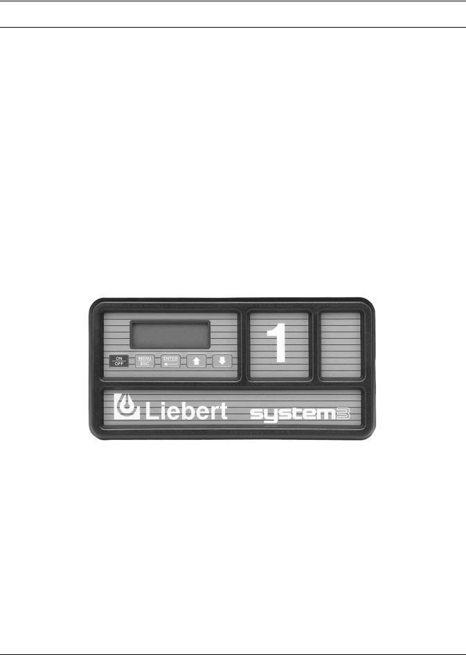
The Advanced Microprocessor (AM) Control for your Liebert Deluxe unit features an easy to use menu driven LCD display. The menus, control features, and circuit board details are described in this section. For more control details refer to 5.0 - Response by Control Type—Advanced Microprocessor Controls, and for more alarm information refer to 6.0 - Alarm Descriptions and Solutions.
3.1Basics
Control keys include ON/OFF, MENU/ESCAPE, ENTER, Increase (UP) arrow, and Decrease (DOWN) arrow. Refer to Figure 1. These keys are used to move through the menus as prompted on the LCD display (refer to Figure 2).
To turn the unit on, press the ON/OFF key after power is applied. To turn the unit off, press the ON/ OFF key before power is disconnected.
Active alarms are displayed on the LCD screen. An audible beeper also annunciates alarms. To silence an alarm, press the ENTER key as prompted on the display. The unit stores the 10 most recent alarms for review.
Setpoints, DIP switch settings, and other selections were made on your unit before testing at the factory. Setpoints were chosen based on typical operating experience. Other selections were made based on options included with your unit. Make adjustments to the factory default selections ONLY if they do not meet your specifications. When entering setpoints, time delays, etc., the allowable ranges are displayed and may require a password, if enabled.
Figure 1 Advanced microprocessor control panel
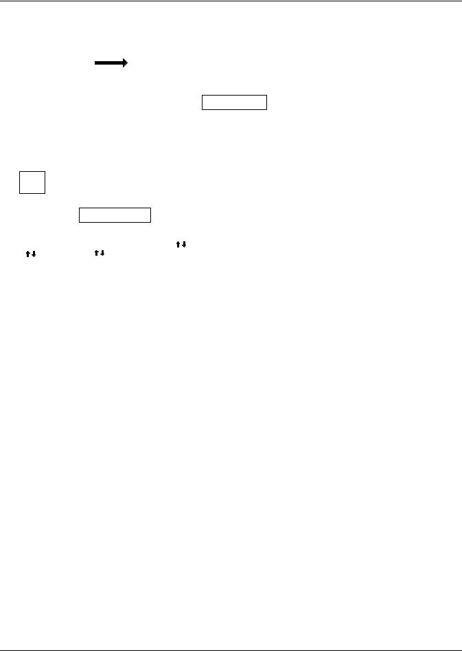
3.2Display the Main Menu—AM Control
Press the MENU/ESC key to display the Main Menu. The menu selections include:
STATUS/ALARM DATA SETPOINTS/SETUP DATE AND TIME STATUS DISPLAY
4
Advanced Microprocessor Controls Setup
Figure 2 Advanced microprocessor (AM) control menu
|
|
|
|
|
|
|
|
|
|
|
|
|
|
|
|
|
|
|
|
|
|
|
|
|
|
|
|
|
|
|
|
|
|
|
|
|
|
|
|
|
|
Main Menu |
|
|
|
|
|
|
|
|
|
|
|
|
|
|
|
|
|
|
|
|
|
|||||||
|
|
|
|
|
|
|
|
|
|
|
|
|
|
Normal |
|
|
|
|
|
|
|
|
|
|
|
|
|
|
|
|
|
|
|
|
|
|
|
|
|
|
|
|
|
|
|
|
|
|
|
|
||||||||||||||||||||
|
|
|
|
|
|
|
|
|
|
|
|
|
|
|
72° 50% Reheat |
|
|
|
Status/Alarm Data |
|
|
|
|
|
|
|
|
|
|
|
|
|
|
|
|
|
|
|
|
|
||||||||||||||||||||||||||||||
|
|
|
|
|
|
|
|
|
|
|
|
|
|
Display |
|
|
Cooling |
|
|
|
|
|
|
|
|
|
Setpoints/Setup |
|
|
|
|
|
|
|
|
|
|
|
|
|
|
|
|
|
|
|
|
|
||||||||||||||||||||||
|
|
|
|
|
|
|
|
|
|
|
|
|
|
|
|
|
|
|
|
|
Dehumidifying |
|
|
|
|
|
|
Date and Time |
|
|
|
|
|
|
|
|
|
|
|
|
|
|
|
|
|
|
|
|
|
|||||||||||||||||||||
|
|
|
|
|
|
|
|
|
|
|
|
|
|
|
|
|
|
|
|
|
No Alarms Present |
|
|
|
|
|
|
Status Display |
|
|
|
|
|
|
|
|
|
|
|
|
|
|
|
|
|
|
|
|
|
|||||||||||||||||||||
|
|
|
|
|
|
|
|
|
|
|
|
|
|
|
|
|
|
|
|
|
|
|
|
|
|
|
|
|
|
|
|
|
|
|
|
|
|
|
|
|
|
|
|
|
|
|
|
|
|
|
|
|
|
|
|
|
|
|
|
|
|
|
|
|
|
|
|
|
|
|
|
|
|
|
|
|
|
|
|
|
|
|
|
|
|
|
|
|
|
|
|
|
|
|
|
|
|
|
|
|
|
|
|
|
|
|
|
|
|
|
|
|
|
|
|
|
|
|
|
|
|
|
|
|
|
|
|
|
|
|
|
|
|
|
|
|
|
|
|
|
|
|
|
|
|
|
|
|
|
|
|
|
|
Status Alarm Data |
|
|
|
|
|
|
|
|
|
|
|
|
|
Setpoints/Setup |
|
|
|
|
|
|
Date and Time |
|
|
|
Status Display |
|
||||||||||||||||||||||||||||||||
|
|
|
|
|
|
|
|
|
|
|
|
|
|
|
|
|
|
|
|
|
|
|
|
|
|
|
|
|
|
|
|
|
|
|
|
|
|
|
|
|
|
|
|
|
|
|
|
|
|
|
|
|
|
|
|
|
|
|
|
|
|
|
|
|
|
|
||||
|
|
|
|
|
|
|
|
|
|
|
|
Active Alarms |
|
|
|
|
|
|
|
|
|
|
|
|
|
|
|
View Setpoints |
|
|
|
15-APR-2001 09:30:00 |
|
|
75°F 59% RH |
|
||||||||||||||||||||||||||||||||||
|
|
|
|
|
|
|
|
|
|
|
|
Operating Status |
|
|
|
|
|
|
|
|
|
|
|
Setup System |
|
|
|
|
|
|
|
|
|
|
|
|
|
|
|
|
|
Cooling |
|
|||||||||||||||||||||||||||
|
|
|
|
|
|
|
|
|
|
|
|
Alarm History Log |
|
|
|
|
|
|
|
|
|
|
|
Run Diagnostics |
|
|
|
|
|
|
ENTER to change |
|
|
Dehumidifying |
|
|||||||||||||||||||||||||||||||||||
|
|
|
|
|
|
|
|
|
|
|
|
Run Hours Log |
|
|
|
|
|
|
|
|
|
|
|
|
|
|
|
Change Passwords |
|
|
|
|
|
ESCape to exit |
|
|
No Alarms Present |
|
||||||||||||||||||||||||||||||||
|
|
|
|
|
|
|
|
|
|
|
|
Analog Sensors |
|
|
|
|
|
|
|
|
|
|
|
|
|
|
|
|
|
|
|
|
|
|
|
|
|
|
|
|
|
|
|
|
|
|
|
|
|
|
|
|
|
|
|
|
|
|
|
|
|
|
|
|
||||||
|
|
|
|
|
|
|
|
|
|
|
|
|
|
|
|
|
|
|
|
|
|
|
|
|
|
|
|
|
|
|
|
|
|
|
|
|
|
|
|
|
|
|
|
|
|
|
|
|
|
|
|
|
|
|
|
|
|
|
|
|
|
|
|
|
|
|
|
|||
|
|
|
|
|
|
|
|
|
|
|
|
|
|
|
|
|
|
|
|
|
|
|
|
|
|
|
|
|
|
|
|
|
|
|
|
|
|
|
|
|
|
|
|
|
|
|
|
|
|
|
|
|
|
|
|
|
|
|
|
|
||||||||||
|
|
|
|
|
|
|
|
|
|
|
|
|
|
|
|
|
|
|
|
|
|
|
|
|
|
|
|
|
|
|
|
|
|
|
|
|
|
|
|
|
|
|
|
|
|
|
|
|
|
|
|
|
|
|
|
|
|
|
|
|
|
|
|
|
||||||
|
Active |
|
Operating |
|
|
Alarm |
|
|
|
|
|
Run |
|
|
Analog |
|
|
|
View |
|
|
Setup |
|
|
Run |
|
|
|
Change |
|
|
|
||||||||||||||||||||||||||||||||||||||
|
Alarms |
|
|
Status |
|
|
History Log |
|
|
|
Hours Log |
|
|
Sensors |
|
Setpoints |
|
|
System |
|
|
Diagnostics |
|
Passwords |
|
|
|
|||||||||||||||||||||||||||||||||||||||||||
|
|
|
|
|
|
|
|
|
|
|
|
|
|
|
|
|
|
|
|
|
|
|
|
|
|
|
|
|
|
|
|
|
|
|
|
|
|
|
|
|
|
|
|
|
|
|
|
|
|
|
|
|
|
|
|
|
|
|
|
|
|
|
|
|
|
|||||
|
|
|
|
|
|
|
|
|
|
|
|
|
|
|
|
|
|
|
|
|
|
|
|
|
|
|
|
|
|
|
|
|
|
|
|
|
|
|
|
|
|
|
|
|
|
|
|
|
|
|
|
|
|
|
|
|
|
|
|
|
|
|
|
|
|
|||||
No Alarms Present |
|
|
|
Alarm History Log |
|
|
|
Analog Sensors |
|
|
View Setpoints |
|
|
|
|
Run Diagnostics |
|
Change Passwords |
|
|||||||||||||||||||||||||||||||||||||||||||||||||||
|
|
|
|
|
|
|
|
|
|
|
|
|
|
|
|
|
|
|
|
|
|
|
|
|
|
|
|
|
|
|
|
|
|
|
|
|
|
|
|
|
|
|
|
|
|
|
|
|
|
|
|
|
|
|
|
|
|
|
|
|
|
|
|
|
|
|||||
|
|
OR |
|
|
Alarm 01 of 03 |
|
|
|
|
|
Analog 1(2,3,4)xx |
|
|
Temp Setpoints |
|
|
Show Inputs |
Setpoint Password |
||||||||||||||||||||||||||||||||||||||||||||||||||||
|
Alarm 01 of 01 |
|
|
|
15-APR-09:20:45 |
|
|
|
|
|
|
|
AD#1(2,3,4) |
|
|
|
|
Sensitivity |
|
|
|
|
|
|
|
Test Outputs |
|
Setup Password |
|
|||||||||||||||||||||||||||||||||||||||||
|
High Head PR |
|
|
High Humidity |
|
|
|
|
|
|
|
Use |
/ to Scroll |
|
|
Hi Temp Alarm |
|
|
|
Test Control Board |
|
|
|
|
|
|
|
|
|
|
||||||||||||||||||||||||||||||||||||||||
|
Use / to Scroll |
|
|
Use |
/ to Scroll |
|
|
|
|
|
|
|
ESCape to Exit |
|
|
|
|
Lo Temp Alarm |
|
|
|
|
|
|
|
|
|
|
|
|
|
|
|
|
|
|
|
|
|
|||||||||||||||||||||||||||||||
|
|
|
|
|
|
|
|
|
|
|
|
|
|
|
|
|
|
|
|
|
|
|
|
|
|
|
|
|
||||||||||||||||||||||||||||||||||||||||||
|
|
|
|
|
|
|
|
|
|
|
|
|
|
|
|
|
|
|
|
|
|
|
|
|
|
|
|
|
|
|
|
|
|
|
|
|
|
|
|
Hi Hum Alarm |
|
|
|
|
|
|
|
|
|
|
|
|
|
|
|
|
|
|
|
|
|
|||||||||
|
|
|
|
|
|
|
|
|
|
|
|
|
|
|
|
|
|
|
|
|
|
|
|
|
|
|
|
|
|
|
|
|
|
|
|
|
|
|
|
|
|
|
|
|
|
|
|
|
|
|
|
|
|
|
|
|
|
|
|
|
||||||||||
|
|
|
|
Operating Status |
|
|
|
|
|
Run |
Hours Log |
|
|
|
|
|
|
|
|
Lo Hum Alarm |
|
|
|
|
|
|
|
|
|
|
|
|
|
|
|
|
|
|
|
|
|
|||||||||||||||||||||||||||||
|
|
|
|
|
|
|
|
|
|
|
|
|
|
|
|
|
|
|
|
|
|
|
|
|
|
|
|
|
|
|
|
|
|
|
|
|
|
|
|
|
|
|
|
|
|
|
|
|
|
|
|
|
|
|
|
|
|
|
|
|
|
|
|
|
|
|
|
|
|
|
|
|
|
|
DX Cool % |
|
|
|
|
|
C1 |
|
|
|
|
|
|
|
|
|
|
|
|
|
|
|
|
|
|
|
|
|
|
|
|
|
|
|
|
|
|
|
|
|
|
|
|
|
|
|
|
|
|
|
|
|
|
|
|
||||||||||||
|
|
|
|
Heat % |
|
|
|
|
|
|
|
|
C2 |
|
|
|
|
|
|
|
|
|
|
|
|
|
|
|
|
|
|
|
|
|
|
|
|
|
|
|
|
|
|
|
|
|
|
|
|
|
|
|
|
|
|
|
|
|
|
|
|
|||||||||
|
|
|
|
Econo Cool |
%** |
|
|
|
|
Glycool™ |
|
|
|
|
|
|
|
|
|
|
|
|
|
|
|
|
|
|
|
|
|
|
|
|
|
|
|
|
|
|
|
|
|
|
|
|
|
|
|
|
|
|||||||||||||||||||
|
|
|
|
CW Valve %** |
|
|
|
|
|
Fan |
|
|
|
|
|
|
|
|
|
|
|
|
|
|
|
|
|
|
|
|
|
|
|
|
|
|
|
|
|
|
|
|
|
|
|
|
|
|
|
|
|
|||||||||||||||||||
|
|
|
|
Dx Deh/Hum |
|
|
|
|
|
Hum |
|
|
|
|
|
|
|
|
|
|
|
|
|
|
|
|
|
|
|
|
|
|
|
|
|
|
|
|
|
|
|
|
|
|
|
|
|
|
|
|
|
|||||||||||||||||||
|
|
|
|
|
|
|
|
|
|
|
|
|
|
|
|
|
|
|
RH1 |
|
|
|
|
|
|
|
|
|
|
|
|
|
|
|
|
|
|
|
|
|
|
|
|
|
|
|
|
|
|
|
|
|
|
|
|
|
|
|
|
|
||||||||||
|
|
|
|
|
|
|
|
|
|
|
|
|
|
|
|
|
|
|
RH2 |
|
|
|
|
|
|
|
|
|
|
|
|
|
|
|
|
|
|
|
|
|
|
|
|
|
|
|
|
|
|
|
|
|
|
|
|
|
|
|
|
|
||||||||||
|
|
|
|
|
|
|
|
|
|
|
|
|
|
|
|
|
|
|
RH3 - selectable |
|
|
|
|
|
|
|
|
|
|
|
|
|
|
|
|
|
|
|
|
|
|
|
|
|
|
|
|
|
|
|
|
|
|
|
|
|
|
|
||||||||||||
|
|
|
|
|
|
|
|
|
|
|
|
|
|
|
|
|
|
|
CW Coil** |
|
|
|
|
|
|
|
|
|
|
|
|
|
|
|
|
|
|
|
|
|
|
|
|
|
|
|
|
|
|
|
|
|
|
|
|
|
|
|
|
|
||||||||||
|
|
|
|
|
|
|
|
|
|
|
|
|
|
|
|
|
|
|
|
|
|
|
|
|
|
|
|
|
|
|
|
|
|
|
|
|
|
|
|
|
|
|
|
|
|
|
|
|
|
|
|
|
|
|
|
|
|
|
|
|
|
|
|
|
|
|
|
|
|
|
|
|
|
|
|
|
|
|
|
|
|
|
|
|
|
|
|
|
|
|
|
|
|
|
|
|
|
|
|
|
|
|
|
|
|
|
|
|
|
||||||||||||||||||||||||||||||||
Setup |
Operation |
Calibrate |
Sensors |
|
|
|
|
|
|
|
|
|
|
|
|
|
|
|
Setup |
Alarms |
Hum Control Method |
|
|
|
|
|
Calibrate |
Actuator |
||||||||||||||||||||||||||||||||||||||||||
|
|
|
|
|
|
|
|
|
|
|
|
|
|
|
|
|
|
|
|
|
|
|
|
|
|
|
|
|
|
|
|
|
|
|
|
|
|
|
|
|
|
|
|
|
|
|
|
|||||||||||||||||||||||
Cold Start TO |
|
|
|
|
|
|
|
|
|
|
|
|
|
|
|
|
|
|
|
|
|
|
|
|
|
Set Time Delays |
|
|
|
|
Relative |
|
|
|
|
|
|
|
|
|
|
|||||||||||||||||||||||||||||
|
|
|
|
Show DIP Switches (1-7) |
|
|
|
|
|
|
|
|
|
|
|
|
|
|
|
|
|
|
|
|
|
|
|
|
||||||||||||||||||||||||||||||||||||||||||
|
Restart TO |
|
|
|
|
|
|
|
|
|
|
|
Enable Alarms |
|
|
|
|
Absolute |
|
|
|
|
|
|
|
|
|
|
|
|||||||||||||||||||||||||||||||||||||||||
|
|
|
|
|
|
|
|
|
|
|
|
|
|
|
|
|
|
|
|
|
|
|
|
|
|
|
|
|
|
|
|
|
|
|
|
|
|
|
|
|
|
|
||||||||||||||||||||||||||||
|
IR Fill Rate |
|
|
|
|
|
|
|
|
|
|
|
|
|
|
|
|
|
|
|
|
|
|
|
|
|
|
|
Enable Common |
|
|
|
|
|
|
|
|
|
|
|
|
|
|
|
|
|
|
|
|
|
|
|
|
|
||||||||||||||||
|
|
|
|
|
|
|
|
|
|
|
|
|
Select Control Type |
|
|
|
|
|
|
|
|
|
|
|
Analog Setup |
|
|
|
|
|
|
|||||||||||||||||||||||||||||||||||||||
|
F/C Degrees |
|
|
|
|
|
|
|
|
|
|
|
|
|
Alarm |
|
|
|
|
|
|
|
|
|
|
|
||||||||||||||||||||||||||||||||||||||||||||
|
Min CW Temp |
|
|
|
|
|
|
|
|
|
|
|
|
Intelligent |
|
|
|
|
|
|
Set Custom Alarms |
|
|
|
|
|
|
|
A/O Input 1 (2,3,4) |
|
|
|
|
|
|
|||||||||||||||||||||||||||||||||||
|
CW/HW Flush |
|
|
|
|
|
|
|
|
|
|
|
|
Proportional |
|
|
|
|
|
|
|
Select Alarm |
|
|
|
|
|
|
|
|
|
|
Slope |
|
||||||||||||||||||||||||||||||||||||
|
|
|
|
|
|
|
|
|
|
|
|
|
|
|
|
|
|
|
|
|
Tunable PID |
|
|
|
|
|
|
|
Change Custom |
|
|
|
|
|
|
|
Text |
|
|
|
|
|
|
|
|
|
|
|||||||||||||||||||||||
|
|
|
|
|
|
|
|
|
|
|
|
|
|
|
|
|
|
|
|
|
|
|
|
|
|
|
|
|
|
|
|
|
|
|
|
|
|
|
|
|
|
|
||||||||||||||||||||||||||||
|
|
|
|
|
|
Select Options |
|
|
|
|
|
Proportional |
|
|
TXT 1,2 |
|
|
|
|
|
|
|
|
|
|
Intercept |
|
|
|
|
|
|
||||||||||||||||||||||||||||||||||||||
|
|
|
|
|
|
|
|
|
|
|
|
|
|
|
|
|
|
|
|
|
|
|
Derivative Gain |
|
|
|
|
|
|
|
|
|
|
|
|
|
|
|
|
|
|
|
|
|
|
|
|
|
|
|
|
|
|
|
|
|
|
|
|
|||||||||||
|
|
|
|
|
|
Heating |
|
|
|
|
|
|
|
|
|
|
|
|
|
|
|
|
|
|
|
|
|
|
|
|
|
|
|
|
|
|
|
|
|
|
|
|
|
|
|
|
|
|
|
|
|
|
||||||||||||||||||
|
|
|
|
|
|
|
|
|
|
|
|
|
|
|
|
|
|
|
|
|
|
|
|
|
|
|
|
|
|
|
|
|
|
|
|
|
|
|
|
|
|
|
Set Status Display |
|
|
|
||||||||||||||||||||||||
|
|
|
|
|
|
Humidifier |
|
|
|
|
|
|
|
|
|
Integral Gain |
|
|
|
|
|
|
|
|
|
|
|
|
|
|
|
|
|
|
|
|
|
|
|
|
|
|
|
|
||||||||||||||||||||||||||
|
|
|
|
|
|
|
|
|
|
|
|
|
|
|
|
|
|
|
|
|
|
|
|
|
|
|
|
|
|
|
|
|
|
|
|
|
|
|
|
|
|
|
|
|
|
|
|
|
|
|
||||||||||||||||||||
|
|
|
|
|
|
Dehumidifier |
|
|
|
|
|
|
|
|
|
|
|
|
|
|
|
|
|
|
|
|
|
|
|
|
|
|
|
|
|
|
|
|
|
|
|
|
|
|
|
|
|
|
|
|
|
|
|
|
|
|
|
|
|
|
|
|
|
|||||||
|
|
|
|
|
|
Hum Pan |
|
|
|
|
|
|
|
|
|
|
|
|
|
|
|
|
|
|
|
|
|
|
|
|
|
Alarms Available* |
|
|
|
|
|
|
|
|
|
|
|
|
|
|
|
|
|
|
|
|
|
|||||||||||||||||
|
|
|
|
|
|
Hot Gas Reh |
|
|
|
|
|
|
|
|
|
|
|
|
|
|
|
|
|
|
|
|
|
|
|
|
|
|
|
|
|
|
|
|
|
|
|
|
|
|
|
|
|
|
|
|||||||||||||||||||||
|
|
|
|
|
|
|
|
|
|
|
|
|
|
Standard Alarms |
|
|
|
|
Custom Alarms |
|
|
|
|
|
|
|
|
|
|
|
|
|
|
|
|
|
|
|
|
|
||||||||||||||||||||||||||||||
|
|
|
|
|
|
Heat Stages |
|
|
|
|
|
|
|
|
|
|
|
|
|
|
|
|
|
|
|
|
|
|
|
|
|
|
|
|
|
|
|
|
|
|||||||||||||||||||||||||||||||
|
|
|
|
|
|
Dehum Stages |
|
|
|
|
Humidifier Problems |
|
|
|
|
Programmed Alarm Messages |
|
|
|
|
|
|
|
|
|
|
|
|
|
|||||||||||||||||||||||||||||||||||||||||
|
|
|
|
|
|
|
|
|
|
|
|
|
|
|
|
|
|
|
|
|
|
High Head Pressure |
|
|
|
|
|
|
Water Under Floor |
|
|
|
|
|
|
|
|
|
|
|
|
|
|
|||||||||||||||||||||||||||
|
|
|
|
|
|
|
|
|
|
|
|
|
|
|
|
|
|
|
|
|
|
Change Filter |
|
|
|
|
|
|
Smoke Detected |
|
|
|
|
|
|
|
|
|
|
|
|
|
|
|
|
|
|
|
||||||||||||||||||||||
|
|
|
|
|
|
|
|
|
|
|
|
|
|
|
|
|
|
|
|
|
|
Loss of Air Flow |
|
|
|
|
|
|
Standby GC Pump On |
|
|
|
|
|
|
|
|
|
|
|
|
|
||||||||||||||||||||||||||||
|
|
|
|
|
|
|
|
|
|
|
|
|
|
|
|
|
|
|
|
|
|
|
High Temperature |
|
|
|
|
|
|
Loss of Water Flow |
|
|
|
|
|
|
|
|
|
|
|
|
|
|||||||||||||||||||||||||||
|
|
|
|
|
|
|
|
|
|
|
|
|
|
|
|
|
|
|
|
|
|
|
Low Temperature |
|
|
|
|
|
|
Standby Unit On |
|
|
|
|
|
|
|
|
|
|
|
|
|
|
|
|
|
|
|
|||||||||||||||||||||
|
|
|
|
|
|
|
|
|
|
|
|
|
|
|
|
|
|
|
|
|
|
|
High Humidity |
|
|
|
|
User Customized Alarm Messages |
|
|
|
|
|
|
|
|
|
|
|
|
|
|||||||||||||||||||||||||||||
|
|
|
|
|
|
|
|
|
|
|
|
|
|
|
|
|
|
|
|
|
|
|
Low Humidity |
|
|
|
|
Available for Custom Alarms |
|
|
|
|
|
|
|
|
|
|
|
|
|
|||||||||||||||||||||||||||||
|
|
|
|
|
|
|
|
|
|
|
|
|
|
|
|
|
|
|
|
|
|
|
Short Cycle |
|
|
|
|
|
|
|
|
|
|
|
|
|
|
|
|
|
|
|
|
|
|
|
|
|
|
|
|
|
|
|
|
|
|
|
||||||||||||
|
|
|
|
|
|
|
|
|
|
|
|
|
|
|
|
|
|
|
|
|
|
|
Low Suction Pressure |
|
|
|
|
|
|
|
|
|
|
|
|
|
|
|
|
|
|
|
|
|
|
|
|
|
|
|
|
|
|
|
|
|
||||||||||||||
|
|
|
|
|
|
|
|
|
|
|
|
|
|
|
|
|
|
|
|
|
|
|
Loss of Power |
|
|
|
|
|
|
|
|
|
|
|
|
|
|
|
|
|
|
|
|
|
|
|
|
|
|
|
|
|
|
|
|
|
|
|
||||||||||||
|
|
|
|
|
|
|
|
|
|
|
|
|
|
|
|
|
|
|
|
|
|
|
|
|
|
|
|
|
|
|
|
|
|
|
|
|
|
|
|
|
|
|
|
|
|
|
|
|
|
|
|
|
|
|
|
|
|
|
|
|
|
|
|
|
|
|
|
|
|
|
*Some alarms require optional equipment
**Optional
5

Advanced Microprocessor Controls Setup
3.3Main Menu (AM)—Status/Alarm Data
Selecting STATUS/ALARM DATA from the Main Menu will display the following selections:
ACTIVE ALARMS OPERATING STATUS ALARM HISTORY LOG RUN HOURS LOG ANALOG SENSORS
3.3.1Active Alarms
This screen, a submenu of Status/Alarm Data, displays any active alarm. The alarms are numbered, #1 being the most recent. If there are no active alarms, then “NO ALARMS PRESENT” will be displayed.
3.3.2Operating Status
The Operating Status submenu of Status/Alarm Data informs the user what the control is calling for the system to do.
NOTE
There may be some time lapse before a specific component matches the displayed number.
For example: The display indicates the chilled water valve is 68% open. On a new call for cooling, it takes several seconds for the valve to travel from fully closed to 68% open. So when the display reads 68%, it may take a few seconds for the valve to actually open 68%. Also, if the display indicates a compressor is operating but the compressor has not turned on yet, it may be off because of the short cycle control (see 5.3.1 - Short Cycle Control).
3.3.3Alarm History Log
The Alarm History Log, submenu of Status/Alarm Data, employs nonvolatile memory to retain the unit’s 10 most recent alarms along with the date and time each occurred. The first alarm in the History Log is the most recent, and the tenth is the oldest. If the alarm history is full—showing 10 alarms—and a new alarm occurs, the oldest is lost and the newest is saved, becoming the first in the list in alarm history location 1. The rest are moved down the list by one position—the second alarm becomes the third and so on. The Alarm History Log on a new unit may show the results of factory testing. Check the unit delivery date to see if this is the case.
3.3.4Run Hours Log
The total operating hours of all major components in the unit can be monitored from this display, a submenu of Status/Alarm Data. The information is retained in nonvolatile memory. Run times are available for the following:
•C1: compressor 1
•C2: compressor 2
•GLYCOOL™ Coil (or Dual Cool Coil)
•Fan
•HUM: humidifier
•RH1: reheat 1 (or Hot Water Reheat)
•RH2: reheat 2
•RH3: reheat 3
•CW: Chilled Water Coil
The component run hours for each individual component can be reset by selecting the run hours display screen for the desired component, then pressing ENTER within five (5) minutes of applying power to the control. The user will then be prompted to press ENTER to clear the selected component's run hours.
NOTE
Run hours for a component should only be reset when the component has been replaced.
6

Advanced Microprocessor Controls Setup
3.3.5Analog Sensors
The four (4) analog sensor inputs can be monitored from this submenu of Status/Alarm Data. The inputs are filtered and displayed along with the text label assigned during setup. See Analog Setup on page 12.
3.4Main Menu (AM)—Setpoints/Setup
Selecting Setpoints/Setup from the Main Menu will display the following selections:
VIEW SETPOINTS
SETUP SYSTEM RUN DIAGNOSTICS
CHANGE PASSWORDS
NOTE
Setpoints and system setup parameters are kept in nonvolatile memory.
3.4.1View Setpoints Selection
Control and alarm setpoints can be reviewed or changed with this submenu of Setpoints/Setup. The following table lists the default setpoints and their allowable ranges.
Table 1 Default control and alarm setpoints
Setpoint |
Default |
Range |
|
|
|
Temperature Setpoint |
72°F |
40 to 90°F (5 to 32°C) |
|
|
|
Temperature Sensitivity |
2.0°F |
1 to 9.9°F (0.6 to 5.6°C) |
|
|
|
Humidity Setpoint |
50% |
20 to 80% RH |
|
|
|
Humidity Sensitivity |
5% |
1 to 30% RH |
|
|
|
High Temperature Alarm |
80°F |
35 to 95°F (2 to 35°C) |
|
|
|
Low Temperature Alarm |
65°F |
35 to 95°F (2 to 35°C) |
|
|
|
High Humidity Alarm |
60% |
15 to 85% RH |
|
|
|
Low Humidity Alarm |
40% |
15 to 85% RH |
|
|
|
3.4.2Setup System Selection
The Setup System, a submenu of Setpoints/Setup, includes the following selections:
SETUP OPERATION
SELECT OPTIONS
CALIBRATE SENSORS
SHOW DIP SWITCHES
SELECT CONTROL TYPE
SETUP ALARMS
HUM CONTROL METHOD
ANALOG SETUP
SET STATUS DISPLAY
CALIBRATE ACTUATOR
7

Advanced Microprocessor Controls Setup
Setup Operation
The Setup Operation permits the review and/or adjustment of the unit configuration. The menu may include:
Cold Start: This feature, also referred to as Positive Start or Winter Start Kit, allows for the lowpressure switch to be ignored for the programmed time during a cold start of the compressors, enabling the unit to run at low suction pressures. Entering a “0” for this time will bypass this feature. A “1”, will bypass the low-pressure switch for one minute, a “2” for two minutes, etc. The programmed value can be from 0 to 3 minutes. This delay is factory set to 0 for water-cooled, glycol cooled, and GLYCOOL™ units. Typically, only air-cooled units need a “Winter Start” time.
Restart: This feature allows for the unit to restart automatically after a loss of power. The programmed value is in 0.1 minute (6 seconds) intervals. A programmed value of zero (0) would require the user to manually press the ON/OFF key to start the unit, i.e. no auto restart. The purpose of this feature is to prevent several units from starting at the same time after a loss of power. The message “Restart delay -- Please wait” will be displayed when the system is in the AUTO RESTART mode. (It is suggested that multiple unit installations be programmed with different auto restart times.)
IR Fill Rate (infrared humidifiers only): An autoflush system automatically controls a water makeup valve to maintain proper level in the infrared humidifier water pan during humidifier operation. If humidification is needed and 15 hours have elapsed since the last time the humidifier was on, the humidifier is held off until the valve completes an initial fill of the humidifier pan. This pre-fill is about 35 seconds for a small pan and 60 seconds for a large pan. The valve continues to fill and flush the pan for about 4 1/2 minutes for a small pan or 7 1/2 minutes for a large pan. Pan size is selected based on unit specifications and is preset at the factory.
During humidifier operation, with the flush rate set at the default of 150%, the valve is opened periodically to add water to the pan (about 45 seconds every 7 minutes of humidifier operation for a small pan, or 80 seconds every 10 minutes of operation for a large pan). This adds enough water to the pan to cause about a third of the total water used to be flushed out the overflow standpipe located in the humidifier pan. This action helps to remove solids from the pan. The flush rate is adjustable from 110% to 500%. If the water quality is poor, it may be desirable to increase the water flushing action above the normal 150% rate. Also, if the supply water pressure is low, the flush rate adjustment can be increased so that sufficient water level is maintained during humidification.
Chilled Water/Hot Water/Econ-O-Coil Flush: This feature will flush the respective coil for three
(3) minutes after the programmed number of hours of non-use. For example, if the flush time is programmed with 24 hours on a hot water reheat type system and heating is not required for 24 hours, the hot water valve will be open for three (3) minutes to allow the coil to be flushed. The programmed value can be from 0 (zero) (no flush) to 99 (99 hours of non-use).
F/C Degrees: The control can be selected to show readings and setpoints in either degrees Fahrenheit (°F) or Celsius (°C).
The following table lists the Setup functions, their factory default values, and the allowable ranges that can be programmed:
Table 2 |
Setup functions and factory default values |
||
|
|
|
|
Function |
Default |
Range |
|
|
|
|
|
Cold Start Time Delay* |
3 |
0 to 3 min (0 = no delay) |
|
|
|
|
|
Restart Time Delay |
0.1 |
0 to 9.9 min (0 =manual restart) |
|
|
|
|
|
Infrared Fill Rate |
150 |
110 to 500% |
|
|
|
|
|
Chilled/Hot Water |
24 |
0 to 99 hrs (also Econ-o-coil) |
|
Coil Flush |
|
|
|
F/C Degrees |
F |
C or F |
|
|
|
|
|
*Factory set to 0 for water-cooled, glycol, and GLYCOOL™ units. |
|||
|
|
|
|
8

Advanced Microprocessor Controls Setup
Select Options
The following table lists choices on the Select Options menu. These should match the options installed with your unit and should not need to change during normal operation.
Table 3 |
Select options |
|
|
|
|
|
Option |
Selection |
|
|
|
Heating |
|
Yes or No |
|
|
|
Humidifier |
|
Yes or No |
|
|
|
Dehumidifier |
Yes or No |
|
|
|
|
Humidifier Pan |
Small or Large |
|
|
|
|
Hot Gas Reheat |
Yes or No |
|
|
|
|
Heat Stages* |
2 or 3 |
|
|
|
|
Dehumidification Stages |
1 or 2 |
|
|
|
|
*If heat stage is set to 2 on a chilled water unit, the reheat 3 output is energized on a call for dehumidification.
Calibrate Sensors
The temperature and humidity sensors can be calibrated by selecting this menu item. “Sensor” shows the actual sensor reading or raw reading. “Calibrated” shows the sensor reading after the calibration offset has been added. The temperature sensor can be calibrated ±5 degrees Fahrenheit and the humidity sensor can be calibrated ±10% RH. When calibrating the humidity sensor, the value shown will always be % RH, even though absolute humidity control may be selected. If absolute humidity control is selected, the Normal Status Display will display the adjusted reading and may not agree with the relative humidity reading displayed while in calibration.
Show DIP Switches
The DIP switch settings can be reviewed from the display panel. Changing the DIP switches requires opening the upper panel for access to the DIP switches on the microprocessor control board.
NOTE
Power must be cycled off, then on from the unit disconnect switch for the control system to update the DIP switch settings (except for switch 8).
Table 4 |
DIP switch settings |
|
|
|
|
DIP |
|
|
Switch |
|
|
Number |
OFF |
ON |
1 |
DX Compressor Cool |
Chilled Water |
|
|
|
2 |
Electric/Hot Gas Reheat |
Hot Water Reheat |
|
|
|
3 |
2 Step DX |
4 Step DX |
|
|
|
4 |
No GLYCOOL |
GLYCOOL |
|
|
|
5 |
No Dual Cooling |
Dual Cooling |
|
|
|
6 |
Not Used |
Not Used |
|
|
|
7 |
Delayed Reheat |
Dehumidification with Normal Reheat |
|
|
|
These selections should match options installed on your unit and should not need to change during normal operation. Switches 1 through 6 are self-explanatory. Switch 7 is described in more detail below. DIP switch 8, not shown above, enables the password feature when set to ON and disables the password feature if set to OFF.
9

Advanced Microprocessor Controls Setup
Dehumidification with Normal or Delayed Reheat: Dehumidification with normal reheat allows for operating BOTH compressors and reheats simultaneously. It is very important that electrical service to the unit be sized and wired for this option if selected.
! CAUTION
If the electrical service to the unit is not properly sized for this option, it could trip the building circuit breakers (or fuses) or, in extreme cases, damage the building wiring.
With delayed reheat selected, the reheats are prevented from turning on when dehumidifying with both compressors until the point at which 100% heating is called for. At this time, the compressors are turned off until the reheats bring the temperature back up to the point at which the reheats are turned off.
Select Control Type
•INTELLIGENT
•PROPORTIONAL
•TUNABLE PID
The type of system control method used by the microprocessor can be selected from the front panel. The default setting is INTELLIGENT, which approximates the actions that a human operator would take to maintain precise, stable control. The control logic uses Artificial Intelligence techniques including “fuzzy logic” and “expert systems” methods to maintain precise, stable control and increase reliability by reducing component cycles. PROPORTIONAL is a standard control method that uses one gain factor (temperature sensitivity adjustment). TUNABLE PID (Proportional, Integral, and Derivative) uses three gain factors selected by the operator. PID allows precision tuning, but requires an experienced operator and seasonal adjustments. Note that if PID is selected, it is used for temperature control while humidity will continue to use Proportional Control. For chilled water units with the optional Variable Speed Drive, Intelligent Control is required for proper operation.
Refer to 5.0 - Response by Control Type—Advanced Microprocessor Controls for more detail on types of control.
Setup Alarms
Selecting SETUP ALARMS will step to the following menu:
•SET TIME DELAYS
•ENABLE ALARMS
•ENABLE COMMON ALARM
•SET CUSTOM ALARMS
Each individual alarm can be programmed with a time delay from 0 to 255 seconds. Each individual alarm can be ENABLED or DISABLED and each individual alarm can be programmed to energize or not to energize the Common Alarm Relay.
Set Time Delays: By programming a time delay for an alarm, the system will delay the specified amount of time before recognizing the alarm. The alarm condition must be present for the amount of time programmed for that alarm before it will be annunciated. If the alarm condition goes away before the time delay has timed out, the alarm will not be recognized and the time delay timer will be reset. For software alarms such as Loss of Power, Short Cycle, and Low Suction Pressure, a time delay will only delay the annunciation of that alarm. The condition of the alarm is not applicable because the condition has already occurred. For these alarms the time delay should be left at the factory default of 0. The following table shows the default time delays for each alarm.
10

Advanced Microprocessor Controls Setup
Table 5 |
Alarm default time delay |
|
|
|
|
|
Alarm |
Default Delay (seconds) |
|
|
|
Humidifier Problem |
2 |
|
|
|
|
High Head Pressure 1 |
2 |
|
|
|
|
High Head Pressure 2 |
2 |
|
|
|
|
Change Filter |
2 |
|
|
|
|
Loss of Air Flow |
3 |
|
|
|
|
Custom Alarm #1 |
0 |
|
|
|
|
Custom Alarm #2 |
0 |
|
|
|
|
Custom Alarm #3 |
0 |
|
|
|
|
Custom Alarm #4 |
6 |
|
|
|
|
High Temperature |
30 |
|
|
|
|
Low Temperature |
30 |
|
|
|
|
High Humidity |
30 |
|
|
|
|
Low Humidity |
30 |
|
|
|
|
Low Suction Pressure 1, 2 |
0 |
|
|
|
|
Short Cycle 1, 2 |
0 |
|
|
|
|
Compressor #1 Overload |
2 |
|
|
|
|
Compressor #2 Overload |
2 |
|
|
|
|
Main Fan Overload |
5 |
|
|
|
|
Loss of Power |
0 |
|
|
|
|
Enable Alarms: Each individual alarm can be selected to be ENABLED (annunciated audibly, visually, and communicated to a Site Products System) or DISABLED (ignored).
Enable Common Alarm: Each individual alarm can be selected to energize or to not energize the common alarm relay. If the energize common alarm function is set to YES, the relay is energized immediately as the alarm is annunciated and de-energized when the alarm condition goes away (only after the alarm has been recognized). If the function is set to NO, the alarm has no effect on the common alarm relay regardless of whether the alarm is ENABLED or DISABLED.
Set Custom Alarms: The custom alarm messages can be from a list of standard alarm messages or you can create your own message.
NOTE
Only one (1) or two (2) of the alarm messages can be your own message.
They can be in any location(s) 1 through 4. The text for custom alarms can be changed at any time by selecting “SET CUSTOM ALARMS”. To change the text for a custom alarm, select “SELECT ALARM”. Then, select which alarm you would like to change, 1 through 4. Using the UP/DOWN arrows will step through the list of five standard alarm messages (see Standard Alarm
Messages on page 12) and the two custom alarms.
NOTE
The two custom alarm message will be shown with what was previously programmed in them and can be changed.
Press ENTER to make your selection. To modify the two custom alarm messages, go back one screen and select “CHANGE CUSTOM TXT 1” (or 2). Text can be up to 20 characters in length and can be any of the following characters (or a blank space):
ABCDEFGHIJKLMNOPQRSTUVWXYZ#%*-0123456789.
11

Advanced Microprocessor Controls Setup
Standard Alarm Messages
•Water under floor
•Smoke detected
•Standby GC pump on
•Loss of water flow
•Standby unit on
For more information concerning alarms, see 6.0 - Alarm Descriptions and Solutions.
Humidity Control Method
The user may select between relative (direct) and absolute (predictive) humidity control. If relative is selected, the RH control is taken directly from the RH sensor. If absolute is selected, the RH control is automatically adjusted as the return air temperature deviates from the desired temperature setpoint. This results in a predictive humidity control. The display will indicate % RH for both methods of control, but the adjusted humidity reading will be displayed if absolute is selected. With predictive humidity control, the humidity control is automatically adjusted approximately 2% RH for each degree difference between the return air temperature and the temperature setpoint.
With relative humidity control, unnecessary dehumidification can result when overcooling occurs during a dehumidification cycle. This is because a higher than normal RH reading is caused by overcooling the room (about 2% RH for each degree of overcooling). This extends the dehumidification cycle.
Later, when the dehumidification ends and the temperature rises to the setpoint, the RH reading falls. The final RH reading will then be lower than actually desired. If the overcooling was significant enough, the RH could be low enough to activate the humidifier.
If absolute humidity control is selected, over-dehumidification is avoided. When overcooling occurs, causing an increase in the RH reading, the humidity control program “predicts” what the RH will be when the dehumidification cycle ends and temperature returns to the setpoint. This allows the dehumidification cycle to end at the proper time. The predictive humidity control can reduce energy consumption by minimizing compressor and reheat operation, and eliminating unnecessary humidifier operation.
Analog Setup
For installation of analog sensors, see 5.0 - Response by Control Type—Advanced Microprocessor Controls.
After selecting a compatible sensor and properly wiring it to the terminals, set up the control to monitor the sensor as follows:
Slope: The slope is a multiplier used to scale the input signal. The slope can be positive (rising) or negative (falling) and can range from 0 (resulting in a horizontal line) to ±999. The slope for a 0-5 volt input is per 1 volt input, for 0-10 volt input is per 2 volt input, and for 4-20 mA is per 4 mA input. For example, assuming an intercept of 0, for a 0-10 volt sensor input with a slope of 50, an input of 1 volt would be displayed as 25: (1x[50/2]); 2 volts would be 50: (2x[50/2]); 3 volts would be 75: (3x[50/2]); etc.
Intercept: The intercept is an offset from point 0 corresponding to 0 volts or 0 mA input. The intercept can be positive or negative and can be a point from 0 to ±999. Adding an intercept of 100 to the slope example above, 1 volt would be 125: 100 + (1x[50/2]); 2 volts would be 150: 100 + (2x[50/2]); 3 volts would be 175: 100 + (3x[50/2]); etc.
NOTE
For a 4-20 mA input sensor, if the desired reading at 4 mA input is 0, then an intercept of -1 x slope would be required. For example, assuming a slope of 50, the formula would be ([-1 x 50] + 4 x [50/4]) = 0. The intercept is -50.
Text: You may enter a custom label for each analog input. The text label can be 20 characters in length including any of the following characters (or a blank space):
ABCDEFGHIJKLMNOPQRSTUVWXYZ#%*-0123456789
12
Advanced Microprocessor Controls Setup
Set Status Display
The Status Display can be set to show the return air temperature and humidity SENSOR READINGS or the temperature and humidity control SETPOINTS through this selection. When SETPOINTS is selected, the status display indicates so by displaying “SETPTS.” If SENSOR READINGS is selected, the Status Display will show the return air sensor readings.
Calibrate Actuator
For systems that use a valve actuator for chilled water or glycol cooling, the actuator timing may be calibrated or adjusted. This is the time it takes for the valve to travel from full closed to full open. It is programmable from 0 to 255 seconds. The factory default time is 165 seconds and should not be changed unless the actual valve travel time is not correct. The full valve travel time is used by the control to determine the appropriate valve position. For example, if the valve travel time is 165 seconds and 50% cooling is being called for, the valve will open for 83 seconds to achieve 50% open. To change the valve travel time, first enter the CALIBRATE ACTUATOR screen. The display will show the present period used by the control for valve actuator full travel. Press ENTER and adjust the time using the UP/DOWN arrows. When the correct time is displayed, press ENTER to store the new time in memory.
3.4.3Run Diagnostics
From the Run Diagnostics menu, maintenance personnel can check system inputs, outputs, and complete a test of the microcontroller circuit board, all from the front panel. Review of the system inputs and the microcontroller test can be done without interrupting normal operation. To test the system outputs, the normal system control is temporarily suspended. DO NOT leave the unit in the diagnostics mode any longer than is necessary for troubleshooting. The control system will return to normal operation in 5 minutes, automatically, if no key is pressed.
Show Inputs
With the unit on and the fan running, the input state for the following devices may be displayed:
•Air sail switch: normally off unless Loss of Air Alarm is active
•Custom alarm #1: normally off unless this alarm is active
•Custom alarm #2: normally off unless this alarm is active
•Custom alarm #3: normally off unless this alarm is active
•Custom alarm #4: normally off unless this alarm is active
•Humidifier problem: normally on unless this alarm is active
•Filter clog: normally off unless Change Filters Alarm is active
•Main fan overload: normally on unless Main Fan Overload Alarm is active
•High Head Comp 2: normally off unless High Head Pressure Alarm Compressor 2 is active
•Comp 2 Overload: normally on unless Compressor 2 Overload Alarm is active
•Shutdown device: normally on unless unit is off through the Fire Stat or Remote Shutdown Device
•Low press switch 2: normally on if compressor circuit 2 is in operation
•Low press switch 1: normally on if compressor circuit is in operation
•Comp 1 Overload: normally on unless Compressor 1 Overload Alarm is active
•High Head Comp 1: normally off unless High Head Pressure Alarm Compressor 1 is active
13

Advanced Microprocessor Controls Setup
Test Outputs
When this feature is selected, the unit is effectively turned off. When stepping from one load to the next, the previous load, if on, is turned off automatically. The loads can also be toggled on/off by selecting “ENTER”. Once turned on, the output will remain on for 5 minutes unless toggled off or the Test Outputs function is exited by selecting “MENU/ESC”. (Compressor is limited to 15 seconds on to prevent damage.) The outputs are as follows:
• Main fan: main fan contactor
• Comp 1: compressor 1 contactor
• LLSV1: liquid line solenoid valve 1
• HGBP/CUV1: hot gas bypass or compressor 1 unloader valve (on certain units)
• Comp 2: compressor 2 contactor
• LLSV2: liquid line solenoid valve 2
• HGBP/CUV2: hot gas bypass or compressor 2 unloader valve (on certain units)
• CWV/CGV: chilled water or GLYCOOL valve
• R5 relay: Relay 5 (heat rejection)
• Reheat 1: Reheat 1 contactor (also energizes fan for safety)
• Reheat 2: Reheat 2 contactor (also energizes fan for safety)
• RH 3/ Dehum Damper: Reheat 3/ dehum damper contactor (also energizes fan for safety)
• HWR/Steam: hot water or steam valve
• Humidifier: humidifier contactor (also energizes humidifier makeup valve and fan for safety)
• HMV: humidifier makeup valve
• Comm alarm: common alarm relay
! CAUTION
Do not test a compressor output for more than a few seconds. Compressor damage could result!
Test Control Board
By selecting this function, the microcontroller will perform a self test lasting approximately 10 seconds. At the end of the test, the ROM checksum, ROM part number and version number will be displayed.
3.4.4Change Passwords
This function prompts you to enter a three-digit password when making changes. The system includes two (2) passwords, one for setpoints and one for setup. The system allows the passwords to be changed by first entering the present password, factory set as “123” for setpoints and “321” for setup. The password function provides system security, so only personnel authorized to make changes should know the passwords. If unauthorized changes are being made, the passwords may be compromised and new ones should be selected. The password function can be disabled by setting DIP switch 8 to OFF.
3.5Main Menu (AM)—Date and Time
The current date and time is available through the display. This feature allows the date and time to be read or changed and is accessed by selecting Date and Time from the Main Menu.
The Date and Time is used by the control only for recording the Alarm History.
NOTE
The clock uses the 24 hour system. For example, 17:00 is 5:00 PM. The date and time are protected by a battery backup.
14

Advanced Microprocessor Controls Setup
3.6Main Menu (AM)—Status Display
The Status Display shows the present room temperature, humidity, active status functions (cooling, heating, dehumidifying, humidifying), and active alarms. This is the data normally shown on the control screen. If no key is pressed for five minutes, the system automatically switches to the Status Display. The Status Display may also be selected from the Main Menu. While the Main Menu is displayed, pressing the MENU/ESC key returns to the Status Display.
3.7Load Control Features
3.7.1Short Cycle Control
The control system monitors both compressors and prevents each from turning on within 3 minutes of being turned off. If this (on, off, on) occurs too often, ten (10) times in one hour, a Short Cycle alarm could occur.
3.7.2Sequential Load Activation Control
The control allows only one load output to be energized at a time on a restoration of power or microcontroller reset. Each additional load output will be activated at one second intervals until desired operating conditions have been met.
3.7.3Compressor Sequencing Control
The lead compressor is the first one to be turned on when compressor operation is required. The lag compressor is turned on second if both compressors are required. The control monitors the operating time of both compressors and will automatically switch lead/lag compressor operation to maintain less than eight hours difference between the running times of two compressors.
When the operating hours on the lead compressor become eight hours greater than on the lag compressor, the lead/lag operation is automatically switched. If the lead compressor is operating by itself at that time, it will be turned off, the lead/lag operation will be changed, and the new lead compressor will be turned on.
NOTE
If the hot gas reheat option has been selected, compressor 2 is always the lead compressor.
3.8Control Circuit Board
The control circuit board is located inside the unit behind the LCD display and control key panel. Open the front panel for access to the board.
The control board includes an adjustment for LCD display contrast, nonvolatile memory, DIP switches (which should not require customer changes), control output LEDs and jumpers for board configuration. The jumpers should be placed as follows:
P5—removed
P12—removed
P19—installed on Pins 1 and 2 P47—installed on Pins 1 and 2 P48—installed on Pins 1 and 2
P50—all jumpers installed for 4-20 mA analog inputs. See Table 14 for other configurations P51—removed
3.8.1LCD Display Contrast
The level of contrast due to viewing angle of the LCD display can be adjusted using a small thumb wheel at the upper left of the control board just under the cable going to the display. The control is labeled R6.
NOTE
The LED backlighting on the text (4 x 20) display is always lit.
15

Advanced Microprocessor Controls Setup
3.8.2Nonvolatile Memory
All critical information is stored in nonvolatile memory. Setpoints, setup parameters, and component run hours are kept inside the microcontroller in EEPROM. Information retained for the alarm history is kept in non-volatile RAM.
3.8.3DIP Switches
Equipment options are selected and enabled using DIP switches 1 to 7. These are located at the upper left of the control board and are labeled SW1. Switch 1 is at the top. These switches are factory set and should not require any user changes. The setting and function of the switches can be read from the LCD display and are also described in more detail in 4.8.4 - DIP Switches.
3.8.4Control Outputs
Active control outputs are indicated with LEDs on the lower section of the control board. Each LED is lit if the control output is active (on). The LEDs assist in troubleshooting the system.
Table 6 Control output LEDs
LED |
Control Output |
|
|
R5 |
Heat Rejection |
|
|
LLSV1 |
Liquid Line Solenoid Valve 1 |
|
|
HGBP1 |
Hot Gas By-Pass or Compressor Unloader Valve |
|
|
C1 |
Compressor 1 |
|
|
C2 |
Compressor 2 |
|
|
RH1 |
Reheat Stage 1 or Hot Gas Reheat Solenoid |
|
|
RH2 |
Reheat Stage 2 |
|
|
RH3 |
Reheat Stage 3 |
|
|
HUM |
Humidifier |
|
|
HGBP2 |
Hot Gas Bypass 2 or Compressor Unloader Valve 2 |
|
|
FAN |
Main Fan |
|
|
HMV |
Humidifier Make-Up Valve |
|
|
LLSV2 |
Liquid Line Solenoid Valve 2 |
|
|
3.9Communications
The control system uses a two-wire, RS-422 channel to communicate with remote monitoring systems via Liebert Site Products. This communication, directly out of the control, uses a proprietary protocol. Your unit can have a variety of different Site Product devices wired to this port depending on the monitoring system you are using.
Liebert Site Product Device
•SiteScan Centralized Monitoring System—Stand-alone facility monitoring system
•SiteLink BMS Interface Module—For Modbus or BACnet communication to a third party monitoring system
•OpenComms Network Interface Card—For Ethernet connection using SNMP protocol
•OpenComms D.O. Interface Card—For discrete outputs of status and alarm conditions
•Mini-Remote—Stand-alone individual unit remote monitor
•ECA2 Communication Adapter—For remote service monitoring directly or via a modem
Consult the user manual of the appropriate device for specific installation and operation information.
16
Loading...