


ib-106-340cdr
Table of contents
 Loading...
Instruction Manual
IB-106-340CDR Original Issue
January, 2002
Oxymitter DR
Hazardous Area In-Situ Oxygen Probe
Certified to: CENELEC EEXd IIB + H2 T3
CSA Class I, Division 1, Groups B, C, D
http://www.processanalytic.com

ESSENTIAL INSTRUCTIONS
READ THIS PAGE BEFORE PROCEEDING!
Rosemount Analytical designs, manufactures and tests its products to meet many national and
international standards. Because these instruments are sophisticated technical products, you
MUST properly install, use, and maintain them to ensure they continue to operate within their
normal specifications. The following instructions MUST be adhered to and integrated into your
safety program when installing, using, and maintaining Rosemount Analytical products. Failure to
follow the proper instructions may cause any one of the following situations to occur: Loss of life;
personal injury; property damage; damage to this instrument; and warranty invalidation.
• Read all instructions prior to installing, operating, and servicing the product.
• If you do not understand any of the instructions, contact your Rosemount Analytical repre-
sentative for clarification.
• Follow all warnings, cautions, and instructions marked on and supplied with the product.
• Inform and educate your personnel in the proper installation, operation, and mainte-
nance of the product.
• Install your equipment as specified in the Installation Instructions of the appropriate In-
struction Manual and per applicable local and national codes. Connect all products to the
proper electrical and pressure sources.
• To ensure proper performance, use qualified personnel to install, operate, update, program,
and maintain the product.
• When replacement parts are required, ensure that qualified people use replacement parts
specified by Rosemount. Unauthorized parts and procedures can affect the product’s performance, place the safe operation of your process at risk, and VOID YOUR WARRANTY.
Look-alike substitutions may result in fire, electrical hazards, or improper operation.
• Ensure that all equipment doors are closed and protective covers are in place, except
when maintenance is being performed by qualified persons, to prevent electrical shock
and personal injury.
The information contained in this document is subject to change without notice.
Emerson Process Management
Rosemount Analytical Inc.
Process Analytic Division
1201 N. Main St.
Orrville, OH 44667-0901
T (330) 682-9010
F (330) 684-4434
e-mail: gas.csc@EmersonProcess.com
http://www.processanalytic.com

Hazardous Area Oxymitter DR
TABLE OF CONTENTS
PREFACE............................................................................................................................1
Definitions ............................................................................................................................1
Safety Instructions ..............................................................................................................2
1-0 DESCRIPTION AND SPECIFICATIONS........................................................................ 1-1
1-1 Component Checklist of Typical System (Package Contents) .................................. 1-1
1-2 System Overview............................................................................................................ 1-1
1-3 Probe Options................................................................................................................. 1-4
1-4 Specifications................................................................................................................... 1-6
2-0 INSTALLATION .............................................................................................................. 2-1
2-1 Mechanical Installation ................................................................................................... 2-1
2-2 Electrical Installation....................................................................................................... 2-7
2-3 Pneumatic Installation .................................................................................................... 2-8
2-4 System Setup .................................................................................................................. 2-9
Instruction Manual
IB-106-340CDR Original Issue
January, 2002
3-0 STARTUP AND OPERATION ........................................................................................ 3-1
3-1 General ............................................................................................................................ 3-1
4-0 MAINTENANCE AND SERVICE .................................................................................. 4-1
4-1 Overview.......................................................................................................................... 4-1
4-2 Calibration........................................................................................................................ 4-1
4-3 Hazardous Area Oxymitter DR Replacement................................................................ 4-1
4-4 Terminal Block Replacement........................................................................................... 4-3
4-5 Entire Probe Replacement ............................................................................................ 4-4
4-6 Heater Strut Replacement ............................................................................................. 4-4
4-7 Cell Replacement ........................................................................................................... 4-5
4-8 Ceramic Diffusion Element Replacement..................................................................... 4-7
4-9 Termination Housing Wiring ............................................................................................ 4-9
5-0 TROUBLESHOOTING .................................................................................................... 5-1
5-1 Overview.......................................................................................................................... 5-1
5-2 Probe Troubleshooting ................................................................................................... 5-1
6-0 RETURN OF MATERIAL ................................................................................................ 6-1
6-1 Equipment Return........................................................................................................... 6-1
7-0 REPLACEMENT PARTS ................................................................................................ 7-1
8-0 OPTIONAL ACCESSORIES .......................................................................................... 8-1
9-0 APPENDICES ................................................................................................................. 9-1
10-0 INDEX............................................................................................................................ 10-1
Rosemount Analytical Inc. A Division of Emerson Process Management i

Instruction Manual
IB-106-340CDR Original Issue
January, 2002
Figure 1-1. Typical System Package ....................................................................................... 1-2
Figure 1-2. Typical System Installation .................................................................................... 1-3
Figure 1-3. Flame Arrestor Diffusion Assembly......................................................................... 1-4
Figure 1-4. Flame Arrestor Snubber Diffusion Assembly......................................................... 1-4
Figure 1-5. Abrasive Shield Assembly ..................................................................................... 1-5
Figure 2-1. Hazardous Area Oxymitter DR Installation ............................................................ 2-2
Figure 2-2. Hazardous Area Oxymitter DR with Abrasive Shield............................................. 2-3
Figure 2-3. Hazardous Area Oxymitter DR Adapter Plate Dimensions .................................. 2-4
Figure 2-4. Hazardous Area Oxymitter DR Adapter Plate Installation .................................... 2-5
Figure 2-5. Orienting the Optional Vee Deflector..................................................................... 2-6
Figure 2-6. Installation with Drip Loop and Insulation Removal ............................................... 2-6
Figure 2-7. Terminal Block ....................................................................................................... 2-8
Figure 2-8. Air Set, Plant Air Connection ................................................................................. 2-9
Figure 2-9. Temperature Controller Card Calibration Points ................................................. 2-10
Figure 2-10. Main PCB (Model 218A) EPROM Replacement ................................................. 2-11
Figure 2-11. Main PCB (Model TC200) EPROM Replacement ............................................... 2-13
Figure 2-12. Main PCB (Model 132) EPROM Replacement .................................................... 2-14
Figure 2-13. IFT 3000 Power Supply Board Jumper Configuration ......................................... 2-15
Figure 2-14. Heater Power Supply (HPS 3000) Jumper Configuration ................................... 2-15
Figure 2-15. DR Probe Wired to the ZA8C or A V8C Converter.............................................. 2-16
Figure 4-1. Hazardous Area Oxymitter DR Exploded View ..................................................... 4-2
Figure 4-2. Terminal Block ....................................................................................................... 4-3
Figure 4-3. Heater Strut Assembly ........................................................................................... 4-5
Figure 4-4. Cell Replacement Kit ............................................................................................. 4-6
Figure 4-5. Ceramic Diffusion Element Replacement.............................................................. 4-8
Figure 4-6. Termination Housing Connections......................................................................... 4-9
Figure 7-1. Cell Replacement Kit ............................................................................................. 7-2
Figure 7-2. Probe Disassembly Kit........................................................................................... 7-2
Hazardous Area Oxymitter DR
LIST OF ILLUSTRATIONS
LIST OF TABLES
Table 1-1. Product Matrix ........................................................................................................ 1-7
Table 1-3. Calibration Components ........................................................................................ 1-8
Table 5-1. Fault Finding .......................................................................................................... 5-1
Table 7-1. Replacement Parts for Probe ................................................................................ 7-1
ii Rosemount Analytical Inc. A Division of Emerson Process Management
Hazardous Area Oxymitter DR
PREFACE
The purpose of this manual is to provide information concerning the components, functions, installation and maintenance of the Hazardous Area Oxymitter DR.
Some sections may describe equipment not used in your configuration. The user should
become thoroughly familiar with the operation of this module before operating it. Read
this instruction manual completely.
DEFINITIONS
The following definitions apply to WARNINGS, CAUTIONS, and NOTES found throughout this
publication.
Instruction Manual
IB-106-340CDR Original Issue
January, 2002
Highlights an operation or maintenance
procedure, practice, condition, statement, etc. If not strictly observed, could
result in injury, death, or long-term
health hazards of personnel.
Highlights an essential operating procedure,
condition, or statement.
: EARTH (GROUND) TERMINAL
: PROTECTIVE CONDUCTOR TERMINAL
: RISK OF ELECTRICAL SHOCK
: WARNING: REFER TO INSTRUCTION BULLETIN
NOTE TO USERS
Highlights an operation or maintenance
procedure, practice, condition, statement, etc. If not strictly observed, could
result in damage to or destruction of
equipment, or loss of effectiveness.
NOTE
The number in the lower right corner of each illustration in this publication is a manual illustration number. It is not a part number, and is not related to the illustration in any technical
manner.
Rosemount Analytical Inc. A Division of Emerson Process Management P-1
Instruction Manual
IB-106-340CDR Original Issue
January, 2002
FOR THE WIRING AND INSTALLATION
The following safety instructions apply specifically to all EU member states. They should
be strictly adhered to in order to assure compliance with the Low Voltage Directive. NonEU states should also comply with the following unless superseded by local or National
Standards.
1. Adequate earth connections should be made to all earthing points, internal and external,
where provided.
2. After installation or troubleshooting, all safety covers and safety grounds must be replaced.
The integrity of all earth terminals must be maintained at all times.
3. Mains supply cords should comply with the requirements of IEC227 or IEC245.
Hazardous Area Oxymitter DR
IMPORTANT
SAFETY INSTRUCTIONS
OF THIS APPARATUS
4. All wiring shall be suitable for use in an ambient temperature of greater than 75°C.
5. All cable glands used should be of such internal dimensions as to provide adequate cable
anchorage.
6. To ensure safe operation of this equipment, connection to the mains supply should only be
made through a circuit breaker which will disconnect all circuits carrying conductors during a
fault situation. The circuit breaker may also include a mechanically operated isolating switch.
If not, then another means of disconnecting the equipment from the supply must be provided
and clearly marked as such. Circuit breakers or switches must comply with a recognized
standard such as IEC947. All wiring must conform with any local standards.
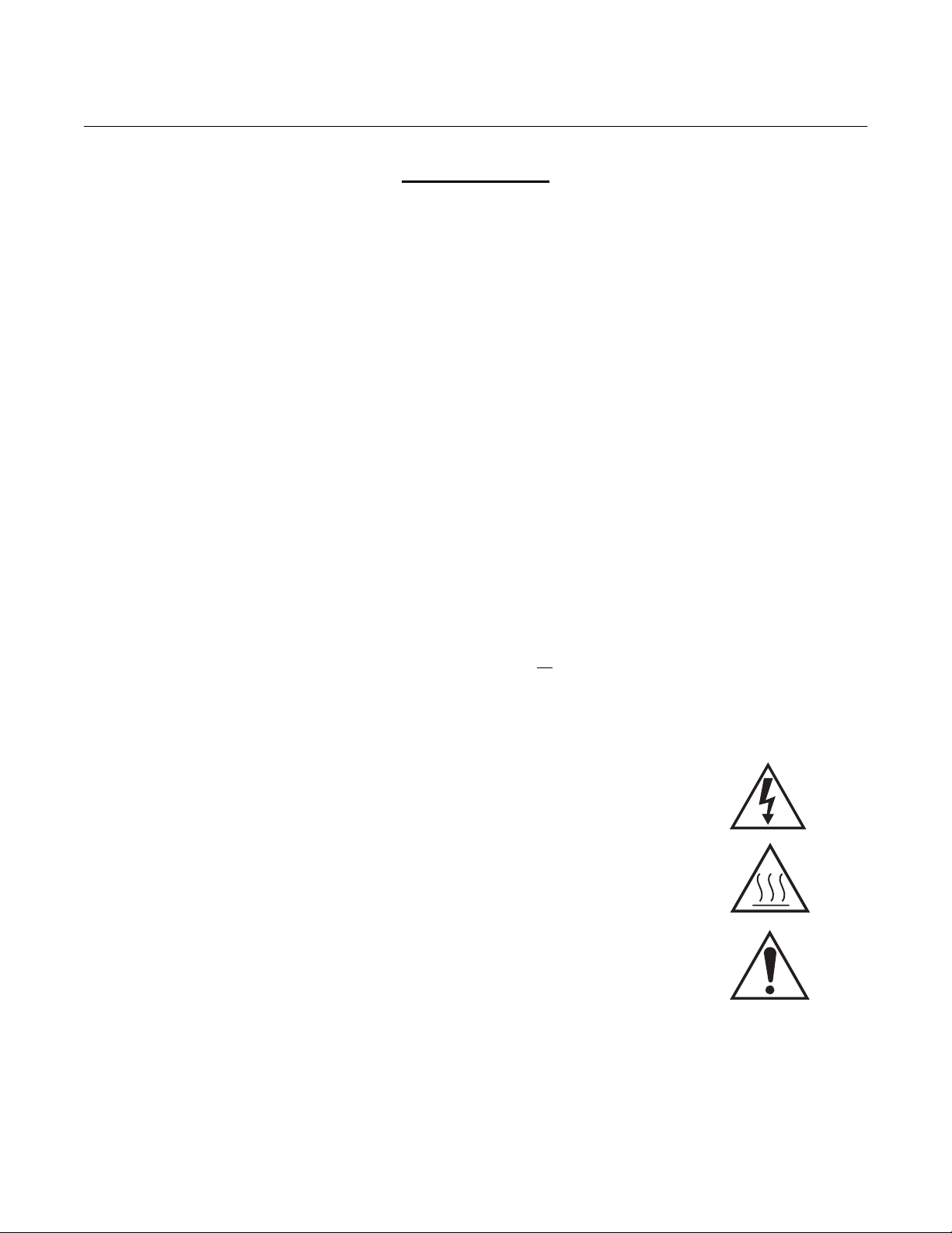
7. Where equipment or covers are marked with the symbol to the right, hazard-
ous voltages are likely to be present beneath. These covers should only be
removed when power is removed from the equipment — and then only by
trained service personnel.
8. Where equipment or covers are marked with the symbol to the right, there is a
danger from hot surfaces beneath. These covers should only be removed by
trained service personnel when power is removed from the equipment. Certain surfaces may remain hot to the touch.
9. Where equipment or covers are marked with the symbol to the right, refer to
the Operator Manual for instructions.
10. All graphical symbols used in this product are from one or more of the follow-
ing standards: EN61010-1, IEC417, and ISO3864.
P-2 Rosemount Analytical Inc. A Division of Emerson Process Management

Hazardous Area Oxymitter DR
CERAMIC FIBER PRODUCTS
MATERIAL SAFETY DATA SHEET
JULY 1, 1996
SECTION I. IDENTIFICATION
PRODUCT NAME
Ceramic Fiber Heaters, Molded Insulation Modules and Ceramic Fiber Radiant Heater Panels.
CHEMICAL FAMILY
Vitreous Aluminosilicate Fibers with Silicon Dioxide.
CHEMICAL NAME
N.A.
Instruction Manual
IB-106-340CDR Original Issue
January, 2002
CHEMICAL FORMULA
N.A.
MANUFACTURER’S NAME AND ADDRESS
Watlow Columbia 573-474-9402
2101 Pennsylvania Drive 573-814-1300, ext. 5170
Columbia, MO 65202
HEALTH HAZARD SUMMARY
WARNING
• Possible cancer hazard based on tests with laboratory animals.
• May be irritating to skin, eyes and respiratory tract.
• May be harmful if inhaled.
• Cristobalite (crystalline silica) formed at high temperatures (above 1800ºF) can cause severe respiratory
disease.
Rosemount Analytical Inc. A Division of Emerson Process Management P-3

Instruction Manual
IB-106-340CDR Original Issue
January, 2002
Hazardous Area Oxymitter DR
SECTION II. PHYSICAL DATA
APPEARANCE AND ODOR
Cream to white colored fiber shapes. With or without optional white to gray granular surface coating and/or optional
black surface coating.
SPECIFIC WEIGHT: 12-25 LB./CUBIC FOOT BOILING POINT: N.A.
VOLATILES (% BY WT.): N.A. WATER SOLUBILITY: N.A.
SECTION III. HAZARDOUS INGREDIENTS
MATERIAL, QUANTITY, AND THRESHOLD/EXPOSURE LIMIT VALUES
Aluminosilicate (vitreous) 99+ % 1 fiber/cc TWA
CAS. No. 142844-00-06 10 fibers/cc CL
Zirconium Silicate 0-10% 5 mg/cubic meter (TLV)
Black Surface Coating** 0 - 1% 5 mg/cubic meter (TLV)
Armorphous Silica/Silicon Dioxide 0-10% 20 mppcf (6 mg/cubic meter)
PEL (OSHA 1978) 3 gm cubic meter
(Respirable dust): 10 mg/cubic meter,
Intended TLV (ACGIH 1984-85)
**Composition is a trade secret.
SECTION IV. FIRE AND EXPLOSION DATA
FLASH POINT: NONE FLAMMABILITY LIMITS: N.A.
EXTINGUISHING MEDIA
Use extinguishing agent suitable for type of surrounding fire.
UNUSUAL FIRE AND EXPLOSION HAZARDS / SPECIAL FIRE FIGHTING PROCEDURES
N.A.
P-4 Rosemount Analytical Inc. A Division of Emerson Process Management

Instruction Manual
IB-106-340CDR Original Issue
Hazardous Area Oxymitter DR
January, 2002
SECTION V. HEALTH HAZARD DATA
THRESHOLD LIMIT VALUE
(See Section III)
EFFECTS OF OVER EXPOSURE
EYE
Avoid contact with eyes. Slightly to moderately irritating. Abrasive action may cause damage to outer surface of eye.
INHALATION
May cause respiratory tract irritation. Repeated or prolonged breathing of particles of respirable size may cause inflammation of the lung leading to chest pain, difficult breathing, coughing and possible fibrotic change in the lung (Pneumoconiosis). Pre-existing medical conditions may be aggravated by exposure: specifically, bronchial hyper-reactivity and
chronic bronchial or lung disease.
INGESTION
May cause gastrointestinal disturbances. Symptoms may include irritation and nausea, vomiting and diarrhea.
SKIN
Slightly to moderate irritating. May cause irritation and inflammation due to mechanical reaction to sharp, broken ends
of fibers.
EXPOSURE TO USED CERAMIC FIBER PRODUCT
Product which has been in service at elevated temperatures (greater than 1800ºF/982ºC) may undergo partial conversion
to cristobalite, a form of crystalline silica which can cause severe respiratory disease (Pneumoconiosis). The amount of
cristobalite present will depend on the temperature and length of time in service. (See Section IX for permissible exposure levels).
SPECIAL TOXIC EFFECTS
The existing toxicology and epidemiology data bases for RCF’s are still preliminary. Information will be updated as
studies are completed and reviewed. The following is a review of the results to date:
EPIDEMIOLOGY
At this time there are no known published reports demonstrating negative health outcomes of workers exposed to refractory ceramic fiber (RCF). Epidemiologic investigations of RCF production workers are ongoing.
1) There is no evidence of any fibrotic lung disease (interstitial fibrosis) whatsoever on x-ray.
2) There is no evidence of any lung disease among those employees exposed to RCF that had never smoked.
3) A statistical “trend” was observed in the exposed population between the duration of exposure to RCF and a de-
crease in some measures of pulmonary function. These observations are clinically insignificant. In other words, if
these observations were made on an individual employee, the results would be interpreted as being within the normal range.
Rosemount Analytical Inc. A Division of Emerson Process Management P-5

Instruction Manual
IB-106-340CDR Original Issue
January, 2002
4) Pleural plaques (thickening along the chest wall) have been observed in a small number of employees who had a
long duration of employment. There are several occupational and non-occupational causes for pleural plaque. It
should be noted that plaques are not “pre-cancer” nor are they associated with any measurable effect on lung
function.
TOXICOLOGY
A number of studies on the health effects of inhalation exposure of rats and hamsters are available. Rats were exposed
to RCF in a series of life-time nose-only inhalation studies. The animals were exposed to 30, 16, 9, and 3 mg/m
corresponds with approximately 200, 150, 75, and 25 fibers/cc.
Animals exposed to 30 and 16 mg/m
posed to 9 mg/m
the response typically observed any time a material is inhaled into the deep lung. While a statistically significant increase in lung tumors was observed following exposure to the highest dose, there was no excess lung cancers at the
other doses. Two rats exposed to 30 mg/m
The International Agency for Research on Cancer (IARC) reviewed the carcinogenicity data on man-made vitreous fibers (including ceramic fiber, glasswool, rockwool, and slagwool) in 1987. IARC classified ceramic fiber, fibrous
glasswool and mineral wool (rockwool and slagwool) as possible human carcinogens (Group 2B).
3
had developed a mild parenchymal fibrosis; animals exposed to the lowest dose were found to have
3
were observed to have developed a pleural and parenchymal fibroses; animals ex-
3
and one rat exposed to 9 mg/m3 developed masotheliomas.
Hazardous Area Oxymitter DR
EMERGENCY FIRST AID PROCEDURES
3
, which
EYE CONTACT
Flush eyes immediately with large amounts of water for approximately 15 minutes. Eye lids should be held away from
the eyeball to insure thorough rinsing. Do not rub eyes. Get medical attention if irritation persists.
INHALATION
Remove person from source of exposure and move to fresh air. Some people may be sensitive to fiber induced irritation
of the respiratory tract. If symptoms such as shortness of breath, coughing, wheezing or chest pain develop, seek medical attention. If person experiences continued breathing difficulties, administer oxygen until medical assistance can be
rendered.
INGESTION
Do not induce vomiting. Get medical attention if irritation persists.
SKIN CONTACT
Do not rub or scratch exposed skin. Wash area of contact thoroughly with soap and water. Using a skin cream or lotion
after washing may be helpful. Get medical attention if irritation persists.
SECTION VI. REACTIVITY DATA
STABILITY/CONDITIONS TO AVOID
Stable under normal conditions of use.
HAZARDOUS POLYMERIZATION/CONDITIONS TO AVOID
N.A.
P-6 Rosemount Analytical Inc. A Division of Emerson Process Management

Instruction Manual
IB-106-340CDR Original Issue
Hazardous Area Oxymitter DR
January, 2002
INCOMPATIBILITY/MATERIALS TO AVOID
Incompatible with hydrofluoric acid and concentrated alkali.
HAZARDOUS DECOMPOSITION PRODUCTS
N.A.
SECTION VII. SPILL OR LEAK PROCEDURES
STEPS TO BE TAKEN IF MATERIAL IS RELEASED OR SPILLED
Where possible, use vacuum suction with HEPA filters to clean up spilled material. Use dust suppressant where sweeping if necessary. Avoid clean up procedure which may result in water pollution. (Observe Special Protection Information Section VIII.)
WASTE DISPOSAL METHODS
The transportation, treatment, and disposal of this waste material must be conducted in compliance with all applicable
Federal, State, and Local regulations.
SECTION VIII. SPECIAL PROTECTION INFORMATION
RESPIRATORY PROTECTION
Use NIOSH or MSHA approved equipment when airborne exposure limits may be exceeded. NIOSH/MSHA approved
breathing equipment may be required for non-routine and emergency use. (See Section IX for suitable equipment).
Pending the results of long term health effects studies, engineering control of airborne fibers to the lowest levels attainable is advised.
VENTILATION
Ventilation should be used whenever possible to control or reduce airborne concentrations of fiber and dust. Carbon
monoxide, carbon dioxide, oxides of nitrogen, reactive hydrocarbons and a small amount of formaldehyde may accompany binder burn-off during first heat. Use adequate ventilation or other precautions to eliminate vapors resulting from
binder burn-off. Exposure to burn-off fumes may cause respiratory tract irritation, bronchial hyper-reactivity and asthmatic response.
SKIN PROTECTION
Wear gloves, hats and full body clothing to prevent skin contact. Use separate lockers for work clothes to prevent fiber
transfer to street clothes. Wash work clothes separately from other clothing and rinse washing machine thoroughly after
use.
EYE PROTECTION
Wear safety glasses or chemical worker’s goggles to prevent eye contact. Do not wear contact lenses when working
with this substance. Have eye baths readily available where eye contact can occur.
Rosemount Analytical Inc. A Division of Emerson Process Management P-7

Instruction Manual
IB-106-340CDR Original Issue
January, 2002
Hazardous Area Oxymitter DR
SECTION IX. SPECIAL PRECAUTIONS
PRECAUTIONS TO BE TAKEN IN HANDLING AND STORING
General cleanliness should be followed.
The Toxicology data indicate that ceramic fiber should be handled with caution. The handling practices described in this
MSDS must be strictly followed. In particular, when handling refractory ceramic fiber in any application, special caution should be taken to avoid unnecessary cutting and tearing of the material to minimize generation of airborne dust.
It is recommended that full body clothing be worn to reduce the potential for skin irritation. Washable or disposable
clothing may be used. Do not take unwashed work clothing home. Work clothes should be washed separately from
other clothing. Rinse washing machine thoroughly after use. If clothing is to be laundered by someone else, inform
launderer of proper procedure. Work clothes and street clothes should be kept separate to prevent contamination.
Product which has been in service at elevated temperatures (greater than 1800ºF/982ºC) may undergo partial conversion
to cristobalite, a form of crystalline silica. This reaction occurs at the furnace lining hot face. As a consequence, this
material becomes more friable; special caution must be taken to minimize generation of airborne dust. The amount of
cristobalite present will depend on the temperature and length in service.
IARC has recently reviewed the animal, human, and other relevant experimental data on silica in order to critically
evaluate and classify the cancer causing potential. Based on its review, IARC classified crystalline silica as a group 2A
carcinogen (probable human carcinogen).
The OSHA permissible exposure limit (PEL for cristobalite is 0.05 mg/m
value (TLV) for cristobalite is 0.05 mg/m
ment when airborne exposure limits may be exceeded. The minimum respiratory protection recommended for given airborne fiber or cristobalite concentrations are:
3
(respirable dust) (ACGIH 1991-92). Use NIOSH or MSHA approved equip-
3
(respirable dust). The ACGIH threshold limit
CONCENTRATION
0-1 fiber/cc or 0-0.05 mg/m3 cristobalite Optional disposable dust respirator (e.g. 3M 9970
(the OSHA PEL) or equivalent).
Up to 5 fibers/cc or up to 10 times the Half face, air-purifying respirator equipped with high
OSHA PEL for cristobalite efficiency particulate air (HEPA) filter cartridges
(e.g. 3M 6000 series with 2040 filter or equivalent).
Up to 25 fibers/cc or 50 times the OSHA Full face, air-purifying respirator with high efficiency
PEL for cristobalite (2.5 mg/m
Greater than 25 fibers/cc or 50 times the Full face, positive pressure supplied air respirator
OSHA PEL for cristobalite (2.5 mg/m
If airborne fiber or cristobalite concentrations are not known, as minimum protection, use NIOSH/MSHA approved half
face, air-purifying respirator with HEPA filter cartridges.
3
) particulate air (HEPA) filter cartridges (e.g. 3M 7800S
with 7255 filters or equivalent) or powered air -purifying
respirator (PARR) equipped with HEPA filter cartridges
(e.g. 3M W3265S with W3267 filters or equivalent).
3
) (e.g. 3M 7800S with W9435 hose & W3196 low
pressure regulator kit connected to clean air supply
or equivalent).
P-8 Rosemount Analytical Inc. A Division of Emerson Process Management

Instruction Manual
IB-106-340CDR Original Issue
Hazardous Area Oxymitter DR
Insulation surface should be lightly sprayed with water before removal to suppress airborne dust. As water evaporates
during removal, additional water should be sprayed on surfaces as needed. Only enough water should be sprayed to
suppress dust so that water does not run onto the floor of the work area. To aid the wetting process, a surfactant can be
used.
After RCF removal is completed, dust-suppressing cleaning methods, such as wet sweeping or vacuuming, should be
used to clean the work area. If dry vacuuming is used, the vacuum must be equipped with HEPA filter. Air blowing or
dry sweeping should not be used. Dust-suppressing components can be used to clean up light dust.
Product packaging may contain product residue. Do not reuse except to reship or return Ceramic Fiber products to the
factory.
January, 2002
Rosemount Analytical Inc. A Division of Emerson Process Management P-9

Instruction Manual
IB-106-340CDR Original Issue
January, 2002
For assistance with technical problems, please call the Customer Support Center (CSC). The
CSC is staffed 24 hours a day, 7 days a week.
In addition to the CSC, you may also contact Field Watch. Field Watch coordinates Rosemount’s
field service throughout the U.S. and abroad.
Rosemount may also be reached via the Internet through e-mail and the World Wide Web:
Hazardous Area Oxymitter DR
Technical Support Hotline:
Phone: 1-800-433-6076
Phone: 1-800-654-RSMT (1-800-654-7768)
e-mail: GAS.CSC@frco.com
World Wide Web: www.processanalytic.com
P-10 Rosemount Analytical Inc. A Division of Emerson Process Management

Hazardous Area Oxymitter DR
1
DESCRIPTION AND SPECIFICATIONS
Instruction Manual
IB-106-340CDR Original Issue
January, 2002
SECTION 1
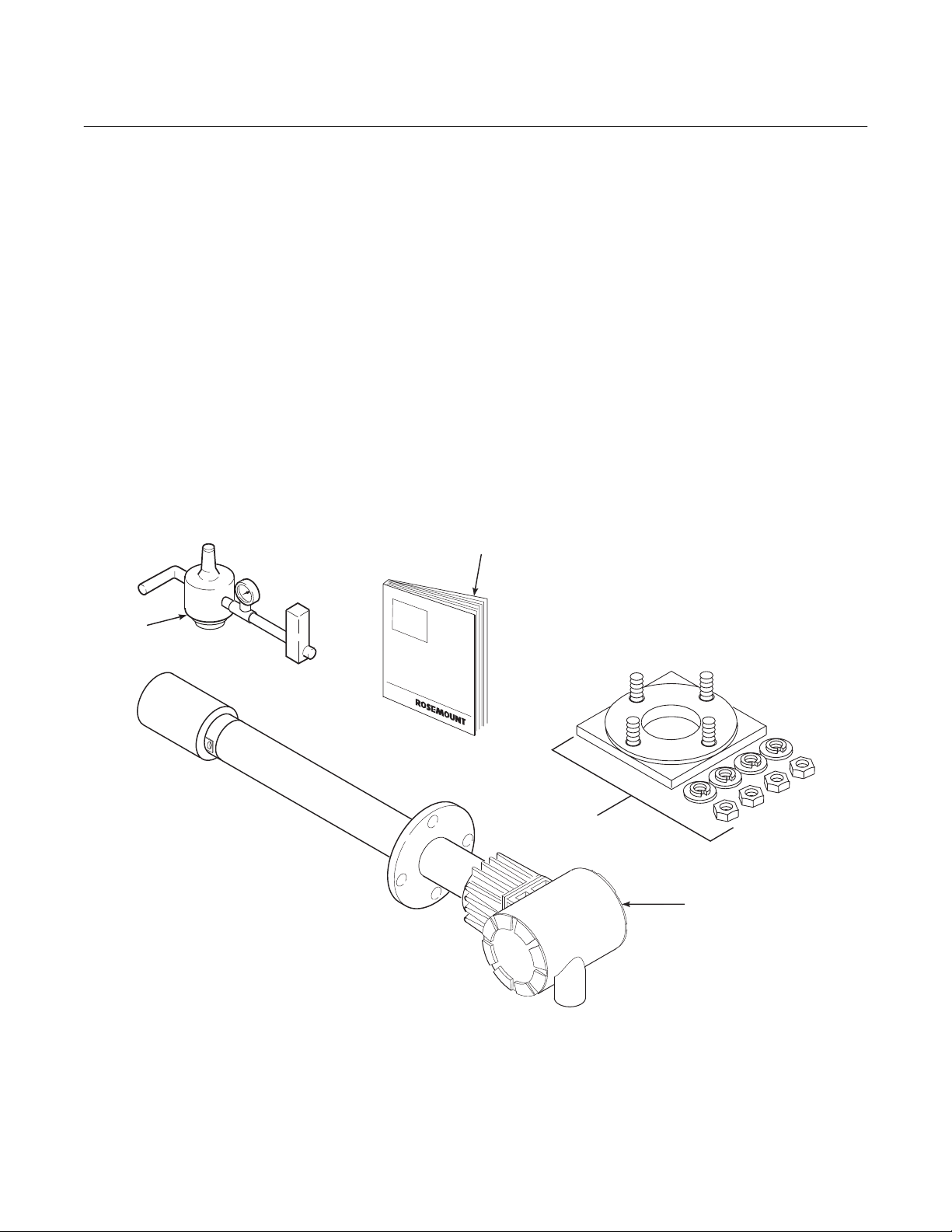
1-1 COMPONENT CHECKLIST OF TYPICAL
SYSTEM (PACKAGE CONTENTS)
A typical Rosemount Hazardous Area Oxymitter
DR In-Situ Oxygen Probe should contain the
items shown in Figure 1-1. Record the part number, serial number, and order number for each
component of your system in the table located on
the back cover of this manual.
The Oxymitter DR is offered in both
hazardous and general purpose configurations. The hazardous area version has the “EX” and CSA symbols
on the apparatus approval label. The
general purpose version does not
have an approval label. If you received
the general purpose version, ensure
you do not install it in a potentially explosive atmosphere.
Also, use the product matrix in Table 1-1 at the
end of this section to compare your order number against your unit. The first part of the matrix
defines the model. The last part defines the
various options and features of the Hazardous
Area Oxymitter DR. Ensure the features and
options specified by your order number are on
or included with the unit.
b. System Description
The Hazardous Area Oxymitter DR is designed to measure the net concentration of
oxygen in an industrial combustion process;
i.e., the oxygen remaining after all fuels have
been oxidized. The probe is permanently positioned within an exhaust duct or stack and
performs its task without the use of a sampling system.
The equipment measures oxygen percentage by reading the voltage developed across
a heated electrochemical cell, which consists
of a small yttria-stabilized, zirconia disc. Both
sides of the disc are coated with porous
metal electrodes. When operated at the
proper temperature, the millivolt output voltage of the cell is given by the following
Nernst equation:
EMF = KT log
Where:
1. P
is the partial pressure of the
2
oxygen in the measured gas on
one side of the cell.
2. P
is the partial pressure of the
1
oxygen in the reference air on
the opposite side of the cell.
3. T is the absolute temperature.
10(P1/P2
) + C
1-2 SYSTEM OVERVIEW
a. Scope
This Instruction Bulletin is designed to supply
details needed to install, start up, operate,
and maintain the Hazardous Area Oxymitter
DR. The Hazardous Area Direct Replacement Oxymitter can be interfaced to a number of different earlier model electronics
packages. These electronic packages are
not covered in this manual. For specification
information concerning calibration and operation of the system, refer to the Instruction
Bulletin applicable to your electronics.
Rosemount Analytical Inc. A Division of Emerson Process Management Description and Specifications 1-1
4. C is the cell constant.
5. K is an arithmetic constant.
When the cell is at operating temperature
and there are unequal oxygen concentrations across the cell, oxygen ions will travel
from the high oxygen partial pressure side to
the low oxygen partial pressure side of the
cell. The resulting logarithmic output voltage
is approximately 50 mV per decade. The
output is proportional to the inverse logarithm
of the oxygen concentration. Therefore, the
output signal increases as the oxygen concentration of the sample gas decreases. This
characteristic enables the Hazardous Area
Oxymitter DR to provide exceptional sensitivity at low oxygen concentrations.
Instruction Manual
IB-106-340CDR Original Issue
January, 2002
Hazardous Area Oxymitter DR
The Hazardous Area Oxymitter DR measures net oxygen concentration in the presence of all the products of combustion,
including water vapor. Therefore, it may be
considered an analysis on a “wet” basis. In
comparison with older methods, such as the
portable apparatus, which provides an
analysis on a “dry” gas basis, the “wet”
analysis will, in general, indicate a lower percentage of oxygen. The difference will be
proportional to the water content of the sampled gas stream.
c. System Configuration
Hazardous Area Oxymitter DR units are
available in three length options, giving the
user the flexibility to use an in situ penetration appropriate to the size of the stack or
duct. The options on length are 457 mm
(18 in.), 0.91 m (3 ft), 1.83 m (6 ft).
Abrasive shields are offered for applications
where abrasive particulates are present.
Acid resistant cells are available for SO
2
and HCl environments. Bypass and probe
mounting jacket options are available for
process temperatures above 1300°F
(705°C).
d. System Features
1. The cell output voltage and sensitivity
increase as the oxygen concentration
decreases.
2. Field replaceable cell, heater, thermocouple, and diffusion element.
3. The Hazardous Area Oxymitter DR is
constructed of rugged 316L stainless
steel for all wetted parts.
1
4
2
3
1. Instruction Bulletin
2. Adapter Plate with Mounting Hardware and Gasket
3. Hazardous Area Oxymitter DR
4. Reference Air Set
36220001
Figure 1-1. Typical System Package
1-2 Description and Specifications Rosemount Analytical Inc. A Division of Emerson Process Management
Hazardous Area Oxymitter DR
1
Instruction Manual
IB-106-340CDR Original Issue
January, 2002
e. Handling the Hazardous Area
Oxymitter DR
The Hazardous Area Oxymitter DR is
designed for industrial applications.
Treat each component of the system
with care to avoid physical damage.
Some probe components are made
from ceramics, which are susceptible
to shock when mishandled.
f. System Considerations
Prior to installing your Hazardous Area
Oxymitter DR, make sure you have all the
components necessary to make the system
installation. Ensure all the components are
properly integrated to make the system
functional.
NOTE
Retain the packaging in which the
Hazardous Area Oxymitter DR arrived
from the factory in case any components are to be shipped to another
site. This packaging has been designed to protect the product.
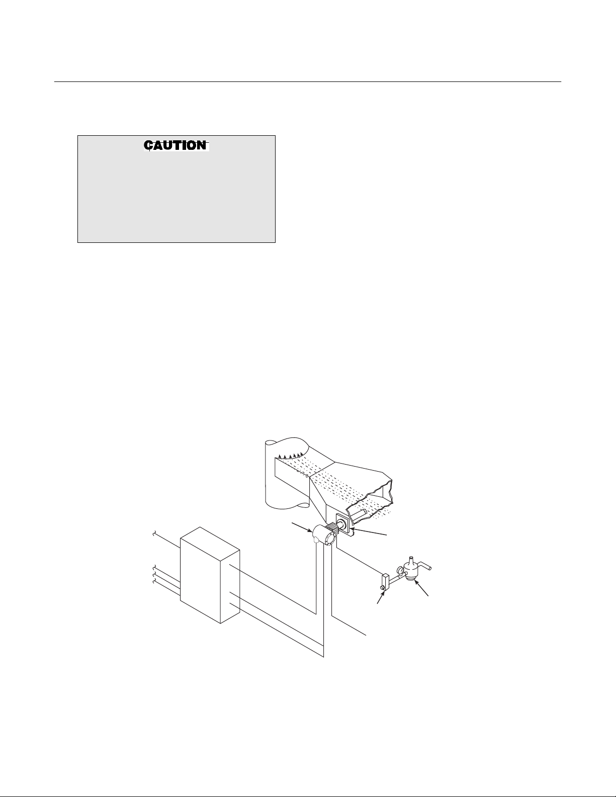
After verifying that you have all the components, select mounting locations and determine how each component will be placed in
terms of available line voltage, ambient
temperatures, environmental considerations, convenience, and serviceability. A
typical system installation is illustrated in
Figure 1-2.
Instrument air for reference is optional for
most applications. Ambient air will passively
diffuse into the inside of the probe in sufficient quantity for an accurate measurement.
Instrument air is required for applications
where the ambient air at the probe location
may not contain the typical 20.95% O
example would be an installation into a
positive pressure flue gas duct which has
many leaks into the surrounding air.
If the calibration gas bottles will be permanently connected, a blocking valve or check
valve is required next to the calibration fittings on the termination housing.
. An
2
4-20 mA
SIGNAL
AC POWER
OXYMITTER DR
EXISTING SIGNAL
CONDITIONING
ELECTRONICS
Figure 1-2. Typical System Installation
GASES
STACK
HEATER
POWER
OXYGEN
SIGNAL
THERMOCOUPLE
SIGNAL
DUCT
FLOWMETER
CALIBRATION
GAS
ADAPTER
PLATE
PRESSURE
REGULATOR
INSTRUMENT
AIR SUPPLY
(REFERENCE AIR)
36210004
Rosemount Analytical Inc. A Division of Emerson Process Management Description and Specifications 1-3
Instruction Manual
IB-106-340CDR Original Issue
January, 2002
This check valve or blocking valve is to
prevent breathing of the calibration gas line
and subsequent flue gas condensation and
corrosion.
g. Upgrading the Hazardous Area
Oxymitter DR
The Hazardous Area Oxymitter DR can
be easily upgraded to a full Oxymitter
4000 or 5000. This provides an economical upgrade path for users looking to preserve their probe investment upon the
eventual failure of the signal conditioning
electronics. Upgrading the Hazardous
Area Oxymitter DR to a full Oxymitter
4000 or 5000 requires only the addition of
a small electronics package to the existing termination housing of the Hazardous
Area Oxymitter DR probe. The converted
unit will be a full Oxymitter 4000 or 5000
Oxygen Transmitter with the capability of
providing a 4-20 mA oxygen signal without the need for an external signal conditioning electronics package. HART or
Fieldbus communications are provided
with the Oxymitter electronics. See Appendix A for upgrade information.
1-3 PROBE OPTIONS
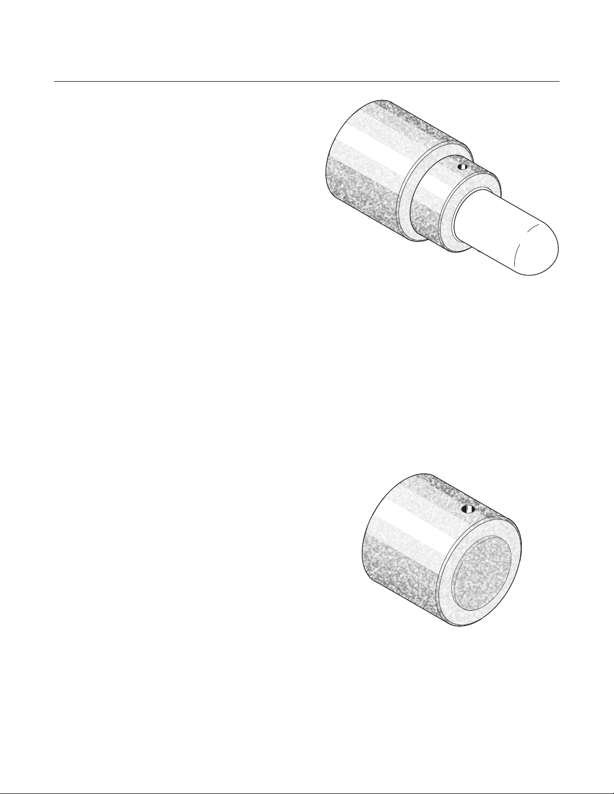
a. Abrasive Shield Assembly
Hazardous Area Oxymitter DR
36220005
Figure 1-3. Flame Arrestor Diffusion Assembly
tures from igniting unburned fuel in the
stack. The ceramic diffusion assembly is
also available with a dust seal for use with
the abrasive shield assembly.
c. Flame Arrestor Snubber Diffusion
Assembly
The snubber diffusion assembly, Figure 14, is satisfactory for most applications.
This element is also available with a dust
seal for use with an abrasive shield.
The abrasive shield assembly, Figure 1-5,
is a stainless-steel tube that surrounds
the probe assembly. The shield protects
against particle abrasion and condensations, provides a guide for ease of
insertion, and acts as a position support,
especially for longer probes. The abrasive
shield assembly uses a modified diffusor
and vee deflector assembly, fitted with
dual dust seal packing.
b. Flame Arrestor Ceramic Diffusion
Assembly
The flame arrestor ceramic diffusion assembly, Figure 1-3, includes a set of baffles between the cell and the stack gases.
This keeps 816°C (1500°F) cell tempera-
1-4 Description and Specifications Rosemount Analytical Inc. A Division of Emerson Process Management
Figure 1-4. Flame Arrestor Snubber Diffusion
Assembly
36220006
Hazardous Area Oxymitter DR
1
Instruction Manual
IB-106-340CDR Original Issue
January, 2002
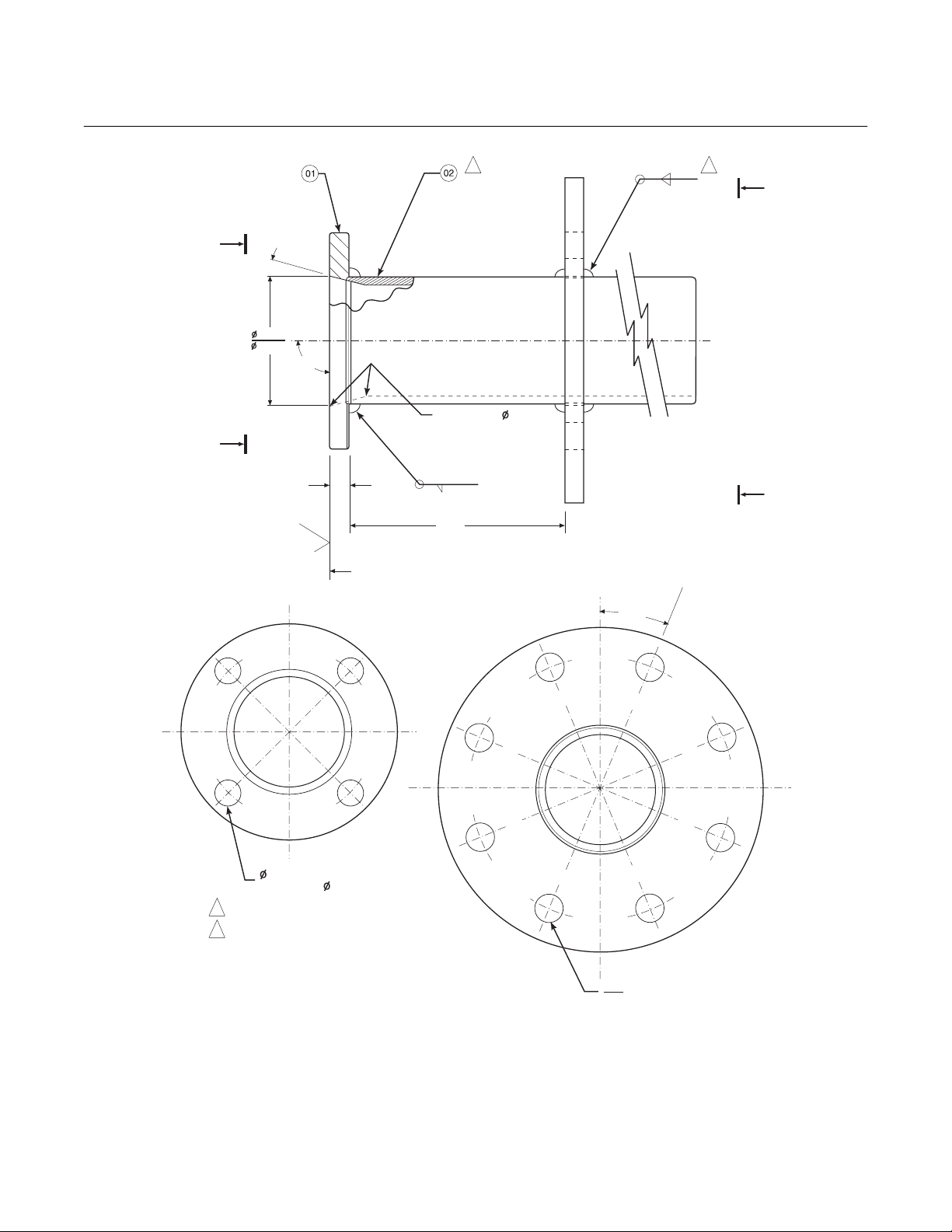
2
.187
.187
1
B
A
o
15
3.584
3.554
A
.45 MIN
VIEW A
o
90
ON INSIDE BREAK
FOR SMOOTH
ROUNDED EDGE ON
BOTH ENDS
OF CHAMFER
125
.187
6.00
SKIN CUT FACE FOR 90
o
B
VIEW B
o
22.5
0.75 THRU 4 PLS,
EQ SP ON 4.75 B.C.
NOTES:
16860033
1 WELD ON BOTH SIDES WITH EXPANDING
CHILL BLOCK.
2 BEFORE WELDING, BUTT ITEM 2 OR 4 WITH
ITEM 1 AS SHOWN.
.745
DIA ON A 7.50 DIA B.C. (REF)
.755
Figure 1-5. Abrasive Shield Assembly
NOTE
In highly abrasive applications, rotate the shield 90 degrees at normal
service intervals to present a new wear surface to the abrasive flow stream.
Rosemount Analytical Inc. A Division of Emerson Process Management Description and Specifications 1-5

Instruction Manual
IB-106-340CDR Original Issue
January, 2002
1-4 SPECIFICATIONS
Hazardous Area Certifications ............................ CENELEC EEXd IIB + H2 T3
Probe Lengths .................................................... 18 in. (457 mm)
Temperature Limits in Process
Measurement Area .................................. 0° to 704°C (32° to 1300°F)
Hazardous Area Oxymitter DR
CSA Class I, Division 1, Groups B, C, D
3 ft (0.91 m)
6 ft (1.83 m)
up to 1300°C (2400°F) with optional accessories
Resolution Sensitivity ......................................... 0.01% O
Sensing Cell Repeatability ................................. ±0.75% of O
transmitted signal
2
reading, or 0.05% O
2
2
System Response to Calibration Gas ................ Initial response in less than 3 seconds T90 in less than
8 seconds
Resolution Sensitivity ......................................... 0.01% of O
value
2
Mounting and Mounting Position ........................ Vertical or horizontal
Materials:
Probe ....................................................... Wetted or welded parts - 316L stainless steel
Non-wetted parts - 304 stainless steel, low-copper
aluminum
Termination Housing ............................... Low-copper aluminum
Calibration Gas Mixtures Recommended .......... 0.4% O
8% O2, Balance N
, Balance N
2
2
2
Calibration Gas Flow .......................................... 2.5 l/m (5 scfh)
Optional Reference Air ....................................... 1 l/m (2 scfh), clean, dry, instrument-quality air
(20.95% O
), regulated to 34 kPa (5 psi), Optional
2
Heater Voltage ................................................... 115 ±10% VAC, 50/60 Hz., 200VA
Thermocouple .................................................... Type K
Power Requirements:
Nominal ................................................... 175 W
Maximum ................................................. 500 W
Ambient Operating Temperature
(Junction Box) .......................................... 93°C (200°F) [71°C (160°F) max
for YEW replacement]
Fisher-Rosemount has satisfied all obligations coming from the European legislation to harmonize
the product requirements in Europe.
1-6 Description and Specifications Rosemount Analytical Inc. A Division of Emerson Process Management
Loading...