


READ AND SAVE THESE INSTRUCTIONS
HIGHPOINT™
54” Ceiling Fan Owner's Manual
CF205BS01 - Model Numbers
Brushed Steel Housing, Dark Mahogany Finish Blades & Opal Matte Glass
CF205GES01 - Golden Espresso Housing, Chocolate
Finish Blades & Sandstone Glass
CF205GRT01 - Graphite Housing, Charcoal/Timber
Gray Blades & Opal Matte Glass
CF205VS01 - Vintage Steel Housing, River Wash/ Honey Oak Dual Finish Blades & Vintage Cream Glass
Net Weight: 22.4 Lbs.
Questions, problems, missing parts: Before returning to the store call Emerson Electric Customer Service 8 a.m. - 6 p.m., Eastern, Monday-Friday
Part No. F40BP73750003
Revision: 161201
1-800-654-3545
www.emersonfans.com
Section |
Page |
Section |
Page |
|
Safety Instructions . . . . . . . . . . . . . . . . . . . . . . . . . . . . . . . . |
. . . . 2 |
9. Remote Control Procedures . . . . . . . . . . . . . . . . . . . . . . |
.22-24 |
|
1. Unpacking Instructions . . . . . . . . . . . . . . . . . . . . . . . . . . . |
. . 3-4 |
10. Reverse Switch Operation . . . . . . . . . . . . . . . . . . . . . . . |
. . . 25 |
|
2. |
Electrical Requirements . . . . . . . . . . . . . . . . . . . . . . . . . . |
. . . 4 |
11. Accessories . . . . . . . . . . . . . . . . . . . . . . . . . . . . . . . . . . . |
. . 25 |
3. Ceiling Fan Assembly . . . . . . . . . . . . . . . . . . . . . . . . . . . . |
5-10 |
12. Repair Parts . . . . . . . . . . . . . . . . . . . . . . . . . . . . . . . . . . |
26-27 |
|
4. How to Hang Your Ceiling Fan . . . . . . . . . . . . . . . . . . . . |
11-12 |
13. Maintenance . . . . . . . . . . . . . . . . . . . . . . . . . . . . . . . . . . |
. . .28 |
|
5. How to Wire Your Ceiling Fan . . . . . . . . . . . . . . . . . . . . . |
13-17 |
14. Troubleshooting . . . . . . . . . . . . . . . . . . . . . . . . . . . . . . . . |
. . 28 |
|
6. |
Ceiling Cover Installation . . . . . . . . . . . . . . . . . . . . . . . . . |
. . 18 |
Ceiling Fan Limited Warranty . . . . . . . . . . . . . . . . . . . . . . . . |
. . .29 |
7. |
Final Installation . . . . . . . . . . . . . . . . . . . . . . . . . . . . . . . . . |
. . 19 |
Spanish . . . . . . . . . . . . . . . . . . . . . . . . . . . . . . . . . . . . . . . . . |
. . .31 |
8. Disassemble Your Light Kit for |
20-21 |
French . . . . . . . . . . . . . . . . . . . . . . . . . . . . . . . . . . . . . . . . . . |
. . .61 |
|
|
Cover Plate Assembly Only . . . . . . . . . . . . . . . . . . . . . . . |
|
|
|
|
|
|
||
|
READ AND SAVE THESE INSTRUCTIONS |
|
||
! WARNING
TO REDUCE THE RISK OF FIRE, ELECTRICAL SHOCK, OR INJURY TO PERSONS, OBSERVE THE FOLLOWING: a. Use this unit only in a manner intended by the manufacturer. If you have questions, contact the
manufacturer.
b. Before servicing or cleaning unit, switch power off at service panel and lock service panel disconnecting means to prevent power from being switched on accidentally. When the service disconnecting means cannot be locked, securely fasten a warning device, such as a tag, to the service panel.
1. Read your owner’s manual carefully and keep it for future reference.
2. Be careful of the fan and blades when cleaning, painting, or working near the fan. Always turn off the power to the ceiling fan before servicing.
3. Do not put anything into the fan blades while they are turning.
4. Do not operate reversing switch until fan blades have come to a complete stop.
Additional Safety Instructions for Installation
1. To avoid possible shock, be sure electricity is turned off at the fuse box before wiring, and do not operate fan without blades.
2. All wiring must be in accordance with the National Electrical Code “ANSI/NFPA 70-2014” and Local Electrical Codes. Use the National Electrical Code if Local Codes do not exist. The ceiling fan must be grounded as a precaution against possible electrical shock. Electrical installation should be made or approved by a licensed electrician.
3. The outlet box and joist must be securely mounted and capable of reliably supporting at least 50 pounds. Use only U.L. outlet boxes listed as “Acceptable for Fan Support of 22.7kg. (50 lbs.) or less”, and use the mounting screws provided with the outlet box. Most outlet boxes commonly used for support of light fixtures are not acceptable for fan support and may need to be replaced. Consult a qualified electrician if in doubt.
|
4. The longer downrod furnished with the fan provides the |
||
|
minimum recommended floor to fan blade clearance for a |
||
|
9 foot ceiling. The 6” downrod (supplied) must be used |
||
|
for an 8 foot ceiling. |
|
|
|
5. The fan must be mounted with the fan blades at least |
||
|
7 feet from the floor to prevent accidental contact with |
||
|
the fan blades. |
|
|
|
6. Follow the recommended instructions for the proper |
||
|
method of wiring your ceiling fan. If you do not know |
||
|
enough about electrical wiring, have your fan installed by |
||
|
a licensed electrician. |
|
|
|
CAUTION: The halogen bulbs operate at high internal |
||
|
pressure and high surface temperatures and could shatter |
||
|
unexpectedly. The halogen bulbs generate UV |
||
|
(ultraviolet) radiation that may cause skin and eye irritation |
||
|
with prolonged exposure. To avoid risks of burns or other |
||
|
injury, assure power is off before attempting to install or |
||
|
replace halogen bulb. Do not operate fan/light without lower |
||
|
glass in place. |
|
|
|
7. This fan uses halogen bulbs. Do not touch the bulb with |
||
|
bare hands. Fingerprints may result in shorter bulb life. |
||
|
Remove fingerprints with alcohol. |
||
|
NOTE: |
This fan is suitable for use with solid-state speed |
|
|
controls. |
All setscrews must be checked and re-tightened |
|
|
NOTE: |
||
|
where necessary before installation. |
||
|
|
|
|
|
|
! |
WARNING |
|
|
|
|
|
To reduce the risk of electrical shock, this fan must be |
||
|
installed with an isolating wall control/switch. |
||
|
To reduce the risk of fire or electrical shock, this fan |
||
|
should only be used with fan speed control, Model No. |
||
|
UC7067RA, manufactured by Rhine Electric Co., Ltd. |
||
|
To avoid fire, shock or injury, do not use an Emerson or |
||
|
any other brand of control not specifically approved for |
||
|
this fan. |
|
|
|
This product is designed to use only those parts supplied |
||
|
with this product and/or any accessories designated |
||
|
specifically for use this product by Emerson Electric Co. |
||
|
Substitution of parts or accessories not designated for |
||
|
use with this product by Emerson could result in |
||
|
personal injury or property damage. |
||
|
To reduce the risk of personal injury, do not bend the |
||
|
blade flange when installing the blade flanges, balancing |
||
|
the blades or cleaning the fan. Do not insert foreign |
||
|
objects in between rotating fan blades. |
||
2 |
|
|
|
|
|
U.L. Model No.: CF205 |
|

1. Unpacking Instructions
|
|
|
|
|
|
|
! |
WARNING |
|
|
|
|
|
|
|
Do not install or use fan if any part is damaged or |
|||
|
missing. Call Toll-Free: |
|
|
|
|
|
1-800-654-3545 |
|
|
|
|
|
|
|
|
|
|
|
|
|
|
! |
WARNING |
|
|
|
|
|
|
|
This product is designed to use only those parts supplied |
|||
|
with this product and/or any accessories designated |
|||
|
specifically for use with this product by Emerson Electric |
|||
|
Co. Substitution of parts or accessories not designated |
|||
|
for use with this product by Emerson Electric Co. could |
|||
|
result in personal injury or property damage. |
|
||
|
|
|
|
|
|
|
|
|
|
1.1 |
|
|
|
|
|
Check to see that you have received the following parts: |
|||
|
NOTE: If you are uncertain of part description, refer to |
|||
|
exploded view illustration. |
|
||
|
HARDWARE CONTENTS |
|
||
|
|
|
|
|
|
1 |
Threaded Studs, #8-32 x 1-1/4” |
2 |
|
|
Part |
Description |
Qty. |
|
|
|
|
|
|
|
2 |
Knurled Knobs, #8-32 |
2 |
|
|
3 |
Lockwashers, External Tooth, #8 |
2 |
|
|
4 |
Wire Connectors |
|
7 |
|
5 |
Clevis Pin |
|
1 |
|
6 |
Hairpin Clip |
|
1 |
|
7 |
1/4-20 x 11mm Pan Head Screws |
7 |
|
|
8 |
10-24 x 9 mm Oval Head Screws |
10 |
|
|
9 |
#8-32 x 10 mm Pan Head Screw w/Lockwashes |
1 (spare) |
|
|
10 |
Blade Balance Kit |
|
1 |
|
2 |
4 |
1 |
3 |
|
|
5 |
8 |
|
|
|
6 |
|
|
|
|
9 |
|
7 |
10 |
|
|
PACKAGE CONTENTS
A |
Fan Motor/Housing Assembly |
1 |
Part |
Description |
Quantity |
B |
Ceiling Cover |
1 |
C |
Motor Coupler Cover |
1 |
D |
Fan Blades |
3 |
E |
Fan Blades Flanges |
3 |
F |
Decorative Blade Nuts (bagged) |
9 |
G |
Hanger Bracket |
1 |
H |
Hanger Ball/12” Downrod Assembly |
1 |
I |
6” Downrod |
1 |
J |
Rod Support Assembly |
3 |
K |
Decorative Rod Assembly |
3 |
L |
Decorative Rod Assembly Screw (bagged) |
6 |
M |
Light Kit Plate |
1 |
N |
Lower Glass |
1 |
O |
Cover Plate |
1 |
P |
50-Watt Mini-Candelabra Base Halogen Bulb |
2 |
Q |
Remote Control Transmitter, SR401 |
1 |
R |
Remote Control Receiver |
1 |
|
|
H |
|
|
|
I |
|
A |
|
J |
|
|
|
||
B |
|
K |
|
|
|
||
C |
|
L |
|
|
D |
|
|
|
|
P |
|
E |
M |
|
|
|
|
||
F |
|
Q |
|
N |
|
||
G |
R |
||
|
|||
|
|
||
|
O |
|
NOTE: The loose parts are individually packaged for ease of installation. Place the parts from the loose parts bags in a small container to keep them from being lost. If any parts are missing, contact your local retailer or catalog outlet for replacement before proceeding.
1.2
Remove the fan assembly from the protective plastic bag. Place the fan assembly into the upper foam pad with the bottom of the motor facing up.
The upper foam pad serves as a holder for the fan during the first stages of assembly.
emersonfans.com 3 Please contact 1-800-654-3545 for further assistance U.L. Model No.: CF205
(Continued)
|
|
|
|||||
|
|
|
|
|
|
|
|
|
This Manual Is Designed to Make it as Easy as Possible for You to Assemble, |
||||||
|
|
Install, Operate and Maintain Your Ceiling Fan |
|||||
|
|
|
Your Emerson ceiling fan comes supplied with a Fan/Light |
||||
|
Tools Needed for Assembly |
||||||
|
One Phillips head screwdriver |
|
One stepladder |
|
Remote Control which consists of a receiver mounted |
||
|
|
|
inside the ceiling cover of the fan motor housing. This |
||||
|
One wire stripper |
|
|
One wire cutter |
|
system allows you to regulate your ceiling fan speed and |
|
|
|
Materials |
|
|
light ON/OFF. |
||
|
|
|
|
|
|
||
|
Wiring outlet box and box connectors must be of type |
|
NOTE: An optional Emerson Electric SW406 Wall |
|
|||
|
required by the local code. The minimum wire would be a |
|
Control may also be used to control your ceiling fan. |
|
|||
|
3-conductor (2-wire with ground) of following size: |
|
|
|
|||
|
|
|
|
||||
|
Installed Wire Length |
Wire Size A.W.G. |
|
! WARNING |
|
||
|
|
|
|
||||
|
Up to 50 ft. |
|
|
14 |
|
Before assembling your ceiling fan, refer to section on |
|
|
50-100 ft. |
|
|
12 |
|
proper method of wiring your fan (page 13). If you feel |
|
|
|
|
|
|
|
you do not have enough wiring knowledge or experience, |
|
|
|
|
|
|
|
|
|
|
|
|
|
|
|
have your fan installed by a licensed electrician. |
|
|
|
|
|
|
|
|
|
|
|
|
|
|
|
|
|
Your new ceiling fan will require a grounded electrical supply line of 120 volts AC, 60 Hz, 15 amp circuit.
The outlet box must be securely anchored and capable of withstanding a load of at least 50 pounds.
! WARNING
To reduce the risk of fire, electric shock, or personal injury, mount fan to outlet box marked “Acceptable for Fan Support of 22.7kg. (50 lbs.) or less”, and use screws supplied with outlet box. Most outlet boxes commonly used for support of light fixtures are not acceptable for fan support and may need to be replaced. Consult a qualified electrician if in doubt.
! WARNING
Turning off wall switch is not sufficient. To avoid possible electrical shock, be sure electricity is turned off at the main fuse box before wiring. All wiring must be in accordance with National and Local codes and the ceiling fan must be properly grounded as a precaution against possible electrical shock.
4 |
U.L. Model No.: CF205 |
3.1 |
|
|
|
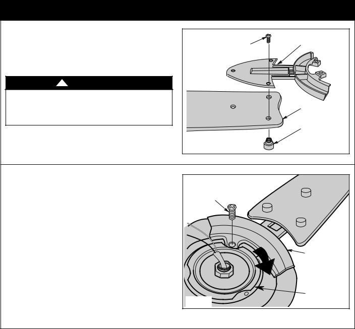
Mount the fan blades to the blade flanges using three |
10-24 x 9mm OVAL |
BLADE FLANGE |
|
10-24 x 9mm oval head screws and three decorative blade |
HEAD SCREW (3) |
|
|
nuts (supplied) (Figure 1). |
|
|
|
! |
WARNING |
|
|
To reduce the risk of personal injury, do not bend the |
|
|
|
blade flange when installing the blade flanges, |
|
|
|
balancing the blades or cleaning the fan. Do not insert |
|
FAN BLADE |
|
foreign objects in between rotating fan blades. |
|
|
|
|
|
|
DECORATIVE |
|
|
|
BLADE NUTS (3) |
|
|
Figure 1 |
|
3.2 |
|
1/4-20 x 11mm PAN HEAD |
|
Remove and discard the three shipping retainers securing |
|
||
the motor hub in the motor housing. |
SCREW (2 per flange) |
|
|
|
|
|
|
NOTE: Take care not to scratch the fan housing when |
|
|
|
installing the blade assemblies. |
|
|
|
Rotate the motor hub to position the slot in the motor plate |
|
|
|
over the fan motor/housing flange hole. |
|
|
|
Attach the blade flange assembly on the fan motor/ |
|
BLADE FLANGE |
|
housing by slowly rotating the motor hub to align screw |
|
|
|
holes. Tighten the 1/4-20 x 11mm pan head screws |
|
|
|
securely while interlocking the flange assemblies as you |
|
|
|
rotate the hub (Figure 2). |
|
|
|
|
|
Figure 2 |
MOTOR HUB |
|
|
|
|
emersonfans.com 5 Please contact 1-800-654-3545 for further assistance U.L. Model No.: CF205
|
(Continued) |
|
3.3 |
|
|
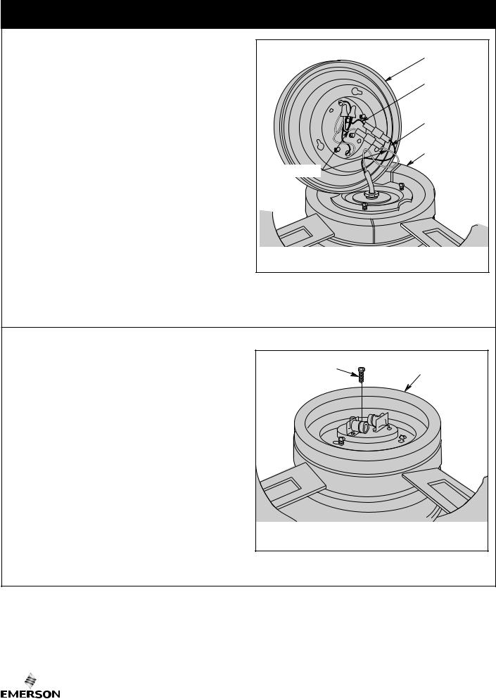
Your ceiling fan can be assembled with the light kit |
|
PLATE |
and glass or without the light kit and glass. |
|
LIGHT KIT |
|
|
|
To assemble without the light kit and glass, you will |
|
BLACK WIRE |
use the no-light cover plate. In order to use the |
|
|
no-light cover plate, the light sockets will need to be |
|
|
removed from the light kit plate. |
|
BLUE WIRE |
NOTE: In order to remove the light sockets, the wires |
|
|
on the light kit plate will need to be cut. MAKE SURE |
|
FAN MOTOR/ |
THIS IS THE NO LIGHT ASSEMBLY DESIRED. |
|
HOUSING |
NOTE: If no light kit is to be used on the ceiling fan, |
WHITE WIRES |
ASSEMBLY |
disregard Steps 3.3 and 3.4; proceed to “How to |
|
|
Disassemble Your Light Kit for Cover Plate Assembly |
|
|
Only”, then continue to Step 3.5. |
|
|
Connect the white wire from the light kit plate to the white |
|
|
wire in the fan motor/ housing assembly (Figure 3). |
|
|
Connect the black wire from the light kit plate to the black |
|
|
wire in the fan motor/housing assembly. |
Figure 3 |
|
CAUTION: Before installing and tightening the |
|
|
screws, be sure there are no wires pinched between |
|
|
the light kit plate and the fan motor/housing |
|
|
assembly. |
|
|
3.4 |
MOTOR SCREW (3) |
LIGHT KIT PLATE |
Remove one of the fan motor/housing assembly screw |
||
|
|
|
(retain for later use). Position the light kit plate on the fan |
|
|
motor/housing assembly aligning the keyhole slots over |
|
|
the fan motor screws. Rotate the light kit plate clockwise to |
|
|
engage the screws into the keyhole slots. Reinstall the |
|
|
previous removed screw. Tighten the three screws to |
|
|
secure the light kit plate to the fan motor/housing |
|
|
(Figure 4). |
|
|
A spare #8-32 x 10 mm pan head screw with lockwasher |
|
|
supplied in parts bag, if needed. |
|
|
3.5 |
|
|
Carefully remove the fan assembly from the lower foam |
|
|
pad. Turn the partially assembled ceiling fan over and |
Figure 4 |
|
position it on the lower foam pad. The light kit plate should |
|
|
be resting on the pad so that the top of the motor faces up. |
|
|
6 |
U.L. Model No.: CF205 |
|
(Continued) |
3.5 |
GREEN GROUND WIRE |
Remove the hanger ball by loosening the Phillips head set |
|
|
|
screw in the hanger ball until the ball falls freely down the |
PIN |
downrod (Figure 5). |
|
Remove the pin from the downrod, then remove the |
DOWNROD |
hanger ball (Figure 5). |
|
Retain the pin and hanger ball for reinstallation in |
|
Step 3.13. |
HANGER BALL |
NOTE: If you have an eight-foot ceiling, you will have |
|
to use the 6” downrod (supplied) in order to maintain |
PHILLIPS HEAD SET SCREW (LOOSENED) |
the necessary blade-to-floor clearance of seven feet. |
Figure 5 |
3.6
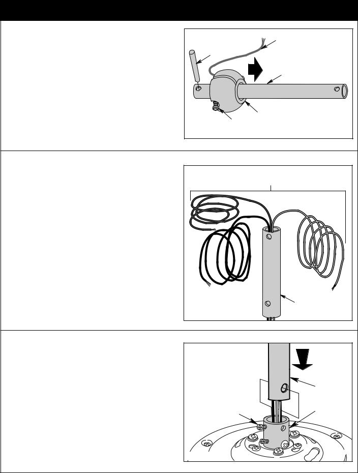
Separate, untwist and unkink the three 80” motor leads. Route the three 80” black, blue, and white motor leads through the downrod (Figure 6).
THREE 80" MOTOR LEADS (UNTWISTED)
DOWNROD
Figure 6
3.7
Loosen the two Phillips head set screws in the motor coupler for installation of the downrod (Figure 7).
Seat the downrod in the motor coupler (Figure 7).
Rotate and align the downrod holes with all the holes in the motor coupler (Figure 7).
DOWNROD
LOOSEN PHILLIPS |
MOTOR |
|
HEAD SET |
||
COUPLING |
||
SCREWS (2) |
||
|
Figure 7
emersonfans.com 7 Please contact 1-800-654-3545 for further assistance U.L. Model No.: CF205
|
|
(Continued) |
|
3.8 |
|
|
|
Align the clevis pin holes in the downrod with the holes in |
|
|
|
the motor coupler. |
|
CLIP |
|
Install the clevis pin and secure with the hairpin clip |
|
||
|
|
HAIRPIN |
|
(Figure 8). |
|
CLEVIS |
MOTOR |
The clevis pin must go through the holes in the motor |
PIN |
COUPLING |
|
|
|
||
coupler. It is critical that the clevis pin in the motor coupler |
CLEVIS |
HAIRPIN |
|
is properly installed and securely tightened. |
PIN |
CLIP |
|
|
|
|
|
Retighten the two Phillips head set screws to secure the |
|
|
|
downrod to the motor (Figure 8). |
RETIGHTEN |
|
|
! |
WARNING |
SET SCREW (2) |
|
|
|
PHILLIPS HEAD |
|
It is critical that the clevis pin and setscrews in the motor |
|
|
|
coupler are properly installed and securely tightened. |
|
|
|
Failure to verify that the pin and setscrews are properly |
|
|
|
installed could result in the fan falling. |
Figure 8 |
|
|
|
|
|
|
3.9 |
|
|
|
Make sure the grommet is properly installed in the coupler |
|
GROMMET |
|
cover, then slide the coupler cover on the downrod until it |
|
||
|
|
|
|
rests on the motor housing (Figure 9). |
|
|
|
|
|
MOTOR |
COUPLER |
|
|
HOUSING |
|
|
|
|
COVER |
Figure 9
3.10 |
ASSEMBLY |
GROMMET |
NOTE: If you installed the 6” downrod, the three |
||
|
ROD SUPPORT |
|
decorative rod assemblies and the rod support |
|
|
assembly will not be installed. Disregard Steps 3.11 |
|
|
through 3.12; proceed to Step 3.13. |
|
(Toward Top) |
Make sure the grommet is properly installed in the rod |
|
|
|
|
SCREWS (3) |
support assembly. Slide the rod support assembly onto the |
|
COVER |
downrod (Figure 10). |
|
|
|
|
COUPLER |
Then position the three screws in the rod support |
|
|
assembly toward the top (Figure 10). |
|
|
|
Figure 10 |
|
|
8 |
U.L. Model No.: CF205 |
|
(Continued) |
3.11 |
DECORATIVE |
Using the decorative rod screws (supplied), attach the |
ROD ASSEMBLY |
|
|
three decorative rod assemblies to the motor housing |
|
(Figure 11). The decorative rods must be oriented so that |
|
they lean in towards the downrod. Do not tighten the rod |
|
screws at this time. |
|
|
DECORATIVE |
|
ROD SCREW |
|
Figure 11 |
|
3.12 |
|
|
Slide the rod support assembly up the downrod until the |
DOWNROD |
|
threaded holes in the rod support align with the holes in the |
|
|
|
|
|
decorative rod assemblies (Figure 12). Secure the |
DECORATIVE |
ROD |
decorative rods to the rod support using three decorative |
ROD SCREW |
|
rod screws; do not tighten the rod screws at this time. |
|
ASSEMBLY |
|
|
SUPPORT |
Rotate the rod support assembly until the decorative rod |
|
|
assemblies are aligned vertically with the downrod |
DECORATIVE |
|
(Figure 12). Hold the rod support in this position while |
ROD ASSEMBLY |
|
tightening all six decorative rod screws securely. |
|
|
Figure 12
emersonfans.com 9 Please contact 1-800-654-3545 for further assistance U.L. Model No.: CF205
 Loading...