


 Loading...
Reference Manual
00809-0100-4811, Rev CA
February 2006
Rosemount 3300 Series
Guided Wave Radar Level and Interface Transmitters
www.rosemount.com
Reference Manual
00809-0100-4811, Rev CA
February 2006
Rosemount 3300 Series
Rosemount 3300 Series
Guided Wave Radar Level and
Interface Transmitters
NOTICE
Read this manual before working with the product. For personal and system safety, and for optimum product performance, make sure you thoroughly understand the contents before installing, using, or maintaining this product.
Within the United States, Rosemount Inc. has two toll-free assistance numbers.
Customer Central: 1-800-999-9307(7:00 a.m. to 7:00 p.m. CST)
Technical support, quoting, and order-related questions.
North American Response Center:
Equipment service needs.
1-800-654-7768 (24 hours a day – Includes Canada)
For equipment service or support needs outside the United States, contact your local Rosemount representative.
The products described in this document are NOT designed for nuclear-qualified applications.
Using non-nuclear qualified products in applications that require nuclear-qualified hardware or products may cause inaccurate readings.
For information on Rosemount nuclear-qualified products, contact your local Rosemount Sales Representative.
This product is designed to meet FCC and R&TTE requirements for a non-intentional radiator. It does not require any licensing whatsoever and has no tank restrictions associated with telecommunications issues.
This device complies with part 15 of the FCC rules. Operation is subject to the following two conditions: (1) This device may not cause harmful interference, and (2) this device must accept any interference received, including interference that may cause undesired operation.
Rosemount and the Rosemount logotype are registered trademarks of Rosemount Inc.
HART is a registered trademark of the HART Communication Foundation.
Teflon, VITON, and Kalrez are registered trademarks of DuPont Performance Elastomers.
Asset Management Solutions is a trademark of Emerson Process Management.
Cover Photo: CoverPhoto_08/CoverPhoto_07
www.rosemount.com

Reference Manual
00809-0100-4811, Rev CA
February 2006
Rosemount 3300 Series
Table of Contents
SECTION 1
Introduction
SECTION 2
Transmitter Overview
SECTION 3
Installation
Safety Messages . . . . . . . . . . . . . . . . . . . . . . . . . . . . . . . . . . . . . . . . . 1-1
Manual Overview . . . . . . . . . . . . . . . . . . . . . . . . . . . . . . . . . . . . . . . . . 1-2
Service Support . . . . . . . . . . . . . . . . . . . . . . . . . . . . . . . . . . . . . . . . . . 1-3
Theory of Operation. . . . . . . . . . . . . . . . . . . . . . . . . . . . . . . . . . . . . . . 2-1
Applications . . . . . . . . . . . . . . . . . . . . . . . . . . . . . . . . . . . . . . . . . . . . . 2-2
Components of the Transmitter . . . . . . . . . . . . . . . . . . . . . . . . . . . . . . 2-4
System Architecture. . . . . . . . . . . . . . . . . . . . . . . . . . . . . . . . . . . . . . . 2-5
Probe Selection Guide. . . . . . . . . . . . . . . . . . . . . . . . . . . . . . . . . . . . . 2-6
Dead Zones . . . . . . . . . . . . . . . . . . . . . . . . . . . . . . . . . . . . . . . . . . 2-7
Process Characteristics . . . . . . . . . . . . . . . . . . . . . . . . . . . . . . . . . . . . 2-8
Coating . . . . . . . . . . . . . . . . . . . . . . . . . . . . . . . . . . . . . . . . . . . . . . 2-8
Bridging . . . . . . . . . . . . . . . . . . . . . . . . . . . . . . . . . . . . . . . . . . . . . 2-8
Foam . . . . . . . . . . . . . . . . . . . . . . . . . . . . . . . . . . . . . . . . . . . . . . . 2-8
Vapor . . . . . . . . . . . . . . . . . . . . . . . . . . . . . . . . . . . . . . . . . . . . . . . 2-8
Measuring Range . . . . . . . . . . . . . . . . . . . . . . . . . . . . . . . . . . . . . . 2-9
Interface . . . . . . . . . . . . . . . . . . . . . . . . . . . . . . . . . . . . . . . . . . . . . 2-9
Vessel Characteristics . . . . . . . . . . . . . . . . . . . . . . . . . . . . . . . . . . . . 2-11
Heating Coils, Agitators . . . . . . . . . . . . . . . . . . . . . . . . . . . . . . . . 2-11
Tank Shape . . . . . . . . . . . . . . . . . . . . . . . . . . . . . . . . . . . . . . . . . 2-11
Safety messages . . . . . . . . . . . . . . . . . . . . . . . . . . . . . . . . . . . . . . . . . 3-1 Installation Procedure . . . . . . . . . . . . . . . . . . . . . . . . . . . . . . . . . . . . . 3-3 Before You Install . . . . . . . . . . . . . . . . . . . . . . . . . . . . . . . . . . . . . . . . 3-4 Alarm and Write Protection Switches . . . . . . . . . . . . . . . . . . . . . . . 3-4 Mounting Considerations . . . . . . . . . . . . . . . . . . . . . . . . . . . . . . . . . . . 3-6 Process Connection . . . . . . . . . . . . . . . . . . . . . . . . . . . . . . . . . . . . 3-6 Installation of Single Lead Probes in Non-metallic Tanks . . . . . . . 3-8 Mounting in Still pipes/by-pass pipes . . . . . . . . . . . . . . . . . . . . . . . 3-9 Free Space . . . . . . . . . . . . . . . . . . . . . . . . . . . . . . . . . . . . . . . . . . 3-10 Recommended Mounting Position . . . . . . . . . . . . . . . . . . . . . . . . 3-11 Insulated Tanks . . . . . . . . . . . . . . . . . . . . . . . . . . . . . . . . . . . . . . 3-12 Mechanical Installation . . . . . . . . . . . . . . . . . . . . . . . . . . . . . . . . . . . 3-13 Shortening the Probe . . . . . . . . . . . . . . . . . . . . . . . . . . . . . . . . . . 3-15 Anchoring . . . . . . . . . . . . . . . . . . . . . . . . . . . . . . . . . . . . . . . . . . . 3-18 Mounting a Centering Disc for Pipe Installations . . . . . . . . . . . . . 3-20 Electrical Installation . . . . . . . . . . . . . . . . . . . . . . . . . . . . . . . . . . . . . 3-21 Cable/conduit entries . . . . . . . . . . . . . . . . . . . . . . . . . . . . . . . . . . 3-21 Grounding. . . . . . . . . . . . . . . . . . . . . . . . . . . . . . . . . . . . . . . . . . . 3-21 Cable Selection . . . . . . . . . . . . . . . . . . . . . . . . . . . . . . . . . . . . . . 3-21 Hazardous Areas . . . . . . . . . . . . . . . . . . . . . . . . . . . . . . . . . . . . . 3-21 Power Requirements . . . . . . . . . . . . . . . . . . . . . . . . . . . . . . . . . . 3-22 Maximum Loop Resistance . . . . . . . . . . . . . . . . . . . . . . . . . . . . . 3-22 Connecting the Transmitter . . . . . . . . . . . . . . . . . . . . . . . . . . . . . 3-23
www.rosemount.com

Rosemount 3300 Series
Reference Manual
00809-0100-4811, Rev CA
February 2006
SECTION 4
Start-Up
SECTION 5
Operating the Display
Panel
Non-Intrinsically Safe Output . . . . . . . . . . . . . . . . . . . . . . . . . . . . 3-24 Intrinsically Safe Output . . . . . . . . . . . . . . . . . . . . . . . . . . . . . . . . 3-25 Optional Devices . . . . . . . . . . . . . . . . . . . . . . . . . . . . . . . . . . . . . . . . 3-26 Tri-Loop . . . . . . . . . . . . . . . . . . . . . . . . . . . . . . . . . . . . . . . . . . . . 3-26 Using More than one transmitter on the bus . . . . . . . . . . . . . . . . 3-27 751 Field Signal Indicator . . . . . . . . . . . . . . . . . . . . . . . . . . . . . . . 3-28
Safety messages . . . . . . . . . . . . . . . . . . . . . . . . . . . . . . . . . . . . . . . . . 4-1 Configuration Parameters . . . . . . . . . . . . . . . . . . . . . . . . . . . . . . . . . . 4-2 Basic Configuration . . . . . . . . . . . . . . . . . . . . . . . . . . . . . . . . . . . . 4-2 Volume Configuration . . . . . . . . . . . . . . . . . . . . . . . . . . . . . . . . . . . 4-5 Configuration using a 375 Field Communicator. . . . . . . . . . . . . . . . . . 4-7 Basic Configuration . . . . . . . . . . . . . . . . . . . . . . . . . . . . . . . . . . . . . . . 4-9 Transmitter Variables . . . . . . . . . . . . . . . . . . . . . . . . . . . . . . . . . . . 4-9 Measurement Units . . . . . . . . . . . . . . . . . . . . . . . . . . . . . . . . . . . . 4-9 Reference Gauge Height . . . . . . . . . . . . . . . . . . . . . . . . . . . . . . . . 4-9 Probe Length . . . . . . . . . . . . . . . . . . . . . . . . . . . . . . . . . . . . . . . . . 4-9 Probe Type . . . . . . . . . . . . . . . . . . . . . . . . . . . . . . . . . . . . . . . . . . 4-10 Product Dielectric . . . . . . . . . . . . . . . . . . . . . . . . . . . . . . . . . . . . . 4-10 Vapor Dielectric . . . . . . . . . . . . . . . . . . . . . . . . . . . . . . . . . . . . . . 4-10 Measurement Mode . . . . . . . . . . . . . . . . . . . . . . . . . . . . . . . . . . . 4-11 Probe Angle . . . . . . . . . . . . . . . . . . . . . . . . . . . . . . . . . . . . . . . . . 4-11 Maximum Upper Product Thickness. . . . . . . . . . . . . . . . . . . . . . . 4-11 Damping . . . . . . . . . . . . . . . . . . . . . . . . . . . . . . . . . . . . . . . . . . . . 4-11 Display Panel . . . . . . . . . . . . . . . . . . . . . . . . . . . . . . . . . . . . . . . . 4-11 4 and 20 mA Points . . . . . . . . . . . . . . . . . . . . . . . . . . . . . . . . . . . 4-12
Volume Configuration . . . . . . . . . . . . . . . . . . . . . . . . . . . . . . . . . . . . 4-13 Transmitter Variables . . . . . . . . . . . . . . . . . . . . . . . . . . . . . . . . . . 4-13 Volume Units . . . . . . . . . . . . . . . . . . . . . . . . . . . . . . . . . . . . . . . . 4-13 Tank Type. . . . . . . . . . . . . . . . . . . . . . . . . . . . . . . . . . . . . . . . . . . 4-13 Tank Dimensions . . . . . . . . . . . . . . . . . . . . . . . . . . . . . . . . . . . . . 4-13 Strapping Table . . . . . . . . . . . . . . . . . . . . . . . . . . . . . . . . . . . . . . 4-13
Configuration using The Radar Configuration Tool . . . . . . . . . . . . . . 4-14 Installing the RCT software . . . . . . . . . . . . . . . . . . . . . . . . . . . . . 4-14 Specifying the COM Port . . . . . . . . . . . . . . . . . . . . . . . . . . . . . . . 4-14 Help In RCT . . . . . . . . . . . . . . . . . . . . . . . . . . . . . . . . . . . . . . . . . 4-15 Using the Setup Wizard . . . . . . . . . . . . . . . . . . . . . . . . . . . . . . . . 4-16 Using the Setup Function . . . . . . . . . . . . . . . . . . . . . . . . . . . . . . . 4-17 Setup - Info . . . . . . . . . . . . . . . . . . . . . . . . . . . . . . . . . . . . . . . . . . 4-18 Setup - Basics . . . . . . . . . . . . . . . . . . . . . . . . . . . . . . . . . . . . . . . 4-18 Setup - Output . . . . . . . . . . . . . . . . . . . . . . . . . . . . . . . . . . . . . . . 4-19 Setup - Tank Config . . . . . . . . . . . . . . . . . . . . . . . . . . . . . . . . . . . 4-20 Setup - Volume. . . . . . . . . . . . . . . . . . . . . . . . . . . . . . . . . . . . . . . 4-22 Setup - LCD . . . . . . . . . . . . . . . . . . . . . . . . . . . . . . . . . . . . . . . . . 4-23
Special Functions . . . . . . . . . . . . . . . . . . . . . . . . . . . . . . . . . . . . . . . 4-24 TriLoop . . . . . . . . . . . . . . . . . . . . . . . . . . . . . . . . . . . . . . . . . . . . . 4-24
Display Functionality . . . . . . . . . . . . . . . . . . . . . . . . . . . . . . . . . . . . . . 5-1
Error Messages . . . . . . . . . . . . . . . . . . . . . . . . . . . . . . . . . . . . . . . . . . 5-2
Alarm and Write Protection . . . . . . . . . . . . . . . . . . . . . . . . . . . . . . . . . 5-2
TOC-2

Reference Manual
00809-0100-4811, Rev CA
February 2006
Rosemount 3300 Series
SECTION 6
Service and
Troubleshooting
Safety messages . . . . . . . . . . . . . . . . . . . . . . . . . . . . . . . . . . . . . . . . . 6-1 Advanced Configuration . . . . . . . . . . . . . . . . . . . . . . . . . . . . . . . . . . . 6-2 User defined Upper Reference Point . . . . . . . . . . . . . . . . . . . . . . . 6-2 Plotting the Measurement Signal . . . . . . . . . . . . . . . . . . . . . . . . . . 6-3 Interface Measurements for Semi-Transparent Bottom Products . 6-5 High Level Rates . . . . . . . . . . . . . . . . . . . . . . . . . . . . . . . . . . . . . . 6-7 Interface Measurements with Fully Immersed Probes . . . . . . . . . . 6-8 Service. . . . . . . . . . . . . . . . . . . . . . . . . . . . . . . . . . . . . . . . . . . . . . . . . 6-9 Analog Output Calibration . . . . . . . . . . . . . . . . . . . . . . . . . . . . . . . 6-9 Level and Distance Calibration. . . . . . . . . . . . . . . . . . . . . . . . . . . 6-10 Disturbances at the Top of the Tank . . . . . . . . . . . . . . . . . . . . . . 6-11 Amplitude Threshold Settings. . . . . . . . . . . . . . . . . . . . . . . . . . . . 6-13 Logging Measurement Data . . . . . . . . . . . . . . . . . . . . . . . . . . . . . 6-16 Saving the Transmitter Configuration . . . . . . . . . . . . . . . . . . . . . . 6-17 Removing the Transmitter Head. . . . . . . . . . . . . . . . . . . . . . . . . . 6-19 Changing the Probe . . . . . . . . . . . . . . . . . . . . . . . . . . . . . . . . . . . 6-20 Diagnostic Messages. . . . . . . . . . . . . . . . . . . . . . . . . . . . . . . . . . . . . 6-21 Troubleshooting . . . . . . . . . . . . . . . . . . . . . . . . . . . . . . . . . . . . . . 6-21 Errors . . . . . . . . . . . . . . . . . . . . . . . . . . . . . . . . . . . . . . . . . . . . . . 6-22 Warnings . . . . . . . . . . . . . . . . . . . . . . . . . . . . . . . . . . . . . . . . . . . 6-23
APPENDIX A
Reference Data
APPENDIX B
Product Certifications
Specifications. . . . . . . . . . . . . . . . . . . . . . . . . . . . . . . . . . . . . . . . . . . . A-1 Process Temperature and Pressure Rating . . . . . . . . . . . . . . . . . . A-4 Ambient Temperature. . . . . . . . . . . . . . . . . . . . . . . . . . . . . . . . . . . A-6 Dimensional drawings . . . . . . . . . . . . . . . . . . . . . . . . . . . . . . . . . . . . . A-7 Ordering Information . . . . . . . . . . . . . . . . . . . . . . . . . . . . . . . . . . . . . A-12 Spare Parts . . . . . . . . . . . . . . . . . . . . . . . . . . . . . . . . . . . . . . . . . . . . A-18
Safety Messages . . . . . . . . . . . . . . . . . . . . . . . . . . . . . . . . . . . . . . . . . B-1
EU Conformity . . . . . . . . . . . . . . . . . . . . . . . . . . . . . . . . . . . . . . . . . . . B-2
European ATEX Directive Information. . . . . . . . . . . . . . . . . . . . . . . . . B-3
Intrinsic Safety . . . . . . . . . . . . . . . . . . . . . . . . . . . . . . . . . . . . . . . . B-3
Flameproof . . . . . . . . . . . . . . . . . . . . . . . . . . . . . . . . . . . . . . . . . . . B-4
Hazardous Locations Certifications . . . . . . . . . . . . . . . . . . . . . . . . . . . B-5
Factory Mutual (FM) Approvals . . . . . . . . . . . . . . . . . . . . . . . . . . . B-5
Canadian Standards Association (CSA) Approval . . . . . . . . . . . . . B-6
IECEx Approval . . . . . . . . . . . . . . . . . . . . . . . . . . . . . . . . . . . . . . . B-7
Combination of Approvals . . . . . . . . . . . . . . . . . . . . . . . . . . . . . . . . . . B-8
Approval Drawings. . . . . . . . . . . . . . . . . . . . . . . . . . . . . . . . . . . . . . . B-11
TOC-3

Rosemount 3300 Series
Reference Manual
00809-0100-4811, Rev CA
February 2006
TOC-4
Reference Manual
00809-0100-4811, Rev CA
February 2006
Rosemount 3300 Series
Section 1 |
Introduction |
|
|
|
|
|
Safety Messages . . . . . . . . . . . . . . . . . . . . . . . . . . . . . . . . . |
page 1-1 |
|
Manual Overview . . . . . . . . . . . . . . . . . . . . . . . . . . . . . . . . |
page 1-2 |
|
Service Support . . . . . . . . . . . . . . . . . . . . . . . . . . . . . . . . . |
page 1-3 |
SAFETY MESSAGES
Procedures and instructions in this manual may require special precautions to ensure the safety of the personnel performing the operations. Information that raises potential safety issues is indicated by a warning symbol ( ). Refer to the safety messages listed at the beginning of each section before performing an operation preceded by this symbol.
Failure to follow these installation guidelines could result in death or serious injury.
•Make sure only qualified personnel perform the installation.
•Use the equipment only as specified in this manual. Failure to do so may impair the protection provided by the equipment.
Explosions could result in death or serious injury.
•Verify that the operating environment of the transmitter is consistent with the appropriate hazardous locations certifications.
•Before connecting a HART®-based communicator in an explosive atmosphere, make sure the instruments in the loop are installed in accordance with intrinsically safe or non-incendive field wiring practices.
Electrical shock could cause death or serious injury.
•Use extreme caution when making contact with the leads and terminals.
Any substitution of non-recognized parts may jeopardize safety. Repair, e.g. substitution of components etc., may also jeopardize safety and is under no circumstances allowed.
www.rosemount.com

Rosemount 3300 Series
Reference Manual
00809-0100-4811, Rev CA
February 2006
MANUAL OVERVIEW
This manual provides installation, configuration and maintenance information for the Rosemount 3300 Series Radar Transmitter.
Section 2: Transmitter Overview
•Theory of Operation
•Description of the transmitter
•Process and vessel characteristics
Section 3: Installation
•Mounting considerations
•Mechanical installation
•Electrical installation
Section 4: Start-Up
•Configuration instructions
•Configuration using the HART Communicator
•Configuration using the RCT software
Section 5: Operating the Display Panel
•Display functionality
•Error messages
Section 6: Service and Troubleshooting
•Advanced Configuration
•Error and Warning Codes
•Communication Errors
Appendix A: Reference Data
•Specifications
•Ordering Information
Appendix B: Product Certifications
•Examples of labels
•European ATEX Directive information
•FM approvals
•CSA approvals
•Drawings
1-2
Reference Manual
00809-0100-4811, Rev CA
February 2006
Rosemount 3300 Series
SERVICE SUPPORT
To expedite the return process outside of the United States, contact the nearest Rosemount representative.
Within the United States, call the Rosemount National Response Center using the 1-800-654-RSMT (7768) toll-free number. This center, available 24 hours a day, will assist you with any needed information or materials.
The center will ask for product model and serial numbers, and will provide a Return Material Authorization (RMA) number. The center will also ask for the process material to which the product was last exposed.
Rosemount National Response Center representatives will explain the additional information and procedures necessary to return goods exposed to hazardous substance can avoid injury if they are informed of and understand the hazard. If the product being returned was exposed to a hazardous substance as defined by OSHA, a copy of the required Material Safety Data Sheet (MSDS) for each hazardous substance identified must be included with the returned goods.
1-3

Rosemount 3300 Series
Reference Manual
00809-0100-4811, Rev CA
February 2006
1-4
Reference Manual
00809-0100-4811, Rev CA
February 2006
Rosemount 3300 Series
Section 2 Transmitter Overview
Theory of Operation . . . . . . . . . . . . . . . . . . . . . . . . . . . . . . page 2-1
Applications . . . . . . . . . . . . . . . . . . . . . . . . . . . . . . . . . . . . page 2-2
Components of the Transmitter . . . . . . . . . . . . . . . . . . . . page 2-4
System Architecture . . . . . . . . . . . . . . . . . . . . . . . . . . . . . . page 2-5
Probe Selection Guide . . . . . . . . . . . . . . . . . . . . . . . . . . . . page 2-6
Process Characteristics . . . . . . . . . . . . . . . . . . . . . . . . . . . page 2-8
Vessel Characteristics . . . . . . . . . . . . . . . . . . . . . . . . . . . . page 2-11
THEORY OF OPERATION The Rosemount 3300 Series Radar Transmitter is a smart, two-wire continuous level transmitter that is based on Time Domain Reflectometry (TDR) principles. Low power nano-second-pulses are guided along a probe immersed in the process media. When a pulse reaches the surface of the material it is measuring, part of the energy is reflected back to the transmitter, and the time difference between the generated and reflected pulse is converted into a distance from which the total level or interface level is calculated (see below).
The reflectivity of the product is a key parameter for measurement performance. A high dielectric constant of the media gives better reflection and a longer measuring range. A calm surface gives better reflection than a turbulent surface.
Figure 2-1. Measurement
Principle.
Signal Amplitude
Reference Pulse 
Level
Interface Level
Time
TDR_PRINCIPLES
www.rosemount.com
Rosemount 3300 Series
Reference Manual
00809-0100-4811, Rev CA
February 2006
APPLICATIONS |
The Rosemount 3300 Series Radar Transmitter program is suited for |
|
aggregate (total) level measurements on most liquids, semi-liquids, and |
|
liquid/liquid interfaces. |
|
Guided microwave technology offers highest reliability and precision which |
|
ensure measurements are virtually unaffected by temperature, pressure, |
|
vapor gas mixtures, density, turbulence, bubbling/boiling, low level, varying |
|
dielectric media, pH, and viscosity. |
|
Guided wave radar technology in combination with advanced signal |
|
processing make the 3300 transmitters suitable for a wide range of |
|
applications: |
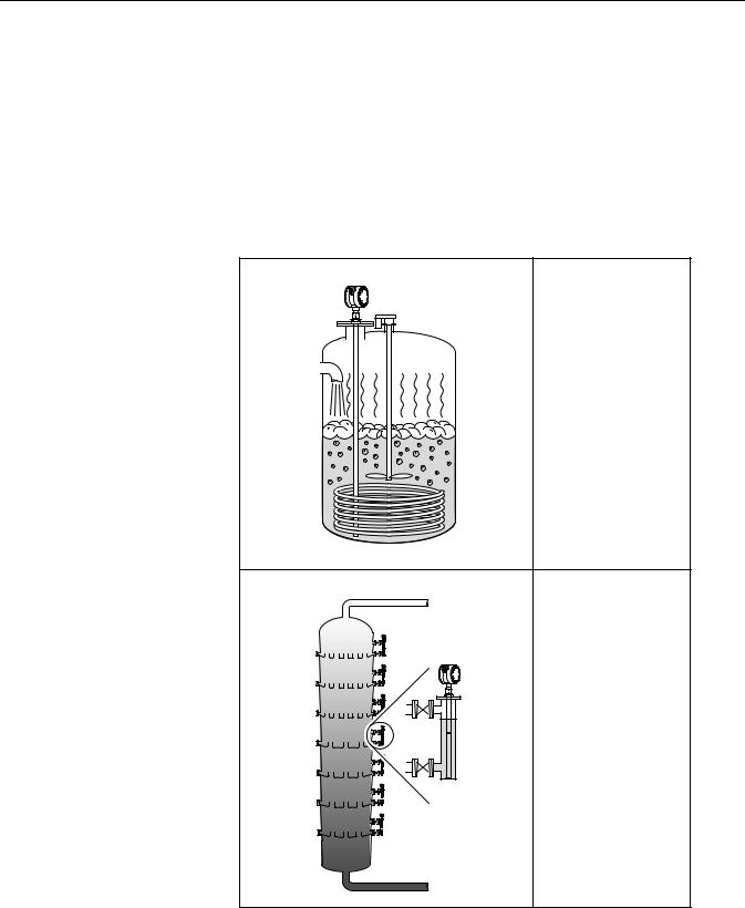
Figure 2-2. Application |
|
examples |
Boiling conditions with |
|
|
|
vapor and turbulence. For |
|
these applications the |
|
Coaxial probe is particularly |
|
suitable. |
APPLIC TURBULENCE
The Rosemount 3300 Series of transmitters is well suited for bridle applications such as distillation columns.
APPLIC BRIDLE
2-2

Reference Manual
00809-0100-4811, Rev CA
February 2006
Rosemount 3300 Series
|
Separator tank. The |
|
|
Rosemount 3302 measures |
|
|
both level and interface |
|
|
level. |
|
APPLIC SEPARATOR |
|
|
|
The Rosemount 3300 |
|
|
series is a good choice for |
|
|
underground tanks since it |
|
|
is installed on the tank top |
|
|
with the radar pulse |
|
|
concentrated near the |
|
|
probe. It can be equipped |
|
|
with probes that are |
|
SEPARATORAPPLIC |
unaffected by high and |
|
narrow openings or nearby |
||
|
||
|
objects. |
|
|
Guided wave radar |
|
|
technology is a good choice |
|
|
for reliable measurements |
|
|
in small ammonia, NGL and |
|
|
LPG tanks. |
|
APPLIC AMMONIA |
|
2-3
Rosemount 3300 Series
Reference Manual
00809-0100-4811, Rev CA
February 2006
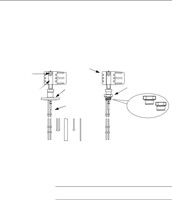
COMPONENTS OF THE TRANSMITTER
The Rosemount 3300 Series Radar Transmitter has an aluminum transmitter housing which contains advanced electronics for signal processing.
The radar electronics produces an electromagnetic pulse which is guided by the probe.
There are different probe types available for various applications: Rigid Twin Lead, Flexible Twin Lead, Rigid Single Lead, Flexible Single Lead, and Coaxial.
Figure 2-3. Transmitter components.
|
Dual Compartment Housing |
Cable Entry: |
|
½" NPT. |
|
Optional adapters: |
Threaded Process |
M20, PG13.5 |
|
|
Connections |
Radar Electronics |
Flanged Process |
Connections |
BSP (G) 
Probe
NPT 
|
|
|
|
|
|
|
|
|
R |
|
|
|
|
|
|
|
|
|
|
|
|
|
|
|
|
|
|
||
|
|
|
|
|
|
|
|
|
|
|
|
|
||
|
|
|
|
|
|
|
|
|
|
|
|
|
||
|
|
|
|
|
|
|
|
|
|
|
|
|
||
|
|
|
|
|
|
|
|
|
|
|
|
|
||
|
|
|
|
|
|
|
|
|
|
|
|
|
||
Rigid |
|
|
Co |
Fl |
|
|
|
|
||||||
Flexible |
a |
|
xi |
|
id |
|
|
|
||||||
|
|
l |
|
le |
ig |
|
|
|
|
|||||
|
|
|
|
|
xi |
|
e |
|
|
|
|
|
||
|
|
|
|
|
|
|
b |
|
|
|
|
|
|
|
|
Tw |
|
a |
|
|
|
|
Sin |
|
|
||||
|
|
i |
Twin |
|
|
|
Sin |
l |
|
|||||
|
|
L |
|
|
|
|
|
|
||||||
|
|
|
|
|
|
g |
|
e |
|
|||||
|
|
n |
|
|
|
|
|
|
|
|
g |
|
||
|
|
e |
|
|
|
|
|
|
le |
|
L |
|
||
|
|
|
a |
|
Lead |
|
e |
|
||||||
|
|
|
|
|
|
|
|
d |
|
|||||
|
|
|
d |
|
|
|
|
|
|
L |
e |
|
||
|
|
|
|
|
|
|
|
|
a |
|
||||
|
|
|
|
|
|
|
wi |
|
|
|
ad |
|
||
|
|
|
|
|
|
|
|
|
|
|
wi |
|
||
|
|
|
|
|
|
|
|
t |
|
|
|
|
|
|
|
|
|
|
|
|
|
|
h |
|
|
|
|
t |
|
|
|
|
|
|
|
|
|
weight |
|
|
h |
|
||
|
|
|
|
|
|
|
|
|
|
g |
|
|||
|
|
|
|
|
|
|
|
|
|
|
|
|
wei |
|
|
|
|
|
|
|
|
|
|
|
|
|
|
ht |
|
COMPONENTS TRANSMITTER
NOTE
Flexible and Rigid probes require different radar electronics and can not be used with the same transmitter head.
2-4
Reference Manual
00809-0100-4811, Rev CA
February 2006
Rosemount 3300 Series
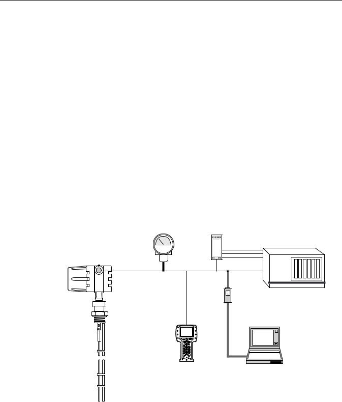
SYSTEM |
The Rosemount 3300 Series Radar Transmitter is loop-powered which |
ARCHITECTURE |
means it uses the same two wires for both power supply and output signal. |
|
The output is a 4-20 mA analog signal superimposed with a digital HART |
|
signal. |
|
By using the optional HART Tri-loop, it is possible to convert the HART signal |
|
to up to three additional 4-20 mA analog signals. |
|
With the HART protocol it is possible to use multidrop configuration. In this |
|
case communication is restricted to digital since current is fixed to the 4 mA |
|
minimum value. |
|
The transmitter can be connected to display Rosemount 751 Field Signal |
|
Indicator or it can be equipped with an integral display. |
|
The transmitter can easily be configured by using a Field Communicator or a |
|
PC with the Radar Configuration Tool software. Rosemount 3300 Series |
|
transmitters are also compatible with the AMS Suite software which also can |
|
be used for configuration. |
|
For HART communication a minimum load resistance of 250 Ohm within the |
|
loop is required. |
Figure 2-4. System architecture.
Rosemount 751 |
|
Field Signal Indicator |
Tri-Loop |
|
3300 SERIES |
3 x 4-20 mA |
DCS |
RADAR |
|
|
TRANSMITTER |
|
|
Integral
Display
4-20 mA/HART
Field
Communicator
Note! For HART communication a minimum load resistance of
250 Ohm within the loop is required.
HART modem
Radar Configuration Tool or
AMS Suite
SYSTEM_CA
2-5

Rosemount 3300 Series
Reference Manual
00809-0100-4811, Rev CA
February 2006
PROBE SELECTION GUIDE
Use the following guidelines to choose appropriate probe for your 3300 transmitter:
Table 2-1. Probe selection guide. G=Good, NR=Not Recommended, AD=Application Dependent (consult factory)
|
Coaxial |
Rigid Twin Lead |
Flexible Twin Lead |
Rigid Single Lead |
Flexible Single Lead |
|
|
|
Measurements |
|
|
||
Level |
G |
G |
G |
G |
G |
|
Interface (liquid/liquid) |
G(1) |
G |
G |
NR |
NR |
|
|
|
Process Medium |
Characteristics |
|
|
|
Changing density |
G |
G |
G |
G |
G |
|
Changing dielectric(2) |
G |
G |
G |
G |
G |
|
Wide pH variations |
G |
G |
G |
G |
G |
|
Pressure changes |
G |
G |
G |
G |
G |
|
Temperature changes |
G |
G |
G |
G |
G |
|
Condensing vapors |
G |
G |
G |
G |
G |
|
Bubbling/boiling surfaces |
G |
G |
AD |
G |
AD |
|
Foam (mechanical |
AD |
NR |
NR |
NR |
NR |
|
avoidance) |
||||||
|
|
|
|
|
||
Foam (top of foam |
NR |
AD |
AD |
AD |
AD |
|
measurement) |
||||||
|
|
|
|
|
||
Foam (foam and liquid |
NR |
AD |
AD |
NR |
NR |
|
measurement) |
||||||
|
|
|
|
|
||
Clean liquids |
G |
G |
G |
G |
G |
|
Liquid with dielectric<2.5 |
G |
AD |
AD |
AD(3) |
NR |
|
Coating liquids |
NR |
NR |
NR |
AD |
AD |
|
Viscous liquids |
NR |
AD |
AD |
AD |
G |
|
Crystallizing liquids |
NR |
NR |
NR |
AD |
AD |
|
Solids/Powders |
NR |
NR |
NR |
AD |
AD |
|
Fibrous liquids |
NR |
NR |
NR |
G |
G |
|
|
|
Tank Environment |
Considerations |
|
|
|
Probe is close |
|
|
|
|
|
|
(<12 in./30 cm) to tank wall |
G |
AD |
AD |
NR |
NR |
|
/ disturbing objects |
|
|
|
|
|
|
High turbulence |
G |
G |
AD |
G |
AD |
|
Turbulent conditions |
NR |
NR |
AD |
NR |
AD |
|
causing breaking forces |
||||||
|
|
|
|
|
||
Long and small mounting |
|
|
|
|
|
|
nozzles |
|
|
|
|
|
|
(diameter <6 in./15 cm, |
G |
AD |
NR |
NR |
NR |
|
height>diameter + 4 in./10 |
|
|
|
|
|
|
cm) |
|
|
|
|
|
|
Probe might touch nozzle / |
G |
NR |
NR |
NR |
NR |
|
disturbing object |
||||||
|
|
|
|
|
||
Liquid or vapor spray might |
|
|
|
|
|
|
touch probe |
G |
NR |
NR |
NR |
NR |
|
|
|
|
|
|
|
|
Disturbing EMC |
AD |
NR |
NR |
NR |
NR |
|
environment in tank |
||||||
|
|
|
|
|
||
(1)Not in fully immersed applications.
(2)For overall level applications a changing dielectric has no effect on the measurement. For interface measurements a changing dielectric of the top fluid will degrade the accuracy of the interface measurement.
(3)OK when installed in pipe.
2-6
Reference Manual
00809-0100-4811, Rev CA
February 2006
Rosemount 3300 Series
Dead Zones |
The measuring range depends on probe type and properties of the product. |
|
The Upper Dead Zone is the minimum measurement distance between the |
|
upper reference point and the product surface. The Upper Dead Zone varies |
|
between 4 - 20 in. (0.1 and 0.5 m) depending on probe type and product. |
At the end of the probe the measuring range is reduced by the Lower Dead Zone. The Lower Dead Zone also varies depending on probe type and product.
Figure 2-5 illustrates how the measuring range is related to the Dead Zones:
Figure 2-5. Dead Zones
Upper Reference Point
 Upper Dead Zone
20mA
100% |
Maximum |
0 - |
Measuring Range |
Range |
|
4mA |
ZONES |
Lower Dead Zone |
|
|
DEAD |
Table 2-2. Dead Zones for different probe types
|
Dielectric |
Coaxial Probe |
Rigid Twin |
Flexible Twin |
Rigid Single |
Flexible Single |
|
Constant |
|
Lead Probe |
Lead Probe |
Lead Probe |
Lead Probe |
Upper |
2 |
4 in. (10 cm) |
4 in. (10 cm) |
8 in. (20 cm) |
4 in. (10 cm) |
20 in. (50 cm) |
Dead Zone |
80 |
4 in. (10 cm) |
4 in. (10 cm) |
5.9 in. (15 cm) |
4 in. (10 cm) |
5.9 in. (15 cm) |
Lower |
2 |
2 in. (5 cm) |
2.8 in. (7 cm) |
5.9 in. (15 cm) |
4 in. (10 cm)(1) |
4.7 in. (12 cm) |
Dead Zone |
80 |
1.2 in. (3 cm) |
2 in. (5 cm) |
2 in. (5 cm) |
2 in. (5 cm) |
2 in. (5 cm) |
(1) Dead Zone=8 inch (20 cm) when SST centering disc is mounted. The PTFE centering disc does not affect the Dead Zone.
NOTE
The measurement accuracy is reduced in the Dead Zones. It may even be impossible to make any measurements at all in those regions. Therefore the 4-20 mA set points should be configured outside the Dead Zones.
2-7

Rosemount 3300 Series
Reference Manual
00809-0100-4811, Rev CA
February 2006
PROCESS |
The Rosemount 3300 Series has a high sensitivity due to its advanced signal |
CHARACTERISTICS |
processing and high signal to noise ratio, which makes it able to handle |
|
various disturbances. However, the following circumstances should be |
|
considered before mounting the transmitter. |
Coating |
Coating on the probe should be avoided since the sensitivity of the transmitter |
|
may be decreased leading to measurement errors. In viscous or sticky |
|
applications, periodic cleaning may be required. |
|
For viscous or sticky applications, it is important to choose a suitable probe: |
Table 2-3. Probe type guide for different product viscosity
Bridging
Coaxial |
Twin Lead |
Single Lead |
|
Maximum viscosity |
|
|
|
|
500 cP |
1500 cP |
8000 cP(1)(2) |
|
Coating/Build-up |
|
|
|
|
Coating not recommended |
Thin coating allowed, but no |
Coating allowed |
|
bridging |
|
(1)Consult factory if agitation/turbulence and high viscous products.
(2)HTHP and HP single probes should be used with precaution in viscous or crystallizing media. Cooling of high temperature vapor in the upper part of the probe may lead to condensation and deposition that blocks the measurement signal.
Maximum measurement error due to coating is 1-10% depending on probe type, dielectric constant, coating thickness and coating height above product surface.
Heavy coating that results in product bridging across the two probes for twin lead versions, or between the pipe and the inner rod for coaxial probes, will cause erroneous level readings and must be prevented. Single lead probes are preferred in this case. If a Twin Lead probe is required, regular cleaning may be necessary.
Foam |
How well the Rosemount 3300 Series Radar Transmitter measures in foamy |
|
applications depends upon the properties of the foam; light and airy or dense |
|
and heavy, high or low dielectrics, etc. If the foam is conductive and creamy |
|
the transmitter will probably measure the surface of the foam. If the foam is |
|
less conductive the microwaves will probably penetrate the foam and |
|
measure the liquid surface. |
Vapor |
In some applications, as ammonia, there is heavy vapor above the product |
|
surface that will influence the level measurement. The Rosemount 3300 |
|
Series Radar Transmitter can be configured to compensate for the influence |
|
of vapor. |
2-8
Reference Manual
00809-0100-4811, Rev CA
February 2006
Rosemount 3300 Series
Measuring Range |
The measuring range differs depending on probe type and characteristics of |
|
the application. The values given in Table 2-4 can be used as a guideline for |
|
clean liquids. |
Table 2-4. Measuring Range
Coaxial |
Rigid Twin Lead |
Flexible Twin Lead |
Rigid Single Lead |
Flexible Single Lead |
|
|
Maximum Measuring Range |
|
|
19 ft 8 in. (6 m) |
9 ft 10 in. (3 m) |
77 ft 1in. (23.5 m) |
9 ft 10 in. (3 m) |
77 ft 1in. (23.5 m) |
|
Minimum Dielectric |
Constant at Maximum |
Measuring Range |
|
Standard & HP: |
1.9 |
1.6 up to 33 ft (10 m) |
2.5 |
2.5 up to 36.1 ft (11 m) |
1.4 |
|
2.0 up to 66 ft (20 m) |
(1.7 if installed in a |
5.0 up to 66 f (20 m) |
HTHP: |
|
2.4 up to 77 ft 1 in. (23.5 m) |
metallic bypass or stilling |
7.5 up to 77 ft 1 in. (23.5 m) |
2.0 up to 13 ft (4 m) |
|
|
well) |
|
2.5 up to 19 ft 8 in. (6 m) |
|
|
|
|
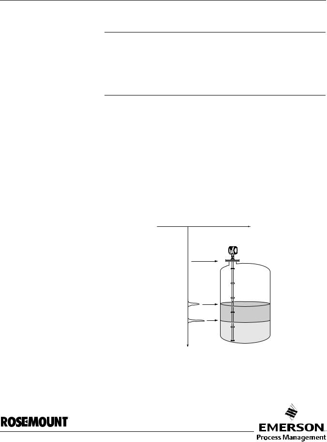
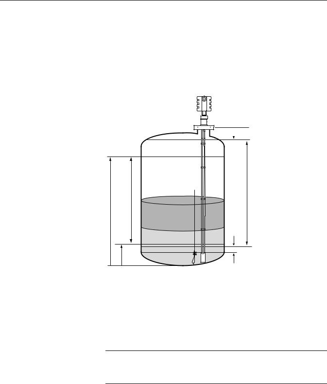
Interface
Figure 2-6. Interface measurement with a Rosemount 3302 and a Rosemount 3301 (fully immersed probe).
The maximum measuring range differs depending on application according to:
•Disturbing objects close to the probe.
•Media with higher dielectric constant (εr) gives better reflection and allows a longer measuring range.
•A calm surface gives better reflection than a turbulent surface. For a turbulent surface the measuring range might be reduced.
•Surface foam and particles in the tank atmosphere are also circumstances that might affect measuring performance.
•Coating/contamination can reduce the measuring range.
•Disturbing EMC environment in tank.
Rosemount 3302 is the ideal choice for measuring the interface of oil and water, or other liquids with significant dielectric differences. It is also possible to measure interface with a Rosemount 3301 in applications where the probe is fully immersed in the liquid.
3302 |
3301 |
|
|
|
|
|
|
|
Level |
|
|
|
|
|
|
CA |
|
|
|
|
|
|
|
|
|
|
|
|
|
||
|
|
|
|
|
|
|
|
|
|
|
||||
|
|
|
|
|
|
|
Interface Level |
|
|
|
|
|
Level=Interface Level |
INTERFACE |
|
|
|
|
|
|
|
|
|
|
|
|
|||
|
|
|
|
|
|
|
|
|
|
|
|
|
|
|
|
|
|
|
|
|
|
|
|
|
|
|
|
|
BRIDLE |
|
|
|
|
|
|
|
|
|
|
|
|
|
|
|
|
|
|
|
|
|
|
|
|
|
|
|
|
|
|
|
|
|
|
|
|
|
|
|
|
|
|
|
|
|
Coaxial, Rigid twin, Flexible twin and Rigid Single lead probes can be used for measuring interfaces. The coaxial probe is the preferred choice for clean liquids and when the bridle is not fully immersed. In applications with a fully immersed probe, the twin lead probes are recommended for nozzle installations, and the rigid single lead probe is best for bridle mounting.
2-9

Rosemount 3300 Series
Reference Manual
00809-0100-4811, Rev CA
February 2006
Figure 2-7. Reduction of maximum measuring range for Flexible Twin Lead probe
For measuring the interface level, the transmitter uses the residual wave of the first reflection. Part of the wave, which was not reflected at the upper product surface, continues until it is reflected at the lower product surface. The speed of this wave depends fully on the dielectric constant of the upper product.
If interface is to be measured, the following criteria have to be fulfilled:
•The dielectric constant of the upper product must be known. The Radar Configuration Tools software has a built-in dielectric constant calculator to assist users in determining the dielectric constant of the upper product (see “Dielectrics” on page 4-21).
•The dielectric constant of the upper product must have a lower dielectric constant than the lower product in order to have a distinct reflection.
•The difference between the dielectric constants for the two products must be larger than 10.
•Maximum dielectric constant for the upper product is 10 for the coaxial probe and 5 for twin lead probes.
•The upper product thickness must be larger than 8 inches (0.2 m) for the flexible twin lead probe and 4 inches (0.1 m) for the rigid twin lead and coaxial probes in order to distinguish the echoes of the two liquids.
The maximum allowable upper product thickness/measuring range is primarily determined by the dielectric constants of the two liquids.
Target applications include interfaces between oil/oil-like and water/water-like liquids. For such applications the upper product dielectric constant is low (<3) and the lower product dielectric constant is high (>20), and the maximum measuring range is only limited by the length of the coaxial and rigid twin lead probes.
For the flexible twin lead probe, the reduction of maximum measuring range (65 ft/20 m), can be gained from Figure 2-7 on page 2-10.
However, characteristics varies widely between different applications. For other product combinations, consult factory.
Reduction of Maximum Measuring Range for |
|
|
different Upper Product Dielectric constants. |
|
|
Flexible Twin Lead probe (ft/m) |
3.5 |
SCALE |
|
||
|
|
|
|
3 |
REDUCTIONINTERFACE |
|
2 |
|
|
|
|
Maximum Upper Product Thickness (ft/m)
2-10

Reference Manual
00809-0100-4811, Rev CA
February 2006
Rosemount 3300 Series
Emulsion Layers
Sometimes there is an emulsion layer (mix of the products) between the two products which, depending on its characteristics, will affect interface measurements.
Please consult factory for guidelines on how to handle emulsion layers.
VESSEL CHARACTERISTICS
Heating Coils, Agitators
Tank Shape
The Rosemount 3300 Series Radar Transmitter is relatively insensitive to objects in the tank since the radar signal is transmitted along a probe.
Avoid physical contact between probes and agitators as well as applications with strong fluid movement unless the probe is anchored. If the probe can move within 1 ft (30 cm) away from any object, such as an agitator, during operation then probe tie-down is recommended.
In order to stabilize the probe for side forces, it is possible to hang a weight at the probe end (flexible probes only) or fix/guide the probe to the tank bottom.
The guided wave radar transmitter is insensitive to the tank shape. Since the radar signal travels along a probe, the shape of the tank bottom has virtually no effect on the measurement performance. The transmitter handles flat or dish-bottom tanks equally well.
2-11

Rosemount 3300 Series
Reference Manual
00809-0100-4811, Rev CA
February 2006
2-12
Reference Manual
00809-0100-4811, Rev CA
February 2006
Rosemount 3300 Series
Section 3 |
Installation |
SAFETY MESSAGES
Safety messages . . . . . . . . . . . . . . . . . . . . . . . . . . . . . . . . . page 3-1 Installation Procedure . . . . . . . . . . . . . . . . . . . . . . . . . . . . page 3-3 Before You Install . . . . . . . . . . . . . . . . . . . . . . . . . . . . . . . . page 3-4 Mounting Considerations . . . . . . . . . . . . . . . . . . . . . . . . . page 3-6 Mechanical Installation . . . . . . . . . . . . . . . . . . . . . . . . . . . page 3-13 Electrical Installation . . . . . . . . . . . . . . . . . . . . . . . . . . . . . page 3-21 Optional Devices . . . . . . . . . . . . . . . . . . . . . . . . . . . . . . . . . page 3-26
Procedures and instructions in this section may require special precautions to ensure the safety of the personnel performing the operations. Information that raises potential safety issues is indicated by a warning symbol (  ). Please refer to the following safety messages before performing an operation preceded by this symbol.
Explosions could result in death or serious injury:
Verify that the operating environment of the transmitter is consistent with the appropriate hazardous locations certifications.
Before connecting a HART-based communicator in an explosive atmosphere, make sure the instruments in the loop are installed in accordance with intrinsically safe or non-incendive field wiring practices.
Do not remove the gauge cover in explosive atmospheres when the circuit is alive.
Failure to follow safe installation and servicing guidelines could result in death or serious injury:
Make sure only qualified personnel perform the installation.
Use the equipment only as specified in this manual. Failure to do so may impair the protection provided by the equipment.
Do not perform any service other than those contained in this manual unless you are qualified.
Process leaks could result in death or serious injury.
Make sure that the transmitter is handled carefully. If the Process Seal is damaged, gas might escape from the tank if the transmitter head is removed from the probe.
www.rosemount.com

Rosemount 3300 Series
Reference Manual
00809-0100-4811, Rev CA
February 2006
High voltage that may be present on leads could cause electrical shock:
Avoid contact with leads and terminals.
Make sure the main power to the 3300 transmitter is off and the lines to any other external power source are disconnected or not powered while wiring the gauge.
Probes covered with plastic and/or with plastic discs may generate an ignition-capable level of electrostatic charge under certain extreme conditions. Therefore, when the probe is used in a potentially explosive atmosphere, appropriate measures must be taken to prevent electrostatic discharge.
3-2

Reference Manual
00809-0100-4811, Rev CA
February 2006
Rosemount 3300 Series
INSTALLATION |
Follow these steps for proper installation: |
||||||||||||||||
PROCEDURE |
|
|
|
|
|
|
|
|
|
|
|
|
|
|
|
|
|
|
|
|
|
|
|
|
|
|
|
|
|
|
|
|
|||
|
|
|
Review Installation |
|
|
||||||||||||
|
|
|
|
Considerations |
|
|
|||||||||||
|
|
|
|
(see page 3-6) |
|
|
|||||||||||
|
|
|
|
|
|
|
|
|
|
|
|
|
|
|
|
|
|
|
|
|
|
|
|
|
|
|
|
|
|
|
|
|
|
|
|
|
|
|
|
|
|
|
|
|
|
|
|
|
|
|
|||
|
|
|
Check switches for |
|
|
||||||||||||
|
|
|
4-20 mA AlarmOutput |
|
|
||||||||||||
|
|
|
|
(see page 3-4) |
|
|
|||||||||||
|
|
|
|
|
|
|
|
|
|
|
|
|
|
|
|
|
|
|
|
|
|
|
|
|
|
|
|
|
|
|
|
|
|
|
|
|
|
|
|
|
|
|
|
|
|
|
|
|
|
|
|||
|
|
|
Mount the transmitter |
|
|
||||||||||||
|
|
|
|
(see page 3-13) |
|
|
|||||||||||
|
|
|
|
|
|
|
|
|
|
|
|
|
|
|
|
|
|
|
|
|
|
|
|
|
|
|
|
|
|
|
|
|
|
|
|
|
|
|
|
|
|
|
|
|
|
|
|
|
|
|
|||
|
|
|
Wire the transmitter |
|
|
||||||||||||
|
|
|
|
(see page 3-21) |
|
|
|||||||||||
|
|
|
|
|
|
|
|
|
|
|
|
|
|
|
|
|
|
|
|
|
|
|
|
|
|
|
|
|
|
|
|
|
|
|
|
|
|
|
|
|
|
|
|
|
|
|
|
|
|
|
|
|
|
|
|
|
|
Make sure covers |
|
|
|||||||||||
|
|
|
|
and cable/conduit |
|
|
|||||||||||
|
|
|
|
connections are |
|
|
|||||||||||
|
|
|
|
|
|
|
tight. |
|
|
||||||||
|
|
|
|
|
|
|
|
|
|
|
|
|
|
|
|
|
|
|
|
|
|
|
|
|
|
|
|
|
|
|
|
|
|
|
|
|
|
|
|
|
|
|
|
|
|
|
|
|
|
|
|
|
|
|
|
|
|
|
Power Up the |
|
|
||||||||||
|
|
|
|
|
transmitter |
|
|
||||||||||
|
|
|
|
|
|
|
|
|
|
|
|
|
|
|
|
|
|
|
|
|
|
|
|
|
|
|
|
|
|
|
|
|
|
|
|
|
|
|
|
|
|
|
|
|
|
|
|
|
|
|
|||
|
|
|
|
Configure the |
|
|
|||||||||||
|
|
|
|
|
transmitter |
|
|
||||||||||
|
|
|
|
(see page 4-1) |
|
|
|||||||||||
|
|
|
|
|
|
|
|
|
|
|
|
|
|
|
|
|
|
|
|
|
|
|
|
|
|
|
|
|
|
|
|
|
|
|
|
|
|
|
Verify measurements |
|
|
||||||||||||
|
|
|
|
|
|
|
|
|
|
|
|
|
|
|
|
|
|
|
|
|
|
|
|
|
|
|
|
|
|
|
|
|
|
|
|
|
|
|
|
|
|
|
|
|
|
|
|
|
|
|
|
||
|
|
|
|
|
Set the Write |
|
|
||||||||||
|
|
|
|
|
|
|
|||||||||||
|
|
|
|
Protection Switch |
|
|
|||||||||||
|
|
|
|
|
|||||||||||||
|
|
|
|
|
|
|
|
|
|
|
|
|
|
|
|
|
|
|
|
|
|
|
|
|
|
|
|
|
|
|
|
|
|
|
|
|
|
|
|
|
|
|
|
|
|
|
|
|
|
|
|
|
|
|
NOTE! |
||||||||||||||||
|
Disconnect power supply before setting the Write Protection. |
||||||||||||||||
|
|
|
|
|
|
|
|
|
|
|
|
|
|
|
|
|
|
3-3

Rosemount 3300 Series
Reference Manual
00809-0100-4811, Rev CA
February 2006
BEFORE YOU INSTALL
Alarm and Write
Protection Switches
Electronic boards are electrostatically sensitive. Failure to observe proper handling precautions for static-sensitive components can result in damage to the electronic components. Do not remove the electronic boards from the 3300 Radar Transmitter.
NOTE
To ensure long life for your radar transmitter, and to comply with hazardous location installation requirements, tighten covers on both sides of the electronics housing.
Table 3-1. 3300 Radar Transmitter Switch Settings
Switch |
Description |
Default Setting |
Position Settings |
Bank |
|||
|
|
|
|
Alarm |
4–20 mA Alarm Output |
High |
High, Low |
|
|
|
|
Write |
Security Write |
Disabled (OFF) |
ON = Enabled, |
Protect |
Protection |
|
OFF = Disabled |
Table 3-2. Analog Output: Standard Alarm Values vs. Saturation Values
Level |
4–20 mA Saturation Values |
4–20 mA Alarm Value |
|
|
|
Low |
3.9 mA |
3.75 mA |
High |
20.8 mA |
21.75 mA |
Table 3-3. Analog Output: NAMUR-Compliant Alarm Values vs. Saturation Values
Level |
4–20 mA Saturation Values |
4–20 mA Alarm Value |
|
|
|
Low |
3.8 mA |
3.6 mA |
|
|
|
High |
20.5 mA |
22.5 mA |
|
|
|
The transmitter monitors its own operation. This automatic diagnostic routine is a timed series of checks repeated continuously. If the diagnostic routine detects a failure in the transmitter, the 4–20 mA output is driven upscale (high) or downscale (low) depending on the position of the Alarm switch.
Security write protection prevents unauthorized access to configuration data through the Rosemount Configuration Tool (RCT) software, a Field Communicator or AMS Suite software.
3-4
Reference Manual
00809-0100-4811, Rev CA
February 2006
Rosemount 3300 Series
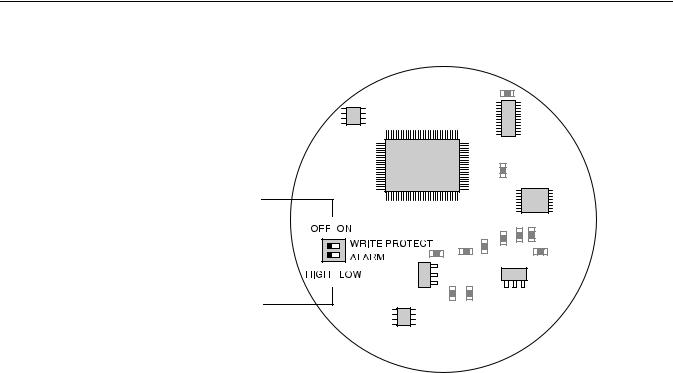
Figure 3-1. Switches for Alarm and Write Protection
Write Protection
Alarm Output
SWITCH WRP ALARM
To set the Alarm and Write Protect switches do the following:
1.Remove the cover on the circuit side (see main label).
2.To set the 4-20 mA alarm output to Low, move the Alarm switch to the LOW position. HIGH is the factory default setting (see Figure 3-1).
3.To enable the security write protection feature, move the Write Protect switch to the ON position. The OFF position is the factory default setting (see Figure 3-1).
4.Replace and tighten the cover.
3-5
Rosemount 3300 Series
Reference Manual
00809-0100-4811, Rev CA
February 2006
MOUNTING CONSIDERATIONS
Process Connection
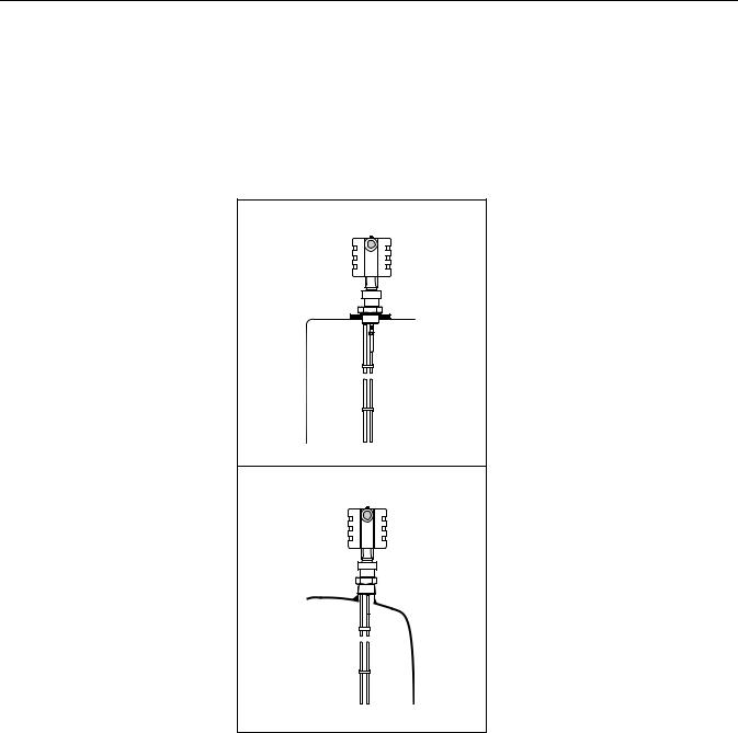
Figure 3-2. Mounting on tank roof using threaded connection
Before you install the Rosemount 3300 Series Radar Transmitter, be sure to consider specific mounting requirements, vessel characteristics and process characteristics.
The 3300 Series has a threaded connection for easy mounting on the tank roof. It can also be mounted on a nozzle by using different flanges.
Threaded Connection
Mounting on tank roof.
MOUNT THREADED ROOF
Mounting in threaded pipe.
MOUNT THREADED PIPE
3-6
Loading...