


Fisher Vee-Ball V150
www.Fisher.com
Fisherr Vee-Ballt V150 and V300
NPS 14 through 20 Rotary Control Valves
Contents
Introduction 1.................................
Scope of Manual 1.............................
Description 1.................................
Specifications 2...............................
Installation 2..................................
Maintenance 5.................................
Packing Maintenance 5.........................
Stopping Leakage 6........................
Packing Replacement 6.....................
Ball Seal Replacement 7........................
Disassembly 9.............................
Assembly 10..............................
Bearing and Ball Maintenance 11.................
Disassembly 12............................
Assembly 13..............................
Actuator Mounting 16.........................
Determining Open Position 17...............
Parts Ordering 18...............................
Parts List 18...................................
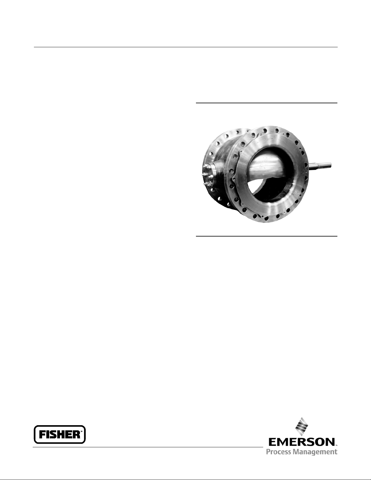
Figure 1. Fisher V150 and V300 Vee-Ball NPS 16
Valve
W6087
Introduction
Scope of Manual
This instruction manual provides installation, operation, maintenance, and parts ordering information for NPS 14, 16,
and 20 V150 and for NPS 14 and 16 V300 rotary control valves. For smaller valves (NPS 1 through 12), refer to the
Vee-Ball V150, V200 and V300 Rotary Control Valves NPS 1 through 12 instruction manual (D101554X012). For
information on ENVIRO-SEALt packing, see the ENVIRO-SEAL Packing System for Rotary Valves instruction manual
(D101643X012). Refer to separate manuals for information concerning the actuator, positioner, and mounted
accessories.
Do not install, operate, or maintain V150 and V300 valves without being fully trained and qualified in valve, actuator,
and accessory installation, operation, and maintenance. To avoid personal injury or property damage, it is important
to carefully read, understand, and follow all the contents of this manual, including all safety cautions and warnings. If
you have any questions about these instructions, contact your Emerson Process Management sales office before
proceeding.
Description
The V150 or V300 Vee-Ball valve with a V-notch ball is used in throttling or on-off service. The V150 valve (figure 1) is a
raised-face flanged construction available in CL150. The V300 valve is a raised-face flanged construction available in
CL300. The splined valve shaft connects to a variety of rotary actuators.
Instruction Manual
D101957X012
V150 and V300 Valves
November 2011
Instruction Manual
D101957X012
V150 and V300 Valves
November 2011
2
Table 1. Specifications
Valve Sizes and End Connection Styles
V150: NPS 14, 16, and 20 with CL150 raised-face
flangesasshownintable3
V300: NPS 14 and 16 with CL300 raised-face flanges
asshownintable3
Maximum Inlet Pressure
(1)
Consistent with applicable ASME B16.34 or
EN 12516-1 ratings
Standard Flow Direction
Forward (into the convex sealing face of the ball)
Actuator Mounting
J Right-hand, or J left-hand as viewed from the
upstream end of the valve. Standard valve
construction with standard ball rotation is with
right-hand mounting. Optional valve construction
with optional ball rotation for left-hand mounting is
available upon request.
Ball Rotation
Standard: Ball rotates Counterclockwise to Close
(CCW) when viewed from actuator side of valve
Optional: Ball rotates Clockwise to Close (CW)
Maximum ball rotation is 90 degrees
Valve/Actuator Action
With diaphragm or piston rotary actuator,
field-reversible between push-down-to-close
(extending actuator rod closes valve) and
push-down-to-open (extending actuator rod opens
valve)
1. The pressure/temperature limits inthismanual and any applicable standard or code limitation for valveshouldnot be exceeded.
Table2.ValveSizes,DriveShaftDiameters, and Valve Assembly Weights
VALVE SIZE DRIVE SHAFT DIAMETER VALVE ASSEMBLY WEIGHT
mm NPS mm Inch
kg lb
V150 V300 V150 V300
350 14 44.5 1-3/4 206 374 545 825
400 16
54.0 2-1/8
333 510 735 1125
54.0 x 50.8 2-1/8 x 2
500
(1)
20
(1)
63.5 2-1/2 524 --- 1155 ---
1. NPS 20 available only for V150, not for V300 valves.
Table 3. Valve Sizes, End Connection Styles, and Ratings
(1)(2)
VALVE BODY
MATERIAL
FLANGE COMPATIBILITY RATING FACE-TO-FACE DIMENSION
WCC steel (standard)
CL150 (V150) raised-face ASME B16.34 CL150
NPS 14 and 16 Valves: ASME B16.10 Short
NPS 20 Valves: 508 mm (20 inches)
CL300 (V300) raised-face ASME B16.34 CL300
NPS 14 Valves: 381 mm (15 inches)
NPS 16 Valves: 406 mm (16 inches)
CG8M (317 SST)
CL150 (V150) raised-face ASME B16.34 CL150
NPS 14 and 16 Valves: ASME B16.10 Short
NPS 20 Valves: 508 mm (20 inches)
CL300 (V300) raised-face ASME B16.34 CL300
NPS 14 Valves: 381 mm (15 inches)
NPS 16 Valves: 406 mm (16 inches)
1. Do not exceed the materialtemperature capabilities or the pressure drop limitations shown in bulletin 51.3:Vee-Ball.
2. The pressure/temperature limits inthismanual and any application code limitations, should not be exceeded.
Specifications
Specifications for these valves are shown in table 1 and bulletin 51.3:Vee-Ball.
Installation
Key numbers are shown in figure 10, unless otherwise indicated.

Instruction Manual
D101957X012
V150 and V300 Valves
November 2011
3
WARNING
Always wear protective gloves, clothing, and eyewear when performing any maintenance operations to avoid personal
injury.
Personal injury or equipment damage caused by sudden release of pressure may result if the valve assembly is installed
where service conditions could exceed either the valve body rating or the mating pipe flange joint rating. To avoid such
injury or damage, provide a relief valve for overpressure protection as required by government or accepted industry codes
and good engineering practices.
Check with your process or safety engineer for any additional measures that must be taken to protect against process
media.
CAUTION
When ordered, the valve configuration and construction materials were selected to meet particular pressure, temperature,
pressure drop and controlled fluid conditions. Responsibility for the safety of process media and compatibility of valve
materials with process media rests solely with the purchaser and end-user. Since some valve body/trim material
combinations are limited in their pressure drop and temperature ranges, do not apply any other conditions to the valve
without first contacting your Emerson Process Management sales office.
Install the valve with the drive shaft in the horizontal position as shown in figure 1.
WARNING
Do not allow the valve to be installed in t he pipeline with thedrive shaft in the vertical position because of excessive wear to
component valve parts.
1. If the valve is to be stored before installation, protect the flange mating surfaces and keep the valve cavity dry and
free of foreign material.
2. Install a three-valve bypass around the control valve assembly if continuous operation will be necessary during
inspection and maintenance of the valve.
3. Mounting the Actuator:
a. The valve is normally shipped as part of a control valve assembly, with the actuator mounted on the valve. The
factory makes actuator/valve adjustments before the valve is shipped.
b. If the valve and actuator have been purchased separately or if the actuator has been removed, mount the
actuator according to the Actuator Mounting section of this manual.
4. Be certain the valve and adjacent pipelines are free of any foreign material that could damage the valve seating
surfaces.
5. Be sure the mating line flanges are aligned. Provide standard flat sheet flange gaskets (or spiral wound gaskets with
compression-controlling centering rings) that are compatible with the process fluid.
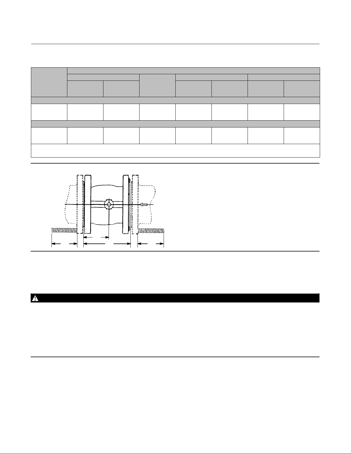
Refer to figure 2 for required clearance for valve installation and stud length. Lubricate the studs with anti-seize
lubricant.
6. Install the valve using studs and nuts to connect the valve flanges to the pipeline flanges. The seal protector ring
(key 3) end of the valve requires longer line flange studs than standard (see figure 2).
Instruction Manual
D101957X012
V150 and V300 Valves
November 2011
4
Table 4. Required Clearances for Installation of Fisher V150 and V300 Valves
VALVE
SIZE,
NPS
DIMENSION
A
B
M
(2)
(Min.) N
CL150
ASME B16.10
(Short)
(1)
CL300
CL150
ASME B16.10
(Short)
(1)
CL300 CL150 CL300
mm
14
16
20
(3)
381
406
508
381
406
---
175
178
235
(3)
152
152
178
197
210
---
133
133
159
178
190
---
Inch
14
16
20
(3)
15.00
16.00
20.00
15.00
16.00
---
6.88
7.00
9.25
(3)
6.00
6.00
7.00
7.75
8.25
---
5.25
5.25
6.25
7.00
7.50
---
1. ASME B16.10 (Short)appliesto NPS 14 and 16 valves only.
2. Inlet flange studboltlength is longer than the standard length as specified in ASME B16.5.
3. NPS 20, CL150valves do not comply with ASMEB16.10(Short). NPS 20 valves are not available in CL300.
Figure 2. Required Clearances for Installation of Fisher V150 and V300 Valves
MAN
B
13B6967-B
A6064-1
Do not attempt to use standard-length line flange studs for the seal protector end of the valve. Refer to figure 2 for
length of flange studs required.
Install all remaining studs. Tighten the nuts in a criss-cross sequence to ensure the flange gaskets are properly loaded.
WARNING
The valve drive shaft is not necessarily grounded to the pipeline when installed. Personal injury or property damage could
result if the process fluid or the atmosphere around the valve is flammable, from an explosion caused by a discharge of
static electricity from the valve components. If the valve is installed in a hazardous area, electrically bond the drive shaft to
the valve.
Standard PTFE packing is composed of a partially conductive carbon-filled PTFE female adaptor with PTFE V-ring packing.
Standard graphite packing is composed of all conductive graphite ribbon packing rings. Alternate shaft-to-valve body
bonding is available for hazardous service areas where the standard packing is not sufficient to bond the shaft to the valve
(see the following step and figure 4).
7. For hazardous applications, attach the optional bonding strap assembly (key 131, figure 4) to the valve drive shaft
(key 6) with the clamp (key 130, figure 4) and connect the other end of the bonding strap assembly to the valve
body with the cap screw (key 23).
8. Connect pressure lines to the actuator as indicated in the actuator instruction manual. When an auxiliary manual
actuator is used with a power actuator, install a bypass valve on the power actuator (if one is not supplied) for use
during manual operation.

Instruction Manual
D101957X012
V150 and V300 Valves
November 2011
5
WARNING
Personal injury could result from packing leakage. Valve packing was tightened before shipment; however, the packing
might need some readjustment to meet specific service conditions. Check with your process or safety engineer for any
additional measures that must be taken to protect against process media.
If the valve has ENVIRO-SEAL live-loaded packing installed, this initial re-adjustment will probably not be required.
Refer to the ENVIRO-SEAL Packing System for Rotary Valves instruction manual (D101643X012) for packing
instructions.
Maintenance
Valve parts are subject to normal wear and must be inspected and/or replaced as necessary. The frequency of
inspection and replacement depends upon the severity of service conditions.
WARNING
The Vee-ball closes with a cutting motion. To avoid personal injury, keep hands, tools, and other objects away from the ball
while stroking the valve.
Avoid personal injury from sudden release of process pressure. Before performing any maintenance operations:
D Do not remove the actuator from the valve while the valve is still pressurized.
D Disconnect any operating lines providing air pressure, electric power, or a control signal to the actuator. Make sure the
actuator cannot suddenly open or close the valve.
D Use bypass valves or completely shut off the process to isolate the valve from process pressure. Relieve process pressure
on both sides of the valve. Drain the process media from both sides of the valve.
D Vent the power actuator loading pressure.
D Uselock-outprocedurestobesurethattheabovemeasures stay in effect while you work on the equipment.
D Always wear protective gloves, clothing, and eyewear when performing any maintenance operations to avoid personal
injury.
D The valve packing area may contain process fluids that are pressurized, even when the valve has been removed from the
pipeline. Process fluids may spray out under pressure when removing the packing hardware or packing rings.
D Check with your process or safety engineer for any additional measures that must be taken to protect against process
media.
Packing Maintenance
Key numbers are shown in figure 10, unless otherwise indicated. A detailed view of the packing is also shown in figure
3.
If the valve is equipped with the ENVIRO-SEAL Packing System, refer to the ENVIRO-SEAL Packing System for Rotary
Valves instruction manual (D101643X012).
Note
For the ENVIRO-SEAL Packing System, refer to the Parts List section for individual parts (see figure 3). Refer to the ENVIRO-SEAL
Packing System for Rotary Valves instruction manual (D101643X012) for maintenance instructions.
Instruction Manual
D101957X012
V150 and V300 Valves
November 2011
6
Stopping Leakage
For PTFE V-ring packing, leakage around the packing follower and packing flange (keys 17 and 40) can be stopped by
tightening the packing follower nuts (key 20).
If the packing is relatively new and tight on the drive shaft (key 6), and if tightening the packing follower nuts does not
stop leakage, it is possible that the drive shaft is worn or nicked so that a seal cannot be made. If the leakage comes
from the outside diameter of the packing, it is possible that the leakage is caused by nicks, scratches, or corrosion on
the packing box wall.
If the leakage cannot be stopped by the above steps, the packing must be removed and replaced. Inspect the drive
shaft and packing box before installing new packing parts.
Packing Replacement
When replacing the packing, the actuator should not be removed from the valve while the valve is still in the pipeline
or between flanges. Valve/actuator adjustments must be made with the valve out of the pipeline.
Disassembly
1. Isolate the control valve from the line pressure, release pressure from both sides of the valve, and drain the process
media from both sides of the valve. If using a power actuator, shut off all pressure lines to the power actuator,
release pressure from the actuator, and disconnect the pressure lines from the actuator. Use lock-out procedures to
be sure that the above measures stay in effect while you work on the equipment.
2. Remove line bolting, remove the control valve from the pipeline, and place the actuator/valve assembly on a
protected flat surface with the seal protector ring facing up.
3. Remove the actuator cover. Note the orientation of the actuator with respect to the valve body and the lever
orientation with respect to the valve drive shaft (see figure 8).
WARNING
When the actuator is removed from the valve, the ball/shaft assembly may suddenly rotate, resulting in personal injury. To
avoid injury, carefully rotate the ball to the stable position after the actuator is removed.
CAUTION
When removing the actuator from the valve, do not use a hammer or similar tool to drive the lever or actuator off the valve
shaft. Driving the lever or actuator off the valve shaft could damage the ball, seal, and valve.
If necessary, use a wheel puller to remove the lever or actuator from the valve shaft. It is okay to tap the wheel puller screw
lightly to loosen the lever or actuator, but hitting the screw with excessive force could damage the ball, seal, and valve.
Note
Some actuator designs have a bolt inserted in the lever to spread the clamp on the valve spline shaft. Tightening the bolt expands
the splined lever connection allowing the valve shaft to be removed.
4. When removing the lever (do not loosen the actuator turnbuckle adjustment), remove the actuator mounting
screws and nuts (keys 23 and 24), and remove the actuator. (If necessary, refer to the actuator instruction manual
for assistance.)
 Loading...