


Emerson Fisher CV500, Fisher V500, Fisher V250, Fisher V260, Fisher Control-Disk Instruction Manual
...
Instruction Manual |
ENVIRO-SEAL System - Rotary Valves |
D101643X012 |
November 2011 |
|
|
Fisherr ENVIRO-SEALt Packing System for Rotary Valves
Contents |
|
|
|
|
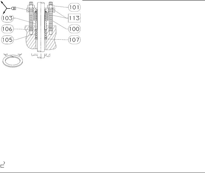
Figure 1. Typical ENVIRO-SEAL Packing System |
||
Introduction . . . . . . . . . . . . . . . . . . . . . . . . . . . . . . . . |
. 1 |
|
|
Scope of Manual . . . . . . . . . . . . . . . . . . . . . . . . . . . . . |
1 |
|
|
Valve/Actuator Shaft Coupler . . . . . . . . . . . . . . . . . . |
2 |
|
|
Description . . . . . . . . . . . . . . . . . . . . . . . . . . . . . . . . . |
2 |
|
|
Installation . . . . . . . . . . . . . . . . . . . . . . . . . . . . . . . . . . |
3 |
|
|
Removing the Actuator . . . . . . . . . . . . . . . . . . . . . . . |
3 |
|
|
Installing an ENVIRO-SEAL Packing System . . . . . . . |
4 |
|
|
Other Considerations . . . . . . . . . . . . . . . . . . . . . . . . |
11 |
|
|
Parts Ordering . . . . . . . . . . . . . . . . . . . . . . . . . . . . . . . |
13 |
|
|
Parts Kits . . . . . . . . . . . . . . . . . . . . . . . . . . . . . . . . . . . |
13 |
|
|
Retrofit Kits . . . . . . . . . . . . . . . . . . . . . . . . . . . . . . . . |
13 |
|
ROTARY |
Repair Kits . . . . . . . . . . . . . . . . . . . . . . . . . . . . . . . . . |
16 |
W5882-1 |
|
W9058-1 BUTTERFLY
Introduction
Scope of Manual
This instruction manual includes installation and parts information for Fisher ENVIRO-SEAL live-loaded packing systems (see figure 1). These systems are available for Fisher rotary valves with 12.7 through 88.9 mm (1/2 through 3-1/2 inch) shaft diameters. The system can be used with many rotary valves, as shown in tables 1 and 3. Refer to appropriate valve and actuator instruction manuals for necessary information relating to the disassembly and assembly of the valve and actuator. ENVIRO-SEAL packing systems utilize a Belleville (coned-disk) spring system.
Do not install, operate, or maintain the ENVIRO-SEAL packing system, valve, actuator or accessories without being fully trained and qualified in valve, actuator, and accessory installation, operation, and maintenance. To avoid personal injury or property damage, it is important to carefully read, understand, and follow all the contents of this manual, including all safety cautions and warnings. If you have any questions about these instructions, contact your Emerson Process Management sales office before proceeding.
www.Fisher.com

ENVIRO-SEAL System - Rotary Valves |
Instruction Manual |
November 2011 |
D101643X012 |
|
|
Table 1. Specifications |
|
Applicable Valve Designs
Fisher 8510B (single arrangements only), 8560 and 8532 eccentric disc control valves; A11, A31A, A31D and A41 control valves; V150, V200 and V300 Vee-Ballt control valves (Series B & Non-Series B(1)); V250 and V260 and BV500, CV500 and V500 eccentric plug rotary valves. Also see table 3.
Applicable Shaft Diameters
See table 3
Pressures and Temperatures(2)
See table 2
1.Refer to Fisher Vee-Ball V150, V200 & V300 instruction manual, for distinctions between Series B & Non-Series B.
2.The pressure/temperature limits in this manual, in the valve literature, and any applicable code or standard limitation should not be exceeded.
Table 2. Maximum Application Temperature and Pressure for 100 PPM Service
ENVIRO-SEAL PACKING MATERIAL |
MAXIMUM APPLICATION TEMPERATURE |
MAXIMUM APPLICATION |
|
||
_C |
_F |
PRESSURE |
|
||
|
|
||||
Single PTFE |
232 |
450 |
Not Restricted(1) |
|
|
Double PTFE(2) |
177 |
350 |
20.7 bar |
||
(300 Psi) |
|||||
|
|
|
|||
|
|
|
|
||
Graphite |
316 |
600 |
Not Restricted(1) |
||
1. For pressure ratings through CL600 of valves listed in this instruction manual.
2. These application conditions apply for double PTFE only in the valve types where double PTFE is available.
Valve/Actuator Shaft Coupler
To install an ENVIRO-SEAL packing system on an A11, A31A, A31D, or 8532 valve with a non-standard, non-Fisher produced actuator may require a special valve/actuator shaft coupler.
Table 10 contains a list of valve/actuator combinations and part numbers for the new coupler. If you are considering installation of an ENVIRO-SEAL packing system in another existing valve/actuator package, check table 10 to see if a new coupler is required.
In some cases, coupler replacement is not required when retrofitting valve/actuator combinations. Table 11 contains a list of valve/actuator combinations that can use existing couplers.
Description
Fisher packing systems are offered with exceptional sealing capabilities that you can easily install in existing valves or that you can purchase with new valves. These systems help you conserve valuable process fluid. The external live-loading provides a constant load over the life of the packing material, which reduces the need for packing box adjustment and maintenance.
The system design, coupled with very smooth shaft finishes and spring-loading of the packing, provides longer service with lower maintenance than many other designs.
2

Instruction Manual |
ENVIRO-SEAL System - Rotary Valves |
D101643X012 |
November 2011 |
|
|
Installation
Use these instructions to install ENVIRO-SEAL packing in valves that have standard packing, or when inspecting or replacing ENVIRO-SEAL packing.
If you are changing the packing system material from standard graphite to ENVIRO-SEAL graphite or ENVIRO-SEAL PTFE packing, the packing friction for ENVIRO-SEAL packing will be lower than it was for the standard packing. Therefore, no change should be needed in actuator sizing.
If you are changing the packing system material from standard PTFE to ENVIRO-SEAL graphite or ENVIRO-SEAL PTFE packing, the packing friction will increase. Contact your Emerson Process Management sales office to determine if your existing actuator will be large enough.

 WARNING
Always wear protective gloves, clothing and eyewear when performing any maintenance operations to avoid personal injury.
To avoid personal injury or property damage resulting from the sudden release of pressure, do not install the valve assembly where service conditions could exceed the limits given in this manual, the appropriate valve instruction manual, or the limits on the appropriate name plates. Use pressure relieving devices as required by government or accepted industry codes and good engineering practices.
Check with your process or safety engineer for any additional measures that must be taken to protect against process media.
If installing into an existing application, also refer to the WARNING at the beginning of the Removing the Actuator section in this instruction manual.
Removing the Actuator

 WARNING
Avoid personal injury from sudden release of process pressure or uncontrolled movement of parts. Before performing any maintenance operations:
D Do not remove the actuator from the valve while the valve is still pressurized.
DAlways wear protective gloves, clothing and eyewear when performing any maintenance operations to avoid personal injury.
DDisconnect any operating lines providing air pressure, electric power, or a control signal to the actuator. Be sure the actuator cannot suddenly open or close the valve.
DUse bypass valves or completely shut off the process to isolate the valve from process pressure. Relieve process pressure on both sides of the valve. Drain the process media from both sides of the valve.
D Vent the power actuator loading pressure and relieve any actuator spring precompression.
D Use lock-out procedures to be sure that the above measures stay in effect while you work on the equipment.
DThe valve packing box may contain process fluids that are pressurized, even when the valve has been removed from the pipeline. Process fluids may spray out under pressure when removing the packing hardware or packing rings, or when loosening the packing box pipe plug.
DCheck with your process or safety engineer for any additional measures that must be taken to protect against process media.
3

ENVIRO-SEAL System - Rotary Valves |
Instruction Manual |
November 2011 |
D101643X012 |
|
|
You must remove the actuator from the valve when you install ENVIRO-SEAL packing systems. To allow proper readjustment of the valve disc position, it is recommended that you remove the valve from the pipeline. Refer to appropriate valve and actuator instruction manuals.

 WARNING
If a spring-return actuator is used, be sure the actuator spring is resting on its travel stop. If something is obstructing shaft rotation, it is possible that disconnecting the shaft connector will allow the spring to force the actuator to the end of its rotation, resulting in possible personal injury or property damage. Refer to the appropriate valve and actuator instruction manuals to remove the actuator.
Installing an ENVIRO-SEAL Packing System
Note
When installing an ENVIRO-SEAL packing system into an insulated valve, do not cover the packing springs with insulation.
Note
The valve shaft surface condition is critical in obtaining a good seal. If the valve shaft surface is scratched, nicked, or worn, replace the valve shaft before installing the ENVIRO-SEAL Packing System.
Refer to the appropriate valve instruction manual to replace the valve shaft.
Key number locations are shown in figures 2 and 4 for Vee-Ball, eccentric plug, 8560, and A41 valves, and in figures 3 and 5 for A11, A31A, A31D and 8532 valves.
1.If you are installing an ENVIRO-SEAL packing system in an existing valve, remove existing packing nuts, packing flange, jam nuts, anti-blowout flange, packing follower, and any other external packing components from the valve body.
CAUTION
Because the valve shaft surface condition is critical in obtaining a good seal, caution must be used when removing existing internal packing parts. Do not scratch, nick or dent the valve shaft.
2.For A11, A31A, A31D and 8532 valves, remove the anti-blowout wire that surrounds the valve shaft.
3.For all valves, remove packing and all other internal components from the packing box.
4.Inspect the existing valve shaft. If necessary, replace the valve shaft. Refer to the appropriate valve instruction manual to replace the valve shaft.
4
Instruction Manual |
ENVIRO-SEAL System - Rotary Valves |
D101643X012 |
November 2011 |
|
|
Figure 2. Typical ENVIRO-SEAL Rotary Packing Arrangements with PTFE Packing for Fisher Vee-Ball, Eccentric Plug, A41, and 8560 Valves
SINGLE PTFE PACKING
STANDARD DEPTH BOX
14B0095-A
STACKING ORDER
PTFE PACKING RINGS
|
SINGLE PTFE PACKING |
DOUBLE PTFE PACKING WITH LEAKOFF |
SINGLE PTFE PACKING, OUTBOARD |
|
OPTIONAL DEEP PACKING BOX |
OPTIONAL DEEP PACKING BOX |
STANDARD DEPTH BOX |
|
V500 |
V500, CV500 |
8510B |
NOTES: |
|
|
|
|
APPLY LUBRICANT |
|
|
1 |
|
|
|
2  THESE TWO SURFACES MUST REMAIN PARALLEL AS YOU ALTERNATELY AND EVENLY TIGHTEN THE PACKING NUTS (KEY 101)
5

ENVIRO-SEAL System - Rotary Valves |
Instruction Manual |
November 2011 |
D101643X012 |
|
|
Note
ENVIRO-SEAL PTFE packing systems can be used in either vacuum or positive pressure service. It is not necessary to reverse ENVIRO-SEAL PTFE packing components in vacuum service.
Make sure that the Belleville springs are stacked properly and packing box parts are assembled in the correct order (see figure 6). Packing parts cannot function properly if the Belleville springs or other packing parts are not stacked correctly.
5. With the shaft in place in the valve, install the packing parts into the valve packing box.
Note
Be sure to install the packing rings in the sequence shown in figures 2 through 5.
a.Place one of the packing box rings (key 107) into the packing box. Be sure the packing box ring is properly seated. This does not apply to NPS 3, 4 and 6 CL600 A11 valves.
b.For PTFE packing, place an anti-extrusion washer (key 106) into the packing box and push it in until it rests next to the packing box ring (key 106 is not used with graphite packing).
Note
The graphite packing set has a carbon anti-extrusion ring on the top and bottom of the packing. These anti-extrusion rings are designed to have a slight interference fit on the shaft. The rings have a single fracture to allow the ring to be installed on the shaft. Additional fractures may develop while the valve is in service, however, these additional fractures will not affect the performance of the ENVIRO-SEAL packing.
c.Place the packing set (key 105) into the packing box. Refer to figure 3 or 5 for the proper orientation of the packing set.
d.For PTFE packing, place another anti-extrusion washer (key 106) into the packing box after the packing set (key 106 is not used with graphite packing).
e.Place the second packing box ring (key 107) into the packing box.
f.Locate the new spring pack assembly (key 103). Remove the O-ring and packing springs from the packing follower. Use the packing follower to press the packing components into the packing box. Remove the packing follower.
6.For A11, A31A, A31D and 8532 valves, install the anti-blowout wire (key 16) in the groove around the valve shaft.
7.Slide the packing follower from the new spring pack assembly over the valve shaft and the anti-blowout wire until it rests against the packing box ring.
8.For all valves, install the longer packing studs (key 100).
9.For A11, A31A, A31D and 8532 valves, install the new anti-blowout flange (key 10) over the valve shaft, packing studs, and packing follower. Secure the anti-blowout flange with the new jam nuts (key 17).
10.For all valves, install the spring pack assembly (key 103 or 104) which includes the Belleville springs, packing follower, and O-ring arranged as shown in figures 2 through 6. (The O-ring is a non-functional part and is used to retain the packing springs during assembly.)
6
 Loading...