


Instruction Manual |
L2 Controller |
D103032X012 |
September 2013 |
|
|
Fisherr L2 Liquid Level Controller
Contents |
|
Introduction . . . . . . . . . . . . . . . . . . . . . . . . . . . . . . . . . |
1 |
Scope of Manual . . . . . . . . . . . . . . . . . . . . . . . . . . . . . |
1 |
Description . . . . . . . . . . . . . . . . . . . . . . . . . . . . . . . . . |
3 |
Specifications . . . . . . . . . . . . . . . . . . . . . . . . . . . . . . . |
3 |
Education Services . . . . . . . . . . . . . . . . . . . . . . . . . . . |
3 |
Installation . . . . . . . . . . . . . . . . . . . . . . . . . . . . . . . . . . |
4 |
Attaching Vertical Displacer . . . . . . . . . . . . . . . . . . . |
4 |
Attaching Horizontal Displacer . . . . . . . . . . . . . . . . . |
4 |
Attaching the Sensor to the Vessel . . . . . . . . . . . . . |
5 |
Pressure Connections . . . . . . . . . . . . . . . . . . . . . . . . |
5 |
Vent . . . . . . . . . . . . . . . . . . . . . . . . . . . . . . . . . . . . . . . |
6 |
Changing Controller Action or Mode . . . . . . . . . . . . . |
6 |
Throttling and On/Off Controllers . . . . . . . . . . . . . . |
6 |
Snap Acting Controller . . . . . . . . . . . . . . . . . . . . . . . |
6 |
Span Adjustment . . . . . . . . . . . . . . . . . . . . . . . . . . . . . |
8 |
Preliminary Checks . . . . . . . . . . . . . . . . . . . . . . . . . . . |
8 |
Direct Acting Throttling Controllers . . . . . . . . . . . . |
9 |
Reverse Acting Throttling Controllers . . . . . . . . . . . |
9 |
Direct Acting On/Off and |
|
Snap Acting Controllers . . . . . . . . . . . . . . . . . . . . |
9 |
Reverse Acting On/Off and |
|
Snap Acting Controllers . . . . . . . . . . . . . . . . . . . . |
9 |
Principle of Operation . . . . . . . . . . . . . . . . . . . . . . . . |
10 |
Maintenance . . . . . . . . . . . . . . . . . . . . . . . . . . . . . . . . |
11 |
Removing the Controller From the Sensor . . . . . . . . |
11 |
Replacing the Sensor O Rings . . . . . . . . . . . . . . . . . |
11 |
Disassembly . . . . . . . . . . . . . . . . . . . . . . . . . . . . |
11 |
Assembly . . . . . . . . . . . . . . . . . . . . . . . . . . . . . . |
13 |
Replacing the Controller Relay . . . . . . . . . . . . . . . . |
13 |
Replacing the Controller Supply Filter . . . . . . . . . . |
13 |
Figure 1. Fisher L2 Liquid Level Controller
W8418 1
Related Documents . . . . . . . . . . . . . . . . . . . . . . . . . . 14
Parts Ordering . . . . . . . . . . . . . . . . . . . . . . . . . . . . . . . 14
Parts Kits . . . . . . . . . . . . . . . . . . . . . . . . . . . . . . . . . . . 14
Parts List . . . . . . . . . . . . . . . . . . . . . . . . . . . . . . . . . . . 14
Controller . . . . . . . . . . . . . . . . . . . . . . . . . . . . . . . . . 14
Sensor . . . . . . . . . . . . . . . . . . . . . . . . . . . . . . . . . . . . 16
Introduction
Scope of Manual
This instruction manual includes installation, adjustment, maintenance, and parts ordering information for the Fisher L2 liquid level controller.
Do not install, operate or maintain an L2 Liquid Level Controller without being fully trained and qualified in valve, actuator, and accessory installation, operation, and maintenance. To avoid personal injury or property damage, it is important to carefully read, understand, and follow all contents of this manual, including all safety cautions and warnings. If you have any questions about these instructions, contact your Emerson Process Management sales office before proceeding.
www.Fisher.com

L2 Controller |
|
|
Instruction Manual |
|||
September 2013 |
|
|
D103032X012 |
|||
|
|
|
|
|||
Table 1. Specifications |
|
|
||||
Available Configurations |
|
between 1.4 and 5.2 bar (20 and 50 psig) direct, and |
||||
Controller: Snap acting or throttling |
1.4 bar and 2.4 bar (20 and 35 psig) reverse |
|||||
|
||||||
Sensor: Displacer type liquid level sensor for |
Do not use supply pressure below 1.4 bar (20 psig) |
|||||
mounting to side of tank. Displacer travel is |
|
|||||
transmitted to controller by pivotal movement of |
Supply Medium |
|||||
displacer rod |
|
|
Air or natural gas(4) |
|||
|
|
|
|
|
||
Input Signal |
|
|
|
Steady State Air Consumption(5) |
||
Type: Liquid level or liquid to liquid interface |
||||||
Throttling Controller: ≤0.03 normal m3/hr (1.0 scfh) |
||||||
Level Change Required for Full Change in Output |
||||||
at 1.4 bar (20 psig) supply pressure |
||||||
Signal in 1.0 Specific Gravity Liquid, with 1.4 Bar (20 |
Snap Acting Controller: ≤0.03 normal m3/hr (1.0 |
|||||
Psig) Supply Pressure, Direct Action, and Standard 48 |
scfh) at 1.4 bar (20 psig) supply pressure or ≤0.04 |
|||||
x 305 mm (1 7/8 X 12 Inch) Vertical Displacer with |
normal m3/hr (1.5 scfh) at 2.4 bar (35 psig) supply |
|||||
Standard Lever Arm Length: |
|
pressure in tripped condition; air consumption |
||||
|
|
|
|
|
increases during trip |
|
Control |
|
Minimum Proportional |
Maximum Proportional |
|||
|
|
|||||
|
Band Level Change, mm |
Band Level Change, mm |
|
|||
Mode |
|
|
||||
|
|
(Inches)(1) |
(Inches)(1) |
Sensor to Vessel Connection |
||
|
|
|
||||
Throttling |
|
|
102 (4) |
305 (12) |
J 2 NPT threaded or J NPS 2 CL150 through 1500 |
|
|
|
|
|
|
||
On/Off |
|
|
127 (5) |
305 (12) |
||
|
|
slip on flange connection(6) |
||||
|
|
|
|
|
||
Snap acting |
|
|
13 (0.5) |
20 (0.8) |
|
|
|
|
|
|
|
Controller Connections |
|
|
|
|
|
|
||
Minimum Specific Gravity(2)
Throttling and On/Off Controllers: Minimum specific gravity, or specific gravity differential for interface applications, is 0.1 (see footnote 3)
Snap Acting Controllers: Minimum specific gravity, or specific gravity differential for interface applications, is 0.1
Supply: 1/4 NPT internal located on the bottom of the case
Output: 1/4 NPT internal located on the top of the case
Case Vent: 1/4 NPT internal with vent screen assembly located on the back of the case
Standard Displacer Size
Output Signal
Pneumatic J on off or J proportional pressure signal
Ranges:
Throttling: J 0.2 to 1.0 bar (3 to 15 psig) or J 0.4 to 2.0 bar (6 to 30 psig)
On/Off: 0 (off) or full supply pressure (on)
Action: Field reversible between direct (increasing level increases output signal) and reverse (increasing level decreases output signal)
Supply Pressure Requirements
Throttling and On/Off Controller
Throttling: 1.4 bar for 0.2 to 1.0 bar output signal (20 psig for 3 to 15 psig output signal) and 2.4 bar for 0.4 to 2.0 bar output signal (35 psig for 6 to 30 psig output signal)
On/Off: Any desired pressure between 1.4 and 3.4 bar (20 and 50 psig).
Snap Acting Controller: Any desired pressure
48 x 305 mm, 541 cm3 (1 7/8 x 12 inches, 33 in3)
Maximum Displacer Insertion Length(7)
Standard lever arm length plus one 6 inch extension, horizontal or vertical
Displacer Material and Maximum Sensor Working
Pressure(8)
PVC Displacer: Consistent with CL1500 pressure temperature ratings per ASME B16.34 up to maximum pressure of 258 bar (3750 psig)
For PED (97/23/EC) maximum pressure limited to 200 bar (2900 psig)
S31603 SST Displacer: CL600 pressure temperature ratings per ASME B16.34 up to maximum pressure of 99.3 bar (1440 psig)
Note: For slip on flange connection, maximum sensor working pressure must be consistent with the flange ratings
-Continued-
2
Instruction Manual |
L2 Controller |
D103032X012 |
September 2013 |
|
|
Table 1. Specifications (continued)
Displacer Material and Sensor Temperature
Limits(8)
PVC Displacer -29 to 79_C (-20 to 175_F)
S31603 SST Displacer: -40 to 204_C (-40 to 400_F)
Operative Ambient Temperature Limits(8)
Controller: -29 to 71_C (-20 to 160_F)
Standard Supply, and Output Pressure Gauge
Indications
Triple scale gauges in 0 to 60 psig/0 to 0.4 MPa/0 to 4.0 bar
Hazardous Area Classification
Complies with the requirements of ATEX Group II Category 2 Gas and Dust
Declaration of SEP
Fisher Controls International LLC declares this product to be in compliance with Article 3 paragraph 3 of the Pressure Equipment Directive (PED) 97 / 23 / EC. It was designed and manufactured in accordance with Sound Engineering Practice (SEP) and cannot bear the CE marking related to PED compliance.
However, the product may bear the CE marking to indicate compliance with other applicable European Community Directives.
NOTE: Specialized instrument terms are defined in ISA Standard 51.1 - Process Instrument Terminology.
1.Any deviation from the standard construction described in the input signal specification above requires special displacer sizing considerations. Contact your Emerson Process Management sales office for information.
2.Depends on float rod/displacer orientation and length. Contact your Emerson Process Management sales office for further information.
3.Minimum specific gravity differential with standard displacer is 0.4. Minimum specific gravity differential of 0.1 is possible with special displacer, consult your Emerson Process Management sales office for displacer sizing information.
4.This product can be used with natural gas as the supply medium. Natural gas should contain no more than 20 ppm of H2S
5.Normal m3/hr—Normal cubic meters per hour (0_C and 1.01325 bar, absolute) Scfh—Standard cubic feet per hour (60_F and 14.7 psia).
6.Converting from a threaded NPT connection to a flange connection is to be done by the end-user. Refer to Converting a Threaded NPT Connection to a Flange Connection instruction Manual Supplement (D103277X012), available at www.Fisher.com or from your Emerson Process Management sales office.
7.Standard lever arm length.
8.The pressure and temperature limits in this document and any applicable code limitations should not be exceeded.
Description
The rugged L2 liquid level controllers use a displacer type sensor (see figure 1) to detect liquid level or the interface of two liquids of different specific gravities.
These controllers use a single four mode relay to provide the applicable control and action. The device delivers a pneumatic output signal to a control/dump valve.
Unless otherwise noted, all NACE references are to NACE MR0175 2002.
Specifications
Specifications for the controller and sensor are listed in table 1.
Educational Services
For information on available courses for L2 Liquid Level Controllers, as well as a variety of other products, contact:
Emerson Process Management Educational Services, Registration P.O. Box 190; 301 S. 1st Ave. Marshalltown, IA 50158-2823 Phone: 800-338-8158 or
Phone: 641-754-3771 FAX: 641-754-3431
e mail: education@emerson.com
3

L2 Controller |
Instruction Manual |
September 2013 |
D103032X012 |
|
|
Installation

 WARNING
Always wear protective clothing, gloves, and eyewear when performing any installation operations to avoid personal injury.
To avoid personal injury or property damage caused by the sudden release of process fluid, be certain the service conditions do not exceed the sensor pressure limits. Use pressure limiting or pressure relieving devices to prevent service conditions from exceeding these limits.
Personal injury or property damage may result from fire or explosion if natural gas is used as the supply medium and appropriate preventive measures are not taken. Preventive measures may include, but are not limited to, one or more of the following: Remote venting of the unit, re evaluating the hazardous area classification, ensuring adequate ventilation, and the removal of any ignition sources. For information on remote venting of this controller,
refer to page 6.
Check with your process or safety engineer for any additional measures that must be taken to protect against process media.
If installing this into an existing application, also refer to the WARNING at the beginning of the Maintenance section of this instruction manual.
CAUTION
If the L2 level controller is installed on a vessel that is to be shipped to a different location (e.g. skid mounted units), remove the displacer and displacer rod extensions before shipment. Failure to do so could result in damage to the displacer rod due to vibration and impact loading during shipment. After the vessel is installed at its final location, reassemble the displacer and displacer rod extension.
1.Be sure there are no obstructions inside the tank that will interfere with displacer installation or operation.
2.Provide the appropriate connection in the tank wall to match the sensor connection. Locate the tank wall connection such that the displacer will be at the desired control level.
Attaching a Vertical Displacer
Refer to figure 7 for part locations.
1.Thread jam nut (key 68) all the way onto the threaded portion of the universal joint assembly (key 69).
2.Thread the displacer (key 81) all the way onto the threaded portion of the universal joint assembly.
3.Tighten the jam nut (key 63) against the displacer (key 81).
Attaching a Horizontal Displacer
Refer to figure 7 for part locations.
1.Thread the displacer (key 81) all the way onto the displacer rod (key 64) or extension (key 82).
2.Tighten the jam nut (key 63) against the displacer (key 81).
4
Instruction Manual |
L2 Controller |
D103032X012 |
September 2013 |
|
|
Attaching the Sensor to the Vessel
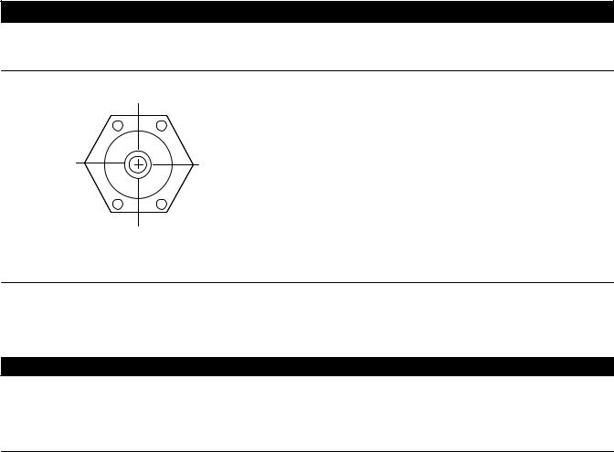
Insert the displacer end of the controller sensor assembly into the tank connection, and screw the sensor threads into the tank connection. Tighten sufficiently to seal the threads. If necessary, loosen or tighten slightly to obtain the orientation shown in figure 2. Make sure that the controller case is level.
CAUTION
Do not pick up the controller/sensor by lifting the displacer rod (key 64). This action could place excessive stress on the displacer rod and cause the unit to malfunction.
Figure 2. Sensor Orientation
CORRECT CONTROLLER MOUNTING
HOLE ORIENTATION WHEN MOUNTED ON VESSEL
A6639
Pressure Connections

 WARNING
Personal injury or property damage may occur from an uncontrolled process if the supply medium is not clean, dry, oil free air, or non corrosive gas. While use and regular maintenance of a filter that removes particles larger than 40 micrometers in diameter will suffice in most applications, check with an Emerson Process Management field office and industry instrument air quality standards for use with corrosive air or if you are unsure about the proper amount or method of air filtration or filter maintenance.
1.Provide a source of clean, dry air that meets the requirements of ISA Standard 7.0.01 as the operating medium. Refer to table 1 to determine supply pressure.
2.Connect the supply pressure to the 1/4 NPT internal connection on the bottom of the controller case.
3.Connect the output signal line to the equipment being operated and to the 1/4 NPT output connection on the top of the controller case.
5
 Loading...