


Quick Start Guide |
DVC6200 Digital Valve Controllers |
D103556X012 |
January 2014 |
|
|
Fisherr FIELDVUE™ DVC6200 Series Digital Valve
Controllers
Contents
Before You Begin . . . . . . . . . . . . . . . . . . . . . . . . . . . . . . . . . . . . . . |
2 |
Step 1. Install the DVC6200 on the Valve . . . . . . . . . . . . . . . . . . . 3 Step 2. Connect the Pneumatic Tubing . . . . . . . . . . . . . . . . . . . 15 Step 3. Connect the Electrical Wires . . . . . . . . . . . . . . . . . . . . . . 19 Step 4. Configure the DVC6200 . . . . . . . . . . . . . . . . . . . . . . . . . 29
Special Instructions for Safety Instrumented Systems Hazardous Area Approvals and Special Instructions for ÓSafe Use”and Installations in Hazardous Locations
. . . . . . . 31
. . . . . . . 39
W9713
This quick start guide provides installation and initial setup information for DVC6200 Series digital valve controllers
SIS
www.Fisher.com
DVC6200 Digital Valve Controllers |
Quick Start Guide |
|
January 2014 |
D103556X012 |
|
|
|
|
|
|
|
|
SIS |
|
Before You Begin
Do not install, operate, or maintain a DVC6200 digital valve controller without being fully trained and qualified in valve, actuator, and accessory installation, operation, and maintenance. To avoid personal injury or property damage, it is important to carefully read, understand, and follow all contents of this quick start guide, including all safety cautions and warnings. Refer to Hazardous Area Approvals and Special Instructions for “Safe Use” and Installations in Hazardous Locations, on page 39, for approval specific safe use information. If you have any
questions about these instructions, contact your Emerson Process Management sales office before proceeding.

 WARNING
Avoid personal injury or property damage from sudden release of process pressure or bursting of parts. Before proceeding with any Installation procedures:
D Always wear protective clothing, gloves, and eyewear to prevent personal injury or property damage.
D Do not remove the actuator from the valve while the valve is still pressurized.
D Disconnect any operating lines providing air pressure, electric power, or a control signal to the actuator. Be sure the actuator cannot suddenly open or close the valve.
D Use bypass valves or completely shut off the process to isolate the valve from process pressure. Relieve process pressure from both sides of the valve.
D Use lock out procedures to be sure that the above measures stay in effect while you work on the equipment.
D Check with your process or safety engineer for any additional measures that must be taken to protect against process media.
D Vent the pneumatic actuator loading pressure and relieve any actuator spring precompression so the actuator is not applying force to the valve stem; this will allow for the safe removal of the stem connector.

 WARNING
To avoid static discharge from the plastic cover when flammable gases or dust are present, do not rub or clean the cover with solvents. To do so could result in a spark that may cause the flammable gases or dust to explode, resulting in personal injury or property damage. Clean with a mild detergent and water only.
For information on installation and usage of DVC6200 Series digital valve controllers, visit the Fisher channel on YouTube and search for FIELDVUE.
http://www.youtube.com/user/FisherControlValve
2
Quick Start Guide |
DVC6200 Digital Valve Controllers |
|
|
D103556X012 |
|
January 2014 |
|
|
|
|
|
|
|
|
|
|
|
SIS |
|
Step 1—Install the DVC6200 on the Valve
If ordered as part of a control valve assembly, the factory will mount the digital valve controller on the actuator and calibrate the instrument. If you purchased the digital valve controller separately, you will need a mounting kit. The following procedures are general guidelines. See the instructions that come with the mounting kit for detailed information on mounting the digital valve controller to a specific actuator model.
CAUTION
The magnet assembly material has been specifically chosen to provide a long term stable magnetic field.
However, as with any magnet, care must be taken when handling the magnet assembly. Another high powered magnet placed in close proximity (less than 25 mm) can cause permanent damage. Potential sources of damaging equipment include, but are not limited to: transformers, DC motors, stacking magnet assemblies.
General Guidelines for use of High Power Magnets with Positioners
Use of high power magnets in close proximity to any positioner which is operating a process should be avoided. Regardless of the positioner model, high power magnets can affect the positioner’s ability to control the valve. Technicians should avoid the use of high power magnets in close proximity with any positioner.
Use of Magnetic Tools with the DVC6200
D Magnetic Tip Screw Drivers – Magnetic tip screw drivers can be used to work on the DVC6200. However, they should not be brought in close proximity to the magnet assembly (located at the back of the instrument) during process operations.
D Calibrator Strap Magnets – These are high power magnets used to hold 4-20 mA calibrators. Normally, these calibrators would not be used while an instrument is controlling the process. High power magnets should be kept at least 15 cm (6 inches) from the DVC6200.
Note
D The mounting instructions also apply to the DVC6215 remote mount feedback unit.
D As a general rule, do not use less than 60% of the magnet assembly travel range for full travel measurement. Performance will decrease as the assembly is increasingly subranged.
D The linear magnet assemblies have a valid travel range indicated by arrows molded into the piece. This means that the hall sensor (the center point of the channel on the back of the DVC6200 housing) has to remain within this range throughout the entire valve travel. The linear magnet assemblies are symmetrical. Either end may be up.
D The magnet assembly may be referred to as a magnetic array in user interface tools.
D Mounting the instrument vertically, with the vent at the bottom of the assembly, or horizontally, with the vent pointing down, is recommended to allow drainage of moisture that may be introduced via the instrument air supply.
For sliding stem linear actuators up to 210 mm (8.25 inches) travel proceed to page 4 For sliding stem linear actuators over 210 mm (8.25 inches) travel proceed to page 6 For GX actuators proceed to page 7
For Fisher rotary actuators proceed to page 11
For quarter turn rotary actuators proceed to page 12
3
DVC6200 Digital Valve Controllers |
Quick Start Guide |
January 2014 |
D103556X012 |
|
|
Sliding Stem Linear Actuators Up to 210 mm (8.25 inches) Travel
1.Isolate the control valve from the process line pressure and release pressure from both sides of the valve body. Shut off all pressure lines to the actuator, releasing all pressure from the actuator. Use lock out procedures to be sure that the above measures stay in effect while you work on the equipment.
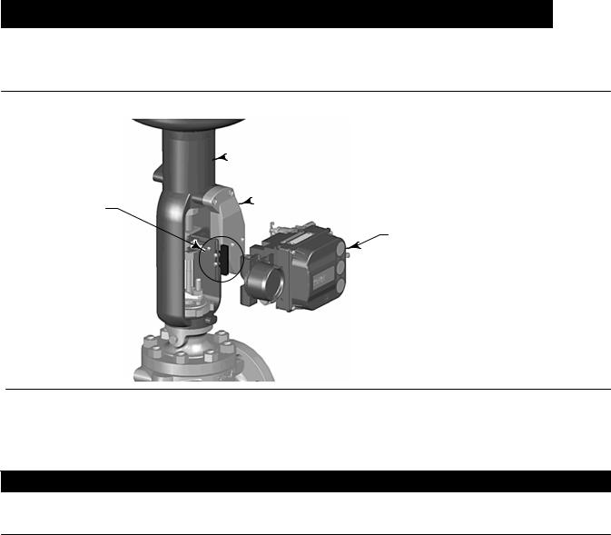
Figure 1. Mounting Parts for Sliding Stem Actuator with up to 210 mm (8.25 inches) Travel

 ACTUATOR
 MOUNTING
FEEDBACK BRACKET BRACKET
AND MAGNET ASSEMBLY
DIGITAL VALVE
CONTROLLER
X0381-1
2.Attach the mounting bracket to the actuator.
3.Loosely attach the feedback pieces and magnet assembly to the valve stem connector. Do not tighten the fasteners because fine adjustment is required.
CAUTION
Do not install a magnet assembly that is shorter than the physical travel of the actuator. Loss of control will result from the magnet assembly moving outside the range of the index mark in the feedback slot of the DVC6200 housing.
4.Using the alignment template (supplied with the mounting kit), position the magnet assembly inside the retaining slot.
5.Align the magnet assembly as follows:
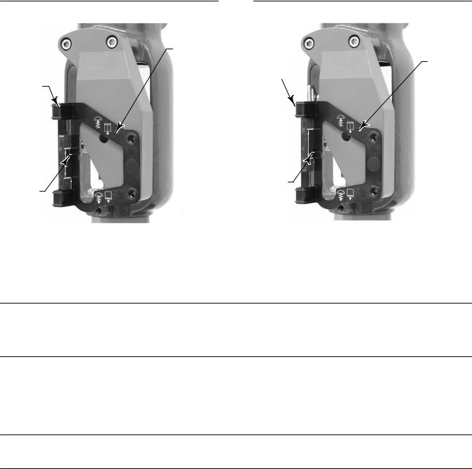
D For air to open actuators (e.g. Fisher 667) vertically align the magnet assembly so that the center line of the alignment template is lined up as close as possible with the upper extreme of the valid travel range on the magnet assembly. The magnet assembly should be positioned so that the index mark in the feedback slot of the DVC6200 housing is within the valid range on the magnet assembly throughout the range of travel. See figure 2.
4
Quick Start Guide |
DVC6200 Digital Valve Controllers |
D103556X012 |
January 2014 |
|
|
D For air to close actuators (e.g. Fisher 657) vertically align the magnet assembly so that the center line of the alignment template is lined up as close as possible with the lower extreme of the valid travel range on the magnet assembly. The magnet assembly should be positioned so that the index mark in the feedback slot of the DVC6200 housing is within the valid range on the magnet assembly throughout the range of travel. See figure 3.
Figure 2. Air to Open Magnet Assembly Alignment |
Figure 3. Air to Close Magnet Assembly Alignment |
|||
ALIGNMENT |
|
|
|
|
TEMPLATE |
|
|
|
ALIGNMENT |
|
|
|
|
|
|
RETAINING |
TEMPLATE |
||
RETAINING |
SLOT |
|
|
|
|
|
|||
SLOT |
|
|
|
|
INDEX
INDEX MARK
MARK
W9718 |
|
W9719 |
|
|
|
6. Tighten the fasteners and remove the alignment template.
Note
Use a flat end hex key to tighten the mounting assembly fasteners to a torque of 2.37 N•m (21 lbf•in) for 4 mm screws, and
5.08 N•m (45 lbf•in) for 5 mm screws. While tightening the fasteners using the hex key should be sufficient, blue (medium) thread locker may be used for additional security.
7.Mount the digital valve controller to the mounting bracket, using the mounting bolts.
8.Check for clearance between the magnet assembly and the DVC6200 feedback slot.
Note
Ensure that there is clearance between the magnet assembly and the DVC6200 housing slot throughout the full range of travel.
9.For remote mount applications, proceed to page 13 for DVC6205 base unit mounting. Otherwise, proceed to Step 2—Connect the Pneumatic Tubing on page 15.
5
DVC6200 Digital Valve Controllers |
Quick Start Guide |
January 2014 |
D103556X012 |
|
|
Sliding Stem Linear Actuators Over 210 mm (8.25 inches) Travel
1.Isolate the control valve from the process line pressure and release pressure from both sides of the valve body. Shut off all pressure lines to the pneumatic actuator, releasing all pressure from the actuator. Use lock out procedures to be sure that the above measures stay in effect while working on the equipment.
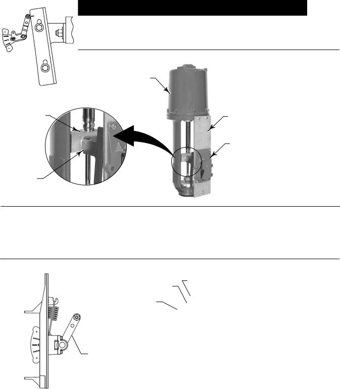
Figure 4. Mounting on Sliding Stem (Linear) Actuators over 210 mm (8.25 Inches) Travel
ACTUATOR
VALVE STEM |
MOUNTING ADAPTOR |
|
CONNECTOR |
||
|
LONG STROKE MOUNTING KIT (DVC6200 NOT SHOWN)
CAM
W9709
2.Install the cam to the valve stem connector as described in the instructions included with the mounting kit.
3.Install the mounting adaptor to the actuator.
4.Attach the digital valve controller and mounting kit assembly to the mounting adaptor. The roller on the digital valve controller feedback arm will contact the actuator cam as it is being attached.
Figure 5. Roller Arm Variation used for Sliding Stem (Linear) Actuators over 210 mm (8.25 Inches) Travel
CAM
CAM/ROLLER
POSITION MARK
ROLLER ARM
|
ROLLER |
|
ARM |
|
E1543 |
E1229 |
ACTUATOR IS FULLY EXTENDED |
|
|
5.For remote mount applications, proceed to page 13 for DVC6205 base unit mounting. Otherwise, proceed to Step 2—Connect the Pneumatic Tubing on page 15.
6
Quick Start Guide |
DVC6200 Digital Valve Controllers |
D103556X012 |
January 2014 |
|
|
Fisher GX Actuators
1.Isolate the control valve from the process line pressure and release pressure from both sides of the valve body. Shut off all pressure lines to the actuator, releasing all pressure from the actuator. Use lock out procedures to be sure that the above measures stay in effect while you work on the equipment.
2.The DVC6200 digital valve controller mounts directly on the GX actuator without the need for a mounting bracket. Make sure you have the correct DVC6200 housing, identified by mounting bolt slots (not holes) below the output press sure port.
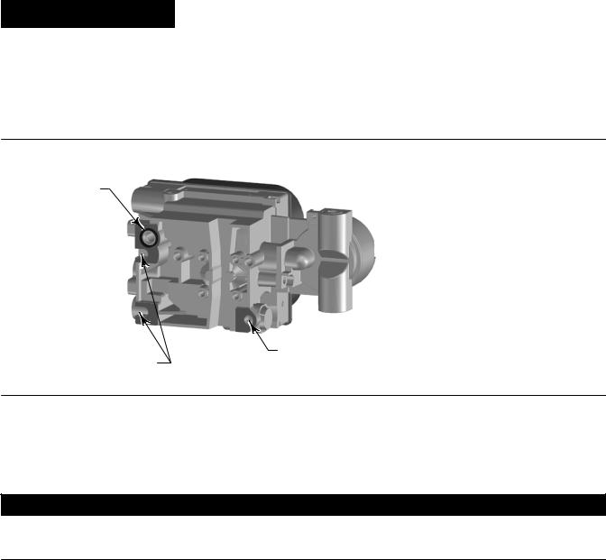
Figure 6. Housing Configuration for Fisher GX Actuators
INTEGRAL OUTPUT
PRESSURE PORT
HOLE FOR
SLOTS FOR MOUNTING BOLT
MOUNTING BOLTS
W9704
3.Identify the yoke side to mount the DVC6200 digital valve controller based on the actuator fail mode. Refer to the GX Control Valve and Actuator System instruction manual (D103175X012).
4.Loosely attach the feedback pieces and magnet assembly to the valve stem connector. Do not tighten the fasteners because fine adjustment is required.
CAUTION
Do not install a magnet assembly that is shorter than the physical travel of the actuator. Loss of control will result from the magnet assembly moving outside the range of the index mark in the feedback slot of the DVC6200 housing.
5.Using the alignment template (supplied with the mounting kit), position the feedback assembly inside the retaining slot.
6.Align the magnet assembly as follows:
For air to open GX actuators
Vertically align the magnet assembly so that the center line of the alignment template is lined up as close as possible with the upper extreme of the valid travel range on the magnet assembly. The magnet assembly should be positioned so that the index mark in the feedback slot of the DVC6200 housing is within the valid range on the magnet assembly throughout the range of travel. See figure 7.
7

DVC6200 Digital Valve Controllers |
Quick Start Guide |
January 2014 |
D103556X012 |
|
|
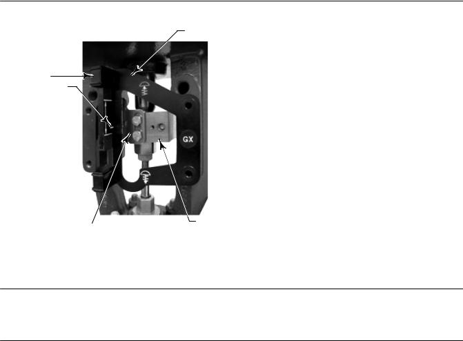
Figure 7. Air to Open Fisher GX Magnet Assembly Alignment
ALIGNMENT TEMPLATE
RETAINING
SLOT 
INDEX
MARK
|
|
FEEDBACK PIECES |
VALVE STEM |
W9218 |
|
|
CONNECTOR |
|
|
|
|
7. Tighten the fasteners and remove the alignment template.
Note
Use a flat end hex key to tighten the mounting assembly fasteners to a torque of 2.37 N•m (21 lbf•in) for 4 mm screws, and
5.08 N•m (45 lbf•in) for 5 mm screws. While tightening the fasteners using the hex key should be sufficient, blue (medium) thread locker may be used for additional security.
8.Remove the plug (R1/8) from the back of the DVC6200 housing. This pneumatic output port on the DVC6200 lines up with the integral GX actuator pneumatic port. See figure 8.
Figure 8. Modifications for Fisher GX Actuator; Air to Open Construction Only
INSTALL O RING
INSTALL
1/4 NPT PLUG
REMOVE R1/8 PLUG
W9707
8
Quick Start Guide |
DVC6200 Digital Valve Controllers |
D103556X012 |
January 2014 |
|
|
9. Install the plug (1/4 NPT, included in the mounting kit) to the external output pneumatic port A.
10.Using a 5 mm hex wrench, attach the digital valve controller to the GX actuator mounting pad on the side that has the open pneumatic port. Be sure to place the O ring between the digital valve controller's pneumatic output and the actuator mounting pad. Pneumatic tubing is not required because the air passages are internal to the actuator.
11.Check for clearance between the magnet assembly and the DVC6200 feedback slot.
12.If not already installed, install a vent in the port on the upper diaphragm casing's air supply connection on the actuator yoke leg.
13.For remote mount applications, proceed to page 13 for DVC6205 base unit mounting. Otherwise, proceed to Step 2—Connect the Pneumatic Tubing on page 15.
For air to close GX actuators
Vertically align the magnet assembly so that the center line of the alignment template is lined up as close as possible with the lower extreme of the valid travel range on the magnet assembly. The magnet assembly should be positioned so that the index mark on the pole pieces (back of the DVC6200 housing) is within the valid range on the magnet assembly throughout the range of travel. See figure 9.
Figure 9. Air to Close Fisher GX Magnet Assembly Alignment
ALIGNMENT
TEMPLATE
RETAINING
SLOT
INDEX MARK
|
|
FEEDBACK PIECES |
VALVE STEM |
|
|
||
W9219 |
CONNECTOR |
||
|
|
|
|
7. Tighten the fasteners and remove the alignment template.
Note
Use a flat end hex key to tighten the mounting assembly fasteners to a torque of 2.37 N•m (21 lbf•in) for 4 mm screws, and
5.08 N•m (45 lbf•in) for 5 mm screws. While tightening the fasteners using the hex key should be sufficient, blue (medium) thread locker may be used for additional security.
9

DVC6200 Digital Valve Controllers |
Quick Start Guide |
January 2014 |
D103556X012 |
|
|
8.Using a 5 mm hex wrench, attach the digital valve controller to the GX actuator mounting pad.
9.Check for clearance between the magnet assembly and the DVC6200 feedback slot.
10.Install tubing between the actuator casing and the appropriate DVC6200 pneumatic output port.
11.If not already installed, install a vent in the port on the lower diaphragm casing.
12.For remote mount applications, proceed to page 13 for DVC6205 base unit mounting. Otherwise, proceed to Step 2—Connect the Pneumatic Tubing on page 15.
Note
When field converting a GX actuator from air-to-close to air-to-open (or vice versa), you will need to change the plugs for the pneumatic passages in the DVC6200 housing.
D To convert to air-to-open, remove the R1/8 pneumatic plug on the back of the DVC6200 housing and install an O ring. Plug the external pneumatic output with a 1/4 NPT plug. Refer to figure 8.
D To convert to air-to-close, remove the external pneumatic plug. Install an R1/8 plug on the back of the DVC6200 housing. Install tubing between the pneumatic output connection of the DVC6200 to the pneumatic port on top of the actuator casing.
10
Quick Start Guide |
DVC6200 Digital Valve Controllers |
D103556X012 |
January 2014 |
|
|
Fisher Rotary Actuators
1.Isolate the control valve from the process line pressure and release pressure from both sides of the valve body. Shut off all pressure lines to the pneumatic actuator, releasing all pressure from the actuator. Use lock out procedures to be sure that the above measures stay in effect while working on the equipment.
Figure 10. Mounting on Rotary Actuators
ROTARY MOUNTING KIT (DVC6200 NOT SHOWN)
W9708
2.Verify that the appropriate cam is installed on the actuator as described in the instructions included with the mounting kit.
Figure 11. Rotary Actuator Mounting Variations
ROLLER ARM |
ROLLER ARM |
ROLLER ARM |
2052 SIZE 2 AND 3 |
|
|
1051/1052 SIZE 40-70 |
|
1051 SIZE 33 |
SIZE 1061 SIZE 30-100 |
2052 SIZE 1 |
1052 SIZE 20-33 |
NOTE THE DIFFERENCE IN THE SHAPE AND LENGTH OF THE ROLLER ARM
E1229
3.Mount the DVC6200 on the actuator as follows:
D If required, a mounting adaptor is included in the mounting kit. Attach the adaptor to the digital valve controller, then attach the digital valve controller assembly to the actuator. The roller on the digital valve controller feedback arm will contact the actuator cam as it is being attached.
D If no mounting adaptor is required, attach the digital valve controller and mounting kit assembly to the actuator. The roller on the digital valve controller feedback arm will contact the actuator cam as it is being attached.
4.For remote mount applications, proceed to page 13 for DVC6205 base unit mounting. Otherwise, proceed to Step 2—Connect the Pneumatic Tubing on page 15.
11
DVC6200 Digital Valve Controllers |
Quick Start Guide |
January 2014 |
D103556X012 |
|
|
Quarter Turn Rotary Actuators
The DVC6200 digital valve controller can be mounted to any quarter turn rotary actuator, as well as those that comply with the NAMUR guidelines. A mounting bracket and associated hardware are required. Refer to figure 12.
1.Isolate the control valve from the process line pressure and release pressure from both sides of the valve body. Shut off all pressure lines to the actuator, releasing all pressure from the actuator. Use lock out procedures to be sure that the above measures stay in effect while you work on the equipment.
Figure 12. Mounting on Quarter Turn Actuators
W9715 |
|
M6 MOUNTING BOLTS (4) |
|
||
|
|
|
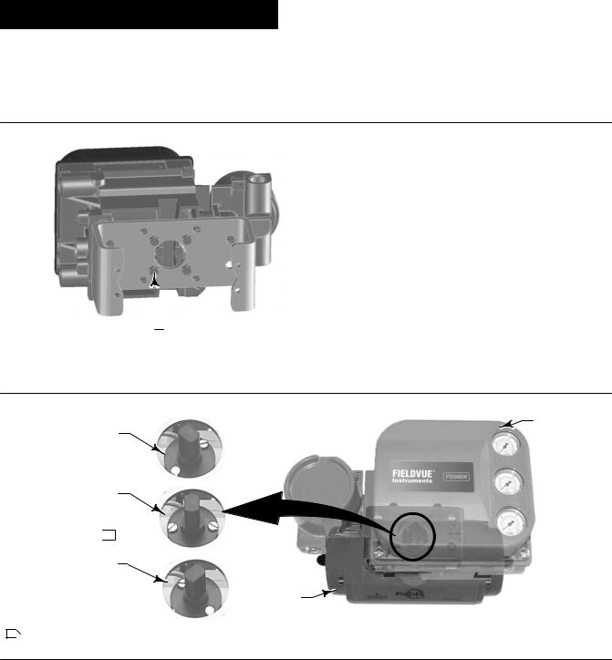
2.Attach the magnet assembly to the actuator shaft. At mid travel, the flats on the magnet assembly should be approximately parallel to the channel on the back of the DVC6200 housing, as shown in figure 13.
Figure 13. Magnet Assembly Orientation on Quarter Turn Actuators
DVC6200
ORIENTATION
AT ONE TRAVEL EXTREME
ORIENTATION AT MID TRAVEL (FLATS PARALLEL TO DVC6200 CHANNEL)  1
1
ORIENTATION
AT THE OTHER
TRAVEL EXTREME
ACTUATOR
W9700
1Ã THIS EXAMPLE SHOWS AN ACTUATOR WITH 90_TRAVEL. ON AN ACTUATOR THAT HAS LESS THAN 90_TRAVEL THE MAGNET ASSEMBLY MAY NOT BE PARALLEL AT THE MID-TRAVEL POINT. TO VERIFY THE MAGNET ASSEMBLY POSITION IS IN WORKING RANGE, CONFIRM TRAVEL COUNTS ARE WITHIN THE EXPECTED RANGE OF 175-3800 USING VALVELINK SOFTWARE OR A FIELD COMMUNICATOR.
3.Install the mounting bracket on the actuator.
4.Attach the digital valve controller to the mounting bracket using the 4 mounting bolts, as shown in figure 12.
5.Check for clearance between the magnet assembly and the DVC6200 feedback slot.
6.For remote mount applications, proceed to page 13 for DVC6205 base unit mounting. Otherwise, proceed to Step 2—Connect the Pneumatic Tubing on page 15.
12
Quick Start Guide |
DVC6200 Digital Valve Controllers |
D103556X012 |
January 2014 |
|
|
DVC6205 Remote Mount Base Unit Mounting
For remote mounted digital valve controllers, the DVC6205 base unit ships separately from the control valve and does not include tubing, fittings or wiring.
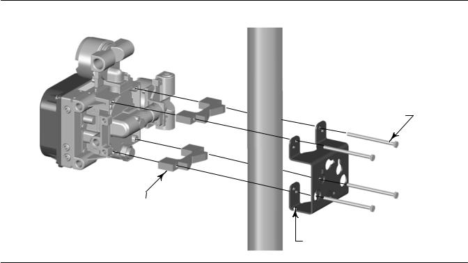
Pipestand Mounting
1.Position a standoff on the back of the base unit.
2.Using two 101.6 mm (4 inch) 1/4 20 hex head screws loosely attach the base unit to the pipestand with the mounting bracket.
3.Position the second standoff, then using the remaining 101.6 mm (4 inch) hex head screws, securely fasten the base unit to the pipe stand.
4.Tighten all screws.
5.Proceed to Step 2—Connect the Pneumatic Tubing on page 15.
Figure 14. FIELDVUE DVC6205 Pipestand Mounting
4 INCH 1/4 20 HEX HEAD SCREW
STANDOFF
MOUNTING BRACKET
X0437
13
DVC6200 Digital Valve Controllers |
Quick Start Guide |
January 2014 |
D103556X012 |
|
|
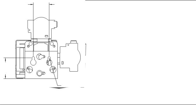
Wall Mounting
1.Install the wall mounting screws by using the mounting bracket as a template.
2.Install the mounting bracket to the back of the base unit using the spacers and screws provided in the mounting kit.
3.Slide the assembly on the wall mounting screws and tighten.
4.Proceed to Step 2—Connect the Pneumatic Tubing on page 15.
Figure 15. FIELDVUE DVC6205 Wall Mounting
57
(2.25)
SPACER
1 INCH 1/4 20 HEX HEAD SCREW
|
|
72 |
|
|
(2.82) |
X0428 |
MOUNTING |
|
|
10C1796 A |
|
|
BRACKET |
|
|
|
2 MOUNTING HOLES
O 8.6/0.34
14
Quick Start Guide |
DVC6200 Digital Valve Controllers |
|
|
D103556X012 |
|
January 2014 |
|
|
|
|
|
|
|
|
|
|
|
SIS |
|
Step 2—Connect the Pneumatic Tubing
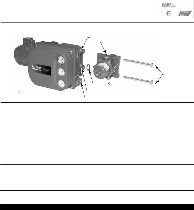
Figure 16. Integral Mounting of a Fisher 67CFR Regulator on a FIELDVUE DVC6200 Digital Valve Controller
OUTPUT A (1/4 NPT) 67CFR
CAP SCREWS
|
|
|
|
|
|
|
|
NOTE: |
|
|
|
O RING 1 |
|
||
|
|
|
|
||||
|
|
|
|
|
|
||
|
SUPPLY CONNECTION (1/4 NPT) |
||||||
1 APPLY LUBRICANT |
|
||||||
|
|
|
|
|
|
||
|
|
|
OUTPUT B (1/4 NPT) |
||||
|
|
|
|||||
W9702-1
1.Connect the DVC6200 pneumatic output to the actuator input using at least 10 mm (3/8inch) diameter tubing.
D When using a singleacting direct digital valve controller (relay A or C) on a singleacting actuator, connect OUTPUT A to the actuator pneumatic input.
D When using a singleacting reverse digital valve controller (relay B) on a singleacting actuator, connect OUTPUT B to the actuator diaphragm casing.
D When using a doubleacting digital valve controller (relay A) on a doubleacting actuator, connect OUTPUT A and OUTPUT B to the appropriate actuator pneumatic input. With no input current to the DVC6200, OUTPUT A is at zero pressure and OUTPUT B is at full supply pressure when the relay is properly adjusted.
Note
To have the actuator stem extend from the cylinder with increasing input signal, connect OUTPUT A to the actuator cylinder connection farthest from the actuator stem. Connect OUTPUT B to the cylinder connection closest to the actuator stem. To have the actuator stem retract into the cylinder with increasing input signal, connect OUTPUT A to the actuator cylinder connection closest to the actuator stem. Connect OUTPUT B to the cylinder connection farthest from the actuator stem.

 WARNING
Supply pressure must be clean, dry air that meets the requirements of ISA Standard 7.0.01.
Alternatively, natural gas must be clean, dry, oil free, and noncorrosive. H2S content should not exceed 20 ppm.
Severe personal injury or property damage may occur from an uncontrolled process if the instrument supply medium is not clean, dry, oilfree, and noncorrosive. While use and regular maintenance of a filter that removes particles larger than 40 micrometers in diameter will suffice in most applications, further filtration down to 5 micrometer particle size is recommended. Lubricant content is not to exceed 1 ppm weight (w/w) or volume (v/v) basis. Condensation in the air supply should be minimized.
15

DVC6200 Digital Valve Controllers |
Quick Start Guide |
January 2014 |
D103556X012 |
|
|
Check with an Emerson Process Management field office and industry instrument air quality standards for use with corrosive air or if you are unsure about the amount of air filtration or filter maintenance.
When using natural gas as the supply medium, or for explosion proof applications, the following warnings also apply:
D Remove electrical power before removing the housing cap. Personal injury or property damage from fire or explosion may result if power is not disconnected before removing the cap.
D Remove electrical power before disconnecting any of the pneumatic connections.
D When disconnecting any of the pneumatic connections or any pressure retaining part, natural gas will seep from the unit and any connected equipment into the surrounding atmosphere. Personal injury or property damage may result from fire or explosion if natural gas is used as the supply medium and appropriate preventive measures are not taken. Preventive measures may include, but are not limited to, one or more of the following: ensuring adequate ventilation and the removal of any ignition sources.
D Ensure that all caps and covers are correctly installed before putting this unit back into service. Failure to do so could result in personal injury or property damage from fire or explosion.
2.Connect a filter or filter regulator to the DVC6200 supply input using at least 10 mm (3/8inch) diameter tubing.
D When using an integral mounted 67CFR filter regulator, lubricate an Oring and insert it in the recess around the SUPPLY connection on the digital valve controller. Attach the filter regulator to the side of the digital valve controller. Thread a 1/4inch sockethead pipe plug into the unused outlet on the filter regulator. This is the standard method of mounting the filter regulator. No tubing is required.
D When using a yoke mounted 67CFR filter regulator, mount the filter regulator with two cap screws to the predrilled and tapped holes in the actuator yoke. Thread a 1/4inch sockethead pipe plug into the unused outlet on the filter regulator. No Oring is required.
D When using a casing mounted filter regulator, use a separate casing mounting bracket (typically provided with the filter regulator). Attach the mounting bracket to the filter regulator and then attach this assembly to the actuator casing. Thread a 1/4inch sockethead pipe plug into the unused outlet on the filter regulator. No Oring is required.
D If the supply pressure is less than the maximum actuator and instrument pressure rating, a regulator is not required. However, a filter is always required. Attach the filter securely to the actuator or instrument.

 WARNING
Personal injury or property damage can occur from cover failure due to overpressure. Ensure that the housing vent opening is open and free of debris to prevent pressure buildup under the cover.
This unit vents the supply medium into the surrounding atmosphere. When installing this unit in a nonhazardous (nonclassified) location in a confined area, with natural gas as the supply medium, you must remotely vent this unit to a safe location. Failure to do so could result in personal injury or property damage from fire or explosion, and area reclassification.
When installing this unit in a hazardous (classified) location remote venting of the unit may be required, depending upon the area classification, and as specified by the requirements of local, regional, and national codes, rules and regulations. Failure to do so when necessary could result in personal injury or property damage from fire or explosion, and area reclassification.
In addition to remote venting of the unit, ensure that all caps and covers are correctly installed. Failure to do so could result in personal injury or property damage from fire or explosion, and area reclassification.
3.If necessary, remove the plastic vent on the DVC6200 and install a pipeaway vent line using at least 12.7 mm (1/2inch) diameter tubing. The vent line must be as short as possible with a minimum number of bends and elbows to prevent back pressure buildup.
16
Quick Start Guide |
DVC6200 Digital Valve Controllers |
D103556X012 |
January 2014 |
|
|
|
|
Figure 17. Vent Connection |
|
X0429 |
PLASTIC EXHAUST VENT (3/8 NPT) |
|
|

 WARNING
To avoid personal injury or property damage resulting from bursting or parts, do not exceed maximum supply pressure.
Personal injury or property damage may result from fire or explosion if natural gas is used as the supply medium and appropriate preventive measures are not taken. Preventive measures may include, but are not limited to, one or more of the following: Remote venting of the unit, reevaluating the hazardous area classification, ensuring adequate ventilation, and the removal of any ignition sources.
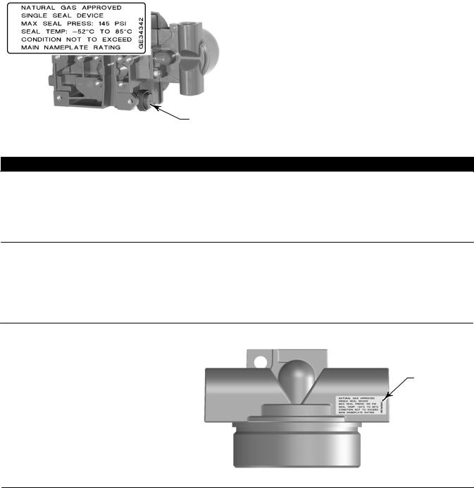
Note
The Natural Gas Certified, Single Seal device option simplifies conduit sealing requirements. Natural Gas Certified, Single Seal instruments can be identified by the natural gas approval label shown in figure 18. Read and follow all local, regional, and federal wiring requirements for natural gas installations. Contact your Emerson Process Management sales office for information on obtaining a Natural Gas Certified, Single Seal DVC6200 digital valve controller.
Figure 18. Label for Natural Gas Certified Terminal Box
LABEL LOCATED
ON TOP OF
TERMINAL BOX
X0748
4.Connect the pneumatic supply line to the 1/4 NPT IN connection on the filter regulator.
5.Proceed to Step 3—Connect the Electrical Wires on page 19.
17
DVC6200 Digital Valve Controllers |
Quick Start Guide |
January 2014 |
D103556X012 |
|
|
18

Quick Start Guide |
DVC6200 Digital Valve Controllers |
|
|
D103556X012 |
|
January 2014 |
|
|
|
|
|
|
|
|
|
|
|
SIS |
|
Step 3—Connect the Electrical Wires

 WARNING
Select wiring and/or cable glands that are rated for the environment of use (such as hazardous area, ingress protection and temperature). Failure to use properly rated wiring and/or cable glands can result in personal injury or property damage from fire or explosion.
Wiring connections must be in accordance with local, regional, and national codes for any given hazardous area approval. Failure to follow the local, regional, and national codes could result in personal injury or property damage from fire or explosion.
To avoid personal injury resulting from electrical shock, do not exceed maximum input voltage specified on the product nameplate. If the input voltage specified differs, do not exceed the lowest specified maximum input voltage.
Personal injury or property damage caused by fire or explosion may occur if this connection is attempted in a potentially explosive atmosphere or in an area that has been classified as hazardous. Confirm that area classification and atmosphere conditions permit the safe removal of the terminal box cover before proceeding.
The valve may move in an unexpected direction when power is applied to the digital valve controller. To avoid personal injury and property damage caused by moving parts, keep hands, tools, and other objects away from the valve/actuator assembly when applying power to the instrument.
For FOUNDATION fieldbus™ or PROFIBUS PA devices proceed to page 20
For HARTr devices proceed to page 22
19
DVC6200 Digital Valve Controllers |
Quick Start Guide |
January 2014 |
D103556X012 |
|
|
FOUNDATION fieldbus or PROFIBUS PA Devices
Refer to the DVC6200f instruction manual (D103412X012) or the DVC6200p instruction manual (D103563X012), available at www.FIELDVUE.com or from your local Emerson Process Management sales office for additional information.
The digital valve controller is normally powered over the bus from a power supply. Refer to the FOUNDATION fieldbus or PROFIBUS site planning guide, available from your Emerson Process Management sales office, for proper wire types, termination, length, grounding practices, etc.
Note
To avoid the valve going to an unknown position when power is applied, the unit digital valve controller is shipped from the factory with the transducer block mode Out of Service.
Wire the digital valve controller as follows, refer to figure 19.
1.Remove the wiring terminal box cap.
2.Bring the field wiring into the terminal box. When applicable, install conduit using local and national electrical codes which apply to the application.
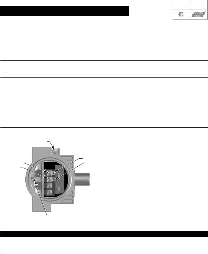
3.The instrument is not polarity sensitive. Connect one wire from the controller output to one of the LOOP screw terminals in the terminal box shown in figure 19. Connect the other wire from the controller output to the other LOOP screw terminal in the terminal box.
Figure 19. Loop Connections Terminal Box
EARTH
GROUND
TALK +
LOOP + |
TALK - |
LOOP -
X0438 |
|
SAFETY |
|
|
GROUND |
|
|
|

 WARNING
Personal injury or property damage can result from the discharge of static electricity. Connect a 14 AWG (2.08 mm2) ground strap between the digital valve controller and earth ground when flammable or hazardous gases are present. Refer to national and local codes and standards for grounding requirements.
20
Quick Start Guide |
DVC6200 Digital Valve Controllers |
D103556X012 |
January 2014 |
|
|
4.Make connections to the ground terminal(s) following national and local codes and plant standards. As shown in figure 19, two ground terminals are available for connecting a safety ground, earth ground, or drain wire. The safety ground terminal is electrically identical to the earth ground.
5.Replace and hand tighten the cover on the terminal box.
6.Write the valve tag number on the top and bottom of the paper commissioning tag, as shown in figure 20.
Figure 20. Paper Commissioning Tag
WRITE THE VALVE
TAG NUMBER HERE
18B9406 G
7.Remove the lower half of the paper commissioning tag and deliver it to the control system configurator. With the piece of paper, the control system configurator will be able to easily change the Device ID placeholder to the actual valve tag number.
Note
Alternatively, the valve tag number can be entered at the factory when specified at the time of order entry. When the valve tag number is electronically stored on the DVC6200, the control system will display the valve tag number instead of the Device ID. As a result, step 6 and 7 will not be required.
8.For Remote Mount applications, proceed to page 26. Otherwise proceed to Step 4—Configure the Digital Valve Controller on page 29.
21
 Loading...