


Instruction Manual |
644 and 645 Pump Governors |
D100302X012 |
February 2014 |
|
|
Fisherr 644 and 645 Differential Pressure Pump
Governors
Contents |
|
|
|
Figure 1. Fisher 644 Actuator Mounted on a Typical |
|
Introduction |
1 |
easy-e™ Valve |
|
||
Scope of Manual . . . . . . . . . . . . . . . . . . . . . . . . . . . . . |
1 |
|
Description . . . . . . . . . . . . . . . . . . . . . . . . . . . . . . . . . |
1 |
|
Specifications . . . . . . . . . . . . . . . . . . . . . . . . . . . . . . . |
2 |
|
Educational Services . . . . . . . . . . . . . . . . . . . . . . . . . |
3 |
|
Installation . . . . . . . . . . . . . . . . . . . . . . . . . . . . . . . . . . |
3 |
|
Direct-Acting Actuators . . . . . . . . . . . . . . . . . . . . . . . |
4 |
|
Reverse-Acting Actuators . . . . . . . . . . . . . . . . . . . . . |
5 |
|
Overpressure . . . . . . . . . . . . . . . . . . . . . . . . . . . . . . . . . |
6 |
|
Startup . . . . . . . . . . . . . . . . . . . . . . . . . . . . . . . . . . . . . . |
6 |
|
Adjustment . . . . . . . . . . . . . . . . . . . . . . . . . . . . . . . . . |
6 |
|
Principle of Operation . . . . . . . . . . . . . . . . . . . . . . . . . |
7 |
|
Maintenance . . . . . . . . . . . . . . . . . . . . . . . . . . . . . . . . . |
7 |
|
Disassembly . . . . . . . . . . . . . . . . . . . . . . . . . . . . . . . . |
8 |
|
Reassembly . . . . . . . . . . . . . . . . . . . . . . . . . . . . . . . . . |
8 |
|
Parts Ordering . . . . . . . . . . . . . . . . . . . . . . . . . . . . . . . |
10 |
|
Parts List . . . . . . . . . . . . . . . . . . . . . . . . . . . . . . . . . . . |
10 |
|
W2265-1
Introduction
Scope of Manual
This instruction manual provides information on installation, adjustment, maintenance, and parts ordering for the Fisher 644 and 645 differential pressure pump governors. Refer to separate instruction manuals for information about the valve and other accessories used with these governors.
Do not install, operate, or maintain 644 or 645 governors without being fully trained and qualified in valve, actuator, and accessory installation, operation, and maintenance. To avoid personal injury or property damage, it is important to carefully read, understand, and follow all the contents of this manual, including all safety cautions and warnings. If you have any questions about these instructions, contact your Emerson Process Management sales office before proceeding.
Description
644 and 645 actuators are used in combination with any of several sliding-stem valves to automatically control steam-driven boiler feedwater pumps (reciprocating or turbine). The 644 or 645 actuator (see figures 1 and 2), when used in combination with one of several push-down-to-close sliding-stem valves, forms a pump governor.
644 and 645 actuators may also be combined with push-down-to-open valves to be used as relief governors. Relief governors are used to divert excess pump discharge back to the suction side of the pump.
www.Fisher.com

644 and 645 Pump Governors |
Instruction Manual |
|
February 2014 |
D100302X012 |
|
|
|
|
Table 1. Specifications |
|
|
|
|
|
Actuator Sizes |
Maximum nP Across Diaphragm |
|
See table 2 |
||
13.8 bar (200 psi) |
||
|
||
Actuator Travel |
Effective Diaphragm Area |
|
Chloroprene Diaphragm: 11 mm (0.4375 inch) |
644: |
|
maximum |
Size 1: 146 cm2 (8.9 inch2) |
|
Stainless Steel Diaphragm: 3 mm (0.125 inch) |
Size 2: 243 cm2 (14.8 inch2) |
|
maximum |
Size 3: 364 cm2 (22.2 inch2) |
|
|
645: 338 cm2 (20.6 inch2) |
|
Operating Principle |
Material Temperature Capabilities |
|
J Direct-acting with push-down-to-close valve |
||
644: |
||
J Reverse-acting with push-down-to-open valve |
||
Chloroprene Diaphragm:-40 to 82_C |
||
|
||
|
(-40 to 180_F) |
|
Differential Pressure Ranges |
Stainless Steel Diaphragm: |
|
See table 2 |
Cast-iron casing: -40 to 232_C (-40 to 450_F); Steel |
|
casing: -40 to +399_C (-40 to 750_F) |
||
|
||
Maximum Casing Pressure |
645: -37 to 82_C (-35_ to 180_F) |
|
|
||
644 Actuator: |
Casing Pressure Connections |
|
Cast-Iron Casing: 20.7 bar (300 psig) |
1/4 NPT internal |
|
Steel Casing: 41.4 bar (600 psig) |
||
|
||
645 Actuator: |
Spring Ranges and Sensitivity |
|
Cast-Iron Casing: 34.5 bar (500 psig) |
||
See table 2 |
||
Steel Casing: 69.0 bar (1000 psig) |
||
|
|
Specifications
Specifications for the 644 and 645 pump governors are shown in table 1. Information for a specific pump governor is also found on the nameplate of that pump governor.
Table 2. Spring Information
ACTUATOR |
DIFFERENTIAL PRESSURE RANGE |
SPRING RATE |
SENSITIVITY |
SPRING PART NUMBER |
||||||
Bar |
Psi |
N/mm |
Lbf/in |
mm/N |
In/Psi |
|||||
|
|
|
|
|||||||
|
|
Size 3 |
0.3-1.2 |
5-18 |
56 |
314 |
26.1 |
0.0707 |
1F945527032 |
|
|
|
Casing |
1.2-1.9 |
18-27 |
107 |
609 |
13.5 |
0.0365 |
1F945627032 |
|
|
|
|
|
|
|
|
|
|
|
|
644 |
|
Size 2 |
1.9-2.8 |
27-40 |
107 |
609 |
9.0 |
0.0244 |
1F945627032 |
|
|
Casing |
2.8-3.8 |
40-55 |
165 |
940 |
6.2 |
0.0168 |
1F945727042 |
||
|
|
|||||||||
|
|
|
|
|
|
|
|
|
|
|
|
|
Size 1 |
3.8-4.7 |
55-68 |
107 |
609 |
5.4 |
0.0146 |
1F945627032 |
|
|
|
Casing |
4.7-6.9 |
68-100 |
165 |
940 |
3.7 |
0.0101 |
1F945727042 |
|
|
|
|
|
|
|
|
|
|
|
|
|
|
|
1.0-1.7 |
14-24 |
43 |
246 |
21.0 |
0.057 |
1F714427112 |
|
|
|
|
1.7-2.4 |
24-35 |
64 |
368 |
14.0 |
0.038 |
1F176727032 |
|
|
|
|
2.4-3.2 |
35-47 |
86 |
490 |
10.5 |
0.0286 |
1F176827092 |
|
|
|
|
3.2-4.1 |
47-59 |
107 |
612 |
11.0 |
0.0299 |
1F176927092 |
|
|
645 |
4.1-4.3 |
59-62 |
129 |
735 |
7.1 |
0.0191 |
1E792327092 |
||
|
|
|
|
|
|
|
|
|||
|
4.3-5.9 |
62-85 |
145 |
830 |
6.2 |
0.0169 |
1F714327092 |
|||
|
|
|
||||||||
|
|
|
5.9-6.8 |
85-99 |
221 |
1260 |
4.1 |
0.0111 |
1E795327082 |
|
|
|
|
6.8-8.2 |
99-119 |
257 |
1470 |
3.5 |
0.0095 |
1E792427082 |
|
|
|
|
8.2-9.7 |
119-140 |
310 |
1770 |
2.9 |
0.0079 |
1E795427082 |
|
|
|
|
9.7-10.7 |
140-155 |
368 |
2100 |
2.5 |
0.0067 |
1E793327082 |
|
2

Instruction Manual |
644 and 645 Pump Governors |
D100302X012 |
February 2014 |
|
|
Educational Services
For information on available courses for Fisher 644 and 645 pump governors, as well as a variety of other products, contact:
Emerson Process Management Educational Services - Registration P.O. Box 190
Marshalltown, IA 50158-2823
Phone: 800-338-8158 or 641-754-3771 FAX: 641-754-3431
e-mail: education@emerson.com
Figure 2. Typical Pump Governor Sectionals
W2263-1 |
W2264-1 |
|
|
644 ED |
645 ED |
|
|

 WARNING
These governors must be installed, operated, and maintained in accordance with Fisher instructions and all applicable federal, state, and local codes, laws, rules and regulations.
If a leak develops in the system or if any of the equipment is damaged, service is required. Failure to investigate problems immediately may cause a hazardous condition.
Call a serviceman in case of trouble. Only a qualified person must install or service the actuator.
Installation

 WARNING
Always wear protective gloves, clothing, and eyewear when performing any maintenance operations to avoid personal injury.
3
644 and 645 Pump Governors |
Instruction Manual |
February 2014 |
D100302X012 |
|
|
To avoid personal injury or property damage caused by bursting of pressure-retaining parts, be certain the service
conditions do not exceed the casing pressure limit (maximum nP across the diaphragm) of 13.8 bar (200 psi). Use pressure-limiting or pressure-relieving devices to prevent service conditions from exceeding this limit.
Check with your process or safety engineer for any other hazards that may be present from exposure to process media.
If installing into an existing application, also refer to the WARNING at the beginning of the Maintenance section in this instruction manual.
Normal operating temperature range for the 644 actuator is from -40 to 82_C (-40 to 180_F). For the 645 actuator, the range is from -37 to 82_C (-35 to 180_F).
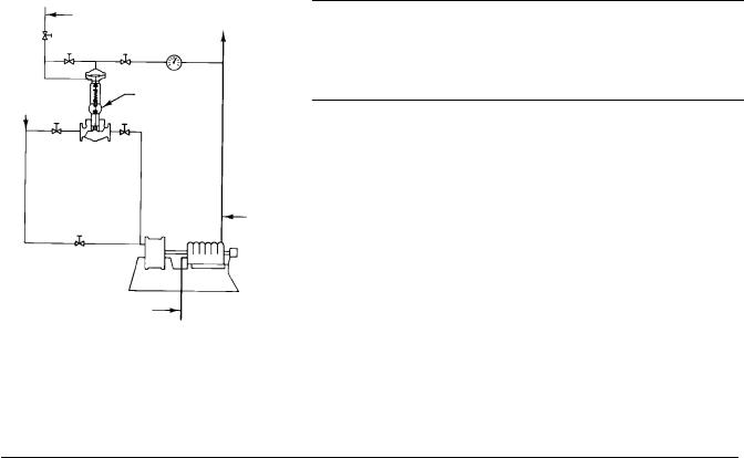
Figure 3. Typical Installation for a Direct-Acting Governor
CONNECT TO BOILER PRESSURE
|
A F |
B |
STEAM |
|
645-ED PUMP |
SUPPLY |
E |
C ACTUATOR |
D |
PUMP |
DISCHARGE |
14A2729-A
A1762
SUCTION
Direct-Acting Actuators
Proceed as follows to install 644 and 645 actuators that are used with push-down-to-close valves (644-ED, 645-ED). Refer to figure 3.
1.Place the governor in the steam line between a hand operated throttle valve (C) and the steam inlet to the pump. The governor may be installed in any position, as long as the flow is in the direction of the arrow cast on the valve body. However, when used for steam service, the unit should be installed so condensate will drain back into the diaphragm casing and maintain a water seal on the diaphragm. Failure to do so may impact performance.
2.Install a hand-operated throttle valve (E) between the governor and the steam supply line.
3.Run a 1/4-inch control line from the upper diaphragm casing to the side or top of the pump discharge line. Keep the control line away from any nipple, swage, or elbow.
4.Install a lock-shield needle valve (B) and a pressure gauge in this control line.
5.Run a second 1/4-inch control line from the lower diaphragm casing to the boiler steam pressure line. Install a needle valve (A) in this line. Slope the line toward the actuator in order to form a water seal on the diaphragm.
6.Connect the two control lines with an equalizing line in which a needle valve (F) has been installed.
4
 Loading...