


Fisher 3610J
Instruction Manual
D200149X012
3610J and 3620J Positioners
January 2015
Fisherr 3610J and 3620J Positioners and 3622
Electro‐Pneumatic Converter
Contents
Introduction 2.................................
Scope of Manual 2.............................
Description 2.................................
Type Number Description 6.....................
Specifications 6...............................
Educational Services 6.........................
Installation 6..................................
Hazardous Area Classifications and
Special Instructions for “Safe Use” and
Installation in Hazardous Locations
for 3622 converter 7........................
CSA 8....................................
FM 8.....................................
ATEX 9...................................
IECEx 10..................................
Mounting 3610J, 3610JP,
3620J, and 3620JP Positioners 11..............
Changing Cams—Actuator
Styles A, B, C, and D 13.......................
Mounting 3611JP and 3621JP Positioners
on 585 and 585R Actuators 14................
Mounting 3611JP and 3621JP Positioners
on 585C and 585CR Actuators 16..............
Installing the 3622
Electro‐Pneumatic Converter 18...............
Changing Positioner Types 18...................
Pressure Connections 18.......................
Supply Connection 19......................
Output Connections 19.....................
Instrument Connection 20..................
Diagnostic Connections 21..................
Vent Connection 22...........................
Electrical Connections
for 3620J Positioners 23......................
Calibration 23..................................
Minor Loop Gain Adjustment 24.................
Crossover Adjustment 25.......................
3610J or 3620J Positioner,
Spring and Diaphragm Actuators 25........
3610JP, 3611JP, 3620JP, or 3621JP
Positioner, Piston Actuators 26............
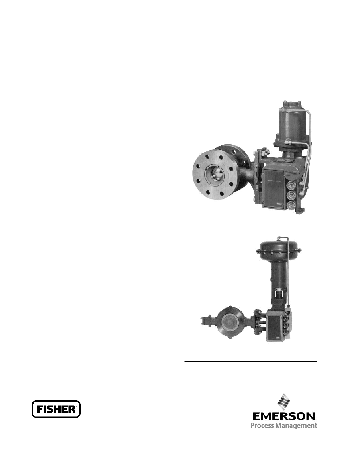
Figure 1. Typical Positioners
W4920-1 / IL
3620JP POSITIONER WITH FISHER
1061 ACTUATOR AND V500 VALVE
W3949 / IL
3610J POSITIONER AND BYPASS VALVE WITH FISHER
1052 ACTUATOR AND ECCENTRIC DISC ROTARY VALVE
www.Fisher.com

3610J and 3620J Positioners
January 2015
Instruction Manual
D200149X012
Zero and Span Adjustments 27..................
Changing Positioner Action 28..................
Changing to Direct Action 29................
Changing to Reverse Action 29...............
Split Range Operation 30.......................
Characterized Cams for 3610J, 3610JP,
3620J, and 3620JP Positioners 31..............
Principle of Operation 32........................
Maintenance 35................................
Positioner Disassembly 37......................
Removing the Positioner from the Actuator 37.
Disassembling the Bypass Valve 38...........
Disassembling the Gauge Block 38...........
Disassembling the 3622
Electro‐Pneumatic Converter 39...........
Disassembling the Feedback
Lever Assembly 39.......................
Disassembling the Reversing
Plate and Gasket 40......................
Disassembling the Relay 40.................
Disassembling the Summing Beam
Assembly 40............................
Introduction
Disassembling the Nozzle Assembly 41........
Disassembling the Input Module 42...........
Positioner Reassembly 42.......................
Assembling the Input Module 42.............
Assembling the Nozzle Assembly 43..........
Assembling the Summing Beam Assembly 43..
Assembling the Relay 44....................
Assembling the Reversing Plate
and Gasket 45..........................
Assembling the Gauge Block 45..............
Assembling the 3622
Electro‐Pneumatic Converter 45...........
Assembling the Feedback Lever Assembly 46...
Assembling the Bypass Valve Assembly 46.....
Changing Positioner Types 47...................
Parts Ordering 49...............................
Parts Kits 49..................................
Parts List 49..................................
Positioner Common Parts 49................
3622 Electro‐Pneumatic Converter 52.........
Diagnostic Connections 53..................
Loop Schematics 62.............................
Scope of Manual
This instruction manual includes installation, operation, calibration, maintenance, and parts ordering information for
Fisher 3610J and 3620J positioners. (i.e. 3610J, 3610JP, 3611JP, 3620J, 3620JP, and 3621JP). This manual also provides
field installation information for the Fisher 3622 electro‐pneumatic converter. Refer to separate instruction manuals
for information on the actuator and control valve. Contact your Emerson Process Management sales office if assistance
is needed in obtaining actuator or control valve instruction manuals.
Do not install, operate or maintain a 3610J or 3620J positioner without being fully trained and qualified in valve,
actuator and accessory installation, operation and maintenance. To avoid personal injury or property damage it is
important to carefully read, understand, and follow all of the contents of this manual, including all safety cautions and
warnings. If you have any questions about these instructions, contact your Emerson Process Management sales office
before proceeding.
Description
3610J or 3610JP pneumatic positioners and 3620J or 3620JP electro‐pneumatic positioners are used with diaphragm
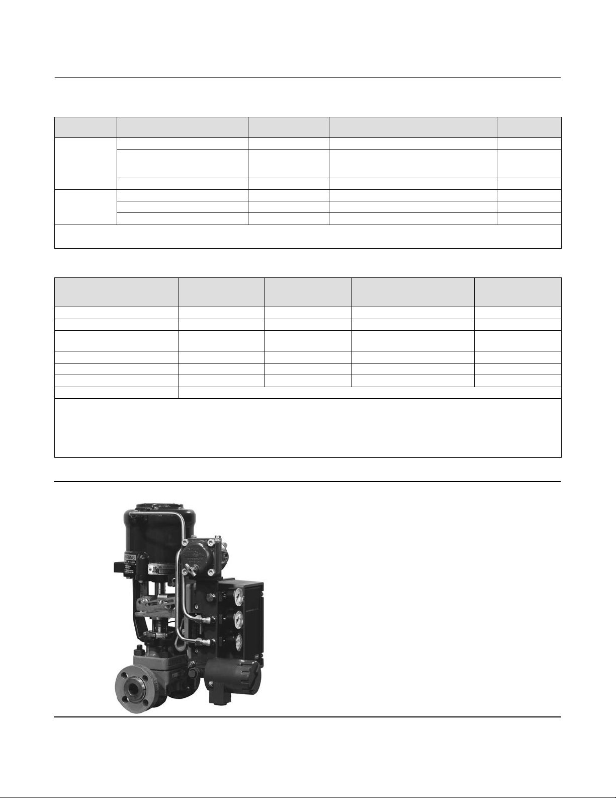
rotary actuators and piston rotary actuators as shown in figure 1. 3611JP and 3621JP positioners are used with Fisher
585, 585R, 585C, or 585CR sliding stem actuators as shown in figure 2.
The positioner mounts integrally to the actuator housing and provides a valve ball, disk, or plug position for a specific
input signal. The positioner accepts either a pneumatic or milliampere input signal. Refer to the Type Number
Description for a detailed explanation of type numbers.
2

Instruction Manual
D200149X012
Table 1. Specifications
3610J and 3620J Positioners
January 2015
Unless otherwise specified, the specifications listed
are for all positioner type numbers
Available Configurations
Refer to the type number description
Input Signal
3610J, 3610JP, and 3611JP: Standard: J 0.2 to 1.0
bar (3 to 15 psig), J 0.4 to 2.0 bar (6 to 30 psig), or
J split range, see table 12
Adjustable: Zero is adjustable from 0.07 to 1.5 bar
(1 to 22 psig) for standard valve rotations or valve
travels. Span is adjustable from 0.2 to 2.0 bar (3.2 to
28.8 psi) for standard valve rotations or valve travels.
Adjustment locations are shown in figure 13.
3620J, 3620JP, and 3621JP: 4 to 20 mA DC constant
current with 30 VDC maximum compliance voltage.
Minimum terminal voltage is 2.4 VDC at 20 mA. Split
range is also available, see table 12.
Equivalent Circuit
3620J, 3620JP, and 3621JP: 120 ohms shunted by
three 5.6 V zener diodes
Output Signal
Pneumatic pressure as required by the actuator up to
full supply pressure
(1)
Action
: Field‐reversible between J direct and
J reverse within the pneumatic positioner
Typical Performance for 3610J, 3610JP, 3620J, and
3620JP Positioners with 1051, 1052, and 1061
Actuators
Independent Linearity
Direct‐Acting 3610J and 3620J: ±1.5% of output span
Reverse‐Acting 3610J and 3620J: ±0.75% of output span
Direct‐Acting 3610JP and 3620JP: ±1.25% of output
span
Reverse‐Acting 3610JP and 3620JP: ±0.5% of output
span
Hysteresis
3610J: 1.0% of output span
3620J: 0.75% of output span
3610JP: 0.5% of output span
3620JP: 0.6% of output span
Deadband: 0.1% of input span
Refer to table 3 for typical performance for 3611JP
and 3621JP positioners
- continued -
Electromagnetic Compatibility for 3622
electro‐pneumatic converter
Meets EN 61326‐1 (First Edition)
Immunity—Industrial locations per Table 2 of the
EN 61326‐1 standard. Performance is shown
in table 2 below.
Emissions—Class A
ISM equipment rating: Group 1, Class A
The electromagnetic compatibility specifications also
apply to 3620J, 3620JP, and 3621JP
electro‐pneumatic positioners.
Maximum Supply Air Demand
3610J and 3620J:
1.4 bar (20 Psig) Supply: 13 normal m
2.4 bar (35 Psig) Supply: 17 normal m
3610JP, 3620JP, 3611JP, and 3621JP:
5.2 Bar (75 Psig) Supply: 37 normal m
(1380 scfh)
6.9 Bar (100 Psig) Supply: 46 normal m
(2)
3
/hour (490 scfh)
3
/hour (640 scfh)
3
/hour
3
/hour
(1700 scfh)
Operating Influences for 3610J, 3610JP, 3620J, and
3620JP
Supply Pressure Sensitivity: A 10% change in supply
pressure changes the valve shaft position less than
the following percentages of valve rotation:
3610J and 3620J: 1.0% at 1.4 bar (20 psig) supply
pressure
3610JP and 3620JP: 1.5% at 4.1 bar (60 psig) supply
pressure
Supply Pressure
(3)
Minimum Recommended: 0.3 bar (5 psig) above
actuator requirement [1.4 bar (20 psig) for a 0.2 to
1.0 bar (3 to 15 psig) nominal actuator signal; 2.4 bar
(35 psig) for a 0.4 to 2.0 bar (6 to 30 psig) nominal
actuator signal]
Maximum: 10.3 bar (150 psig) or maximum pressure
rating of the actuator, whichever is lower
Supply Medium: Air or natural gas
(4)
3620J, 3620JP, 3621JP positioners are not approved
for use with natural gas as the supply medium.
3
3610J and 3620J Positioners
January 2015
Table 1. Specifications (Continued)
Instruction Manual
D200149X012
Steady‐State Air Consumption
(2)
3610J: 0.40 normal m3/hour (15 scfh) at 1.4 bar
(20 psig) supply pressure
3610JP: 0.64 normal m
3
/hour (24 scfh) at 6.9 bar
(100 psig) supply pressure
3620J: 0.49 normal m
(20 psig) supply pressure
3620JP: 0.93 normal m
3
/hour (18.2 scfh) at 1.4 bar
3
/hour (35.0 scfh) at 6.9 bar
(100 psig) supply pressure
Operative Temperature Limits
(3)
-40 to 82_C (-40 to 180_F)
Hazardous Area Classification for 3610J, 3610JP,
and 3611JP
Complies with the requirements of ATEX Group II
Category 2 Gas and Dust
Electrical Classification for 3622
Hazardous Area:
CSA—Intrinsically Safe, Explosion proof, Type n,
Dust‐Ignition proof, DIV 2
FM—Intrinsically Safe, Explosion proof, Type n,
Dust‐Ignition proof, Non‐incendive
ATEX—Intrinsically Safe, Flameproof, Type n
IECEx—Intrinsically Safe, Flameproof, Type n
(Gas Atmospheres only)
office for classification/certification specific
information
Note: These classifications also apply to 3620J
positioners
Housing Classification for 3622
CSA—Type 3 Encl.
FM—NEMA 3, IP54
ATEX—IP64
IECEx—IP54
Mount instrument with vent on side or bottom if
weatherproofing is a concern
Note: These classifications also apply to 3620J
positioners
Pressure Connections
1/4 NPT internal
Electrical Connection for 3620J, 3620JP, and 3621JP
1/2‐14 NPT conduit connection
Rotary Valve Rotation
60, 75, or 90 degrees
Sliding Stem Valve Travel
102 mm (4 inches), adjustable to lesser travel with
standard input signals
Refer to Hazardous Area Classifications and Special
Instructions for “Safe Use” and Installation in
Hazardous Locations, starting on page 7, for
additional information.
Note: These classifications also apply to 3620J
positioners
Other Classifications/Certifications for 3622
GOST‐R—Russian GOST‐R
INMETRO— National Institute of Metrology, Quality
and Technology (Brazil)
KGS— Korea Gas Safety Corporation (South Korea)
RTN—Russian Rostekhnadzor
Contact your Emerson Process Management sales
NOTE: Specialized instrument terms are defined in ANSI/ISA Standard 51.1 - Process Instrument Terminology.
1. For direct action, an increasing input signal extends actuator rod. For reverse action, an increasing input signal retracts actuator rod.
2. Normal m
3. The pressure and temperature limits in this document, and any applicable code or standard should not be exceeded.
4. Natural gas should contain no more than 20 ppm of H
4
3
/hr—Normal cubic meters per hour (0_C and 1.01325 bar, absolute). Scfh—Standard cubic feet per hour (60_F and 14.7 psia).
S.
2
Approximate Weight
3610J positioners: 2.5 kg (5.6 pounds)
3620J positioners: 3.6 kg (8.0 pounds)
Declaration of SEP
Fisher Controls International LLC declares this
product to be in compliance with Article 3 paragraph
3 of the Pressure Equipment Directive (PED) 97 / 23 /
EC. It was designed and manufactured in accordance
with Sound Engineering Practice (SEP) and cannot
bear the CE marking related to PED compliance.
However, the product may bear the CE marking to
indicate compliance with other applicable European
Community Directives.
Instruction Manual
D200149X012
3610J and 3620J Positioners
January 2015
Table 2. Fisher 3622 Electro‐Pneumatic Converter
(1)
EMC Summary Results—Immunity
Port Phenomenon Basic Standard Test Level
Electrostatic Discharge (ESD) IEC 61000‐4‐2 4 kV contact; 8 kV air A
Enclosure
Radiated EM field IEC 61000‐4‐3
80 to 1000 MHz @ 10V/m with 1 kHz AM at 80%
1400 to 2000 MHz @ 3V/m with 1 kHz AM at 80%
2000 to 2700 MHz @ 1V/m with 1 kHz AM at 80%
Rated power frequency magnetic field IEC 61000‐4‐8 60 A/m at 50 Hz A
Burst IEC 61000‐4‐4 1 kV A
I/O signal/control
Surge IEC 61000‐4‐5 1 kV (line to ground only, each) B
Conducted RF IEC 61000‐4‐6 150 kHz to 80 MHz at 3 Vrms A
Specification limit = ±1% of span
1. The information contained in the table also applies to 3620J, 3620JP, and 3621JP electro‐pneumatic positioners.
2. A=No degradation during testing. B = Temporary degradation during testing, but is self‐recovering.
Table 3. Typical Performance Specifications
Characteristic
Deadband
Step Response
(1)
(1,4,5)
Steady‐State Air Consumption
Hysteresis
Terminal‐Based Linearity
Frequency Response
(3)
(8)
(1)
(-6 dB) 2 Hz 2 Hz 0.2 Hz 2 Hz
(6,7)
Size 25 Actuator
0.1% of input span 0.1% of input span 0.1% of input span 0.1% of input span
0.3 seconds 0.3 seconds 2 seconds 0.3 seconds
0.01 normal m3/min
(0.4 scfm)
0.5% of output span 0.5% of output span 0.5% of output span 0.5% of output span
1% of output span 1% of output span 1% of output span 1% of output span
(1)
for Fisher 3611JP and 3621JP Positioners with 585, 585R, 585C, and 585CR Actuators
585C and 585CR
(2)
Size 50 Actuator
0.01 normal m3/min
(0.4 scfm)
585C and 585CR
(2)
Size 100 Actuator Standard
0.01 normal m3/min
(0.4 scfm)
585 and 585R
Supply Pressure Sensitivity 10% change in supply pressure changes the actuator stem position less than 0.1%
1. Performance tests are based on 6.9 bar (100 psig) supply pressure and lightest actuator springs. Performance will vary with other pressures and springs.
2. Size 25 and 50 actuators tested with appropriate parallel flexure (key 179).
3. Equipped with two 2625 boosters with 1/2 inch supply and exhaust ports.
4. Step response is the time for the actuator to reach 63 percent of expected travel after a 10 percent step change in input signal.
5. 3621JP positioner step response equals 0.4 seconds.
6. At 6.9 bar (100 psig) supply pressure. Normal m
7. 3621JP positioner steady‐state air consumption equals 0.02 normal m
8. 3621JP positioner terminal‐based linearity equals ±2.25%.
3
/min‐cubic meters per minute (0_C and 1.01325 bar). Scfm‐‐standard cubic feet per minute (60_F and 14.7 psia).
3
/min (0.58 scfm).
Performance
Criteria
(1)
A
585 and 585R
Size 100 Actuator with
Boosters
(3)
0.01 normal m3/min
(0.4 scfm)
Figure 2. Fisher 3621JP Positioner with 585C Actuator
W6594 / IL
5

3610J and 3620J Positioners
January 2015
Instruction Manual
D200149X012
Type Number Description
The following descriptions provide specific information on the different positioner constructions. If the type number is
not known, refer to the nameplate on the positioner. For the nameplate location, refer to key 157, figure 25.
3610J: A single‐acting pneumatic rotary valve positioner for use with Fisher 1051, 1052, and 2052 actuators.
3610JP: A double‐acting pneumatic rotary valve positioner for use with Fisher 1061 and 1069 actuators.
3611JP: A double‐acting pneumatic sliding stem valve positioner for use with 585, 585R, 585C, and 585CR actuators.
3620J: A single‐acting electro‐pneumatic rotary valve positioner for use with 1051, 1052, and 2052 actuators.
3620JP: A double‐acting electro‐pneumatic rotary valve positioner for use with 1061 and 1069 actuators.
3621JP: A double‐acting electro‐pneumatic sliding stem valve positioner for use with 585, 585R, 585C, and 585CR
actuators.
3622: An electro‐pneumatic converter used for conversion of a 4 to 20 milliampere DC input signal to a 0.2 to 1.0 bar
(3 to 15 psig) input signal for the pneumatic positioner. Use this unit in combination with a 3610J, 3610JP, or 3611JP
positioner to make a 3620J, 3620JP or a 3621JP positioner.
Specifications
WARNING
This product is intended for a specific range of pressure, temperatures and other application specifications. Applying
different pressure, temperature and other service conditions could result in malfunction of the product, which could cause
property damage or personal injury.
Specifications for the valve positioners are shown in table 1. Performance specifications for 3611JP and 3621JP
positioners are shown in table 3.
Educational Services
For information on available courses for 3610J and 3620J positioners, as well as a variety of other products, contact:
Emerson Process Management
Educational Services, Registration
Phone: +1-641-754-3771 or +1-800-338-8158
e‐mail: education@emerson.com
http://www.emersonprocess.com/education
Installation
Normally, a positioner is shipped with the actuator. If so, the factory mounts and calibrates the positioner and
connects the positioner to actuator tubing. If the positioner is ordered separately from the actuator, perform the
appropriate mounting procedure, and follow the Calibration procedures in this instruction manual. Refer to the
appropriate instruction manuals for actuator and valve mounting procedures.
6

Instruction Manual
D200149X012
3610J and 3620J Positioners
January 2015
WARNING
Avoid personal injury from sudden release of process pressure. Before mounting the positioner:
D Always wear protective clothing gloves, and eyewear when performing any installation operations to avoid personal
injury.
D When installing 3620J positioners in a hazardous area, turn off control signals until installation is complete. Be sure all
safety barriers, connections, and the converter housing cap and O‐ring are properly installed before applying a control
signal to the unit.
D If installing into an existing application, also refer to the WARNING at the beginning of the Maintenance section.
D Check with your process or safety engineer for any additional measures that must be taken to protect against process
media.
WARNING
Personal injury or property damage may result from fire or explosion if natural gas is used as the supply medium and
appropriate preventive measures are not taken. Preventive measures may include, but are not limited to, one or more of
the following: Remote venting of the unit, re‐evaluating the hazardous area classification, ensuring adequate ventilation,
and the removal of any ignition sources.
3620J, 3620JP, 3621JP positioners and the 3622 electro‐pneumatic converter do not meet third party approvals for use with
natural gas as the supply medium. Use of natural gas as the supply medium can result in personal injury or property
damage from fire or explosion.
Hazardous Area Classifications and Special Instructions for “Safe Use” and
Installation in Hazardous Locations for 3622 Converter
Certain nameplates may carry more than one approval, and each approval may have unique installation/wiring
requirements and/or conditions of “safe use”. These special instructions for “safe use” are in addition to, and may
override, the standard installation procedures. Special instructions are listed by approval.
Note
This information supplements the nameplate markings affixed to the product.
Always refer to the nameplate itself to identify the appropriate certification. Contact your Emerson Process Management sales
office for approval/certification information not listed here.
WARNING
Failure to follow these conditions of “safe use” could result in personal injury or property damage from fire or explosion,
and area re‐classification.
7

3610J and 3620J Positioners
January 2015
Instruction Manual
D200149X012
CSA
Intrinsically Safe, Explosion-proof, Type n, Dust‐Ignition proof, DIV 2
No special conditions for safe use.
Refer to table 4 for approval information.
Table 4. Hazardous Area Classifications for Fisher 3622 Converter
Certification Body Certification Obtained Entity Rating Temperature Code
Intrinsically Safe
Ex ia IIC T4/T5/T6 per drawing GE28591 (see figure 31)
Ex ia Intrinsically Safety
Class I, II Division 1 GP A,B,C,D,E,F,G
T4/T5/T6 per drawing GE28591 (see figure 31)
Explosion-proof
CSA
1. These hazardous area classification also apply to 3620J positioners.
Ex d IIC T5
Class I, Division I, GP A,B,C,D T5
Type n
Ex nA IIC T6
Class I, Division 2, GP A,B,C,D T6
Class II, Division 1, GP E,F,G T5 T5 (Tamb ≤ 82°C)
Class II, Division 2, GP F,G T6 T6 (Tamb ≤ 82°C)
(1)
—CSA (Canada)
Vmax = 30 VDC
Imax = 150 mA
Pi = 1.25 W
Ci = 0 nF
Li = 0 mH
- - - T5 (Tamb ≤ 82°C)
- - - T6 (Tamb ≤ 82°C)
- - -
T4 (Tamb ≤ 82°C)
T5 (Tamb ≤ 62°C)
T6 (Tamb ≤ 47°C
T6 (Tamb ≤ 82°C)
FM
Intrinsically Safe, Explosion-proof, Type n, Dust‐Ignition proof, Non‐incendive
No special conditions for safe use.
Refer to table 5 for approval information.
Table 5. Hazardous Area Classifications for Fisher 3622 Converter
Certification Body Certification Obtained Entity Rating Temperature Code
Intrinsically Safe
Class 1 Zone 0 AEx ia IIC T4/T5/T6 per drawing GE28590 (see figure 32)
Class I, II, III Division 1 GP A,B,C,D,E,F,G T4/T5/T6
per drawing GE28590 (see figure 32)
Explosion-proof
FM
1. These hazardous area classification also apply to 3620J positioners.
Class 1 Zone 1 AEx d IIC T5
Class I, Division I, GP A,B,C,D T5
Type n
CL 1 Zone 2 AEx nA IIC T5
Class I, Division 2, GP A,B,C,D T5
Class II, Division 1, GP E,F,G T5
Class II, Division 2, GP F,G T5
(1)
—FM (United States)
Vmax = 30 VDC
Imax = 150 mA
Pi = 1.25 W
Ci = 0 nF
Li = 0 mH
T4 (Tamb ≤ 82°C)
T5 (Tamb ≤ 62°C)
T6 (Tamb ≤ 47°C)
- - - T5 (Tamb ≤ 82°C)
- - - T5 (Tamb ≤ 82°C)
- - - T5 (Tamb ≤ 82°C)
8

Instruction Manual
D200149X012
3610J and 3620J Positioners
January 2015
ATEX
Standards Used for Certification
EN 60079-0: 2012 EN 60079-31: 2009
EN 60079-1: 2007 EN 61241-0: 2006
EN 60079-11: 2012 EN 61241-1: 2004
EN 60079-15: 2010 EN 61241-11: 2006
Special Conditions of Use
Intrinsically Safe
This equipment is intrinsically safe and can be used in potentially explosive atmospheres.
The electrical parameters of certified equipment which can be connected to the device must not exceed the following
values:
≤ 30 VDC
U
0
I
≤ 150 mA
0
P
≤ 1.25 W
0
Ambient temperature:
T6, at Tamb = 47_C
T5, at Tamb = 62_C
T4, at Tamb = 82_C
Flameproof
The flame path is other than required by EN 60079‐1. Contact the manufacturer for information on the dimensions of
the flameproof joints.
Electrical connections are typically made using either cable or conduit.
D If using a cable connection, the cable entry device shall be certified in type of explosion protection flameproof
enclosure “d”, suitable for the conditions of use and correctly installed.
For ambient temperatures over 70_C, cables and cable glands suitable for at least 90_C shall be used.
D If using a rigid conduit connection, an Ex d certified sealing device such as a conduit seal with setting compound
shall be provided immediately to the entrance of the enclosure.
For ambient temperatures over 70_C, the wiring and setting compound in the conduit seal shall be suitable for at least
90_C.
Type n
No special conditions for safe use.
Refer to table 6 for additional approval information.
9
3610J and 3620J Positioners
January 2015
Instruction Manual
D200149X012
Table 6. Hazardous Area Classifications for Fisher 3622 Converter
Certificate Certification Obtained Entity Rating Temperature Code
II 1 G & D
Intrinsically Safe
Gas
Ex ia IIC T4/T5/T6 Ga
Dust
Ex ia IIIC Da T120 °C (Tamb ≤ 82°C) / T100 °C (Tamb ≤ 62°C)
/ T85 °C (Tamb ≤ 47°C)
II 2 G & D
ATEX
1. These hazardous area classification also apply to 3620J positioners.
Flameproof
Gas
Ex d IIC T5 Gb
Dust
Ex tb IIIC T82 °C Db (Tamb ≤ 79°C)
II 3 G & D
Type n
Gas
Ex nA IIC T6 Gc
Dust
Ex tc IIIC T85 °C Dc (Tamb ≤ 82°C)
(1)
—ATEX
Ui = 30 VDC
Ii = 150 mA
Pi = 1.25 W
Ci = 0 nF
Li = 0 mH
- - -
- - -
T4 (Tamb ≤ 82°C)
T5 (Tamb ≤ 62°C)
T6 (Tamb ≤ 47°C)
T5 (Tamb ≤ 82°C)
T6 (Tamb ≤ 82°C)
IECEx
Conditions of Certification
- - -
- - -
- - -
Intrinsically Safe
WARNING
Substitution of components may impair intrinsic safety.
-40_C ≤ Ta ≤ +82_C; T6 (Ta ≤ +47_C); T5 (Ta ≤ +62_C); T4 (Ta ≤ +82_C)
Entity Parameters: Ui = 30 V, li = 150 mA, Pi = 1.25 W, Ci = 0 nF, Li = 0 mH
Flameproof
WARNING
Disconnect power before opening.
-40_C ≤ Ta ≤ +82_C; T5 (Ta ≤ +82_C)
Type n
WARNING
Disconnect power before opening.
-40_C ≤ Ta ≤ +82_C; T6 (Ta ≤ +82_C)
Refer to table 7 for additional approval information.
10

Instruction Manual
D200149X012
3610J and 3620J Positioners
January 2015
Table 7. Hazardous Area Classifications for Fisher 3622 Converter
Certificate Certification Obtained Entity Rating Temperature Code
Intrinsically Safe
Gas
Ex ia IIC T4/T5/T6 Ga
IECEx
1. These hazardous area classification also apply to 3620J positioners.
Flameproof
Gas
Ex d IIC T5 Gb
Type n
Gas
Ex nA IIC T6 Gc
(1)
—IECEx
Ui = 30 VDC
Ii = 150 mA
Pi = 1.25 W
Ci = 0 nF
Li = 0 mH
- - - T5 (Tamb ≤ 82°C)
- - - T6 (Tamb ≤ 82°C)
T4 (Tamb ≤ 82°C)
T5 (Tamb ≤ 62°C)
T6 (Tamb ≤ 47°C)
Mounting 3610J, 3610JP, 3620J, and 3620JP Positioners
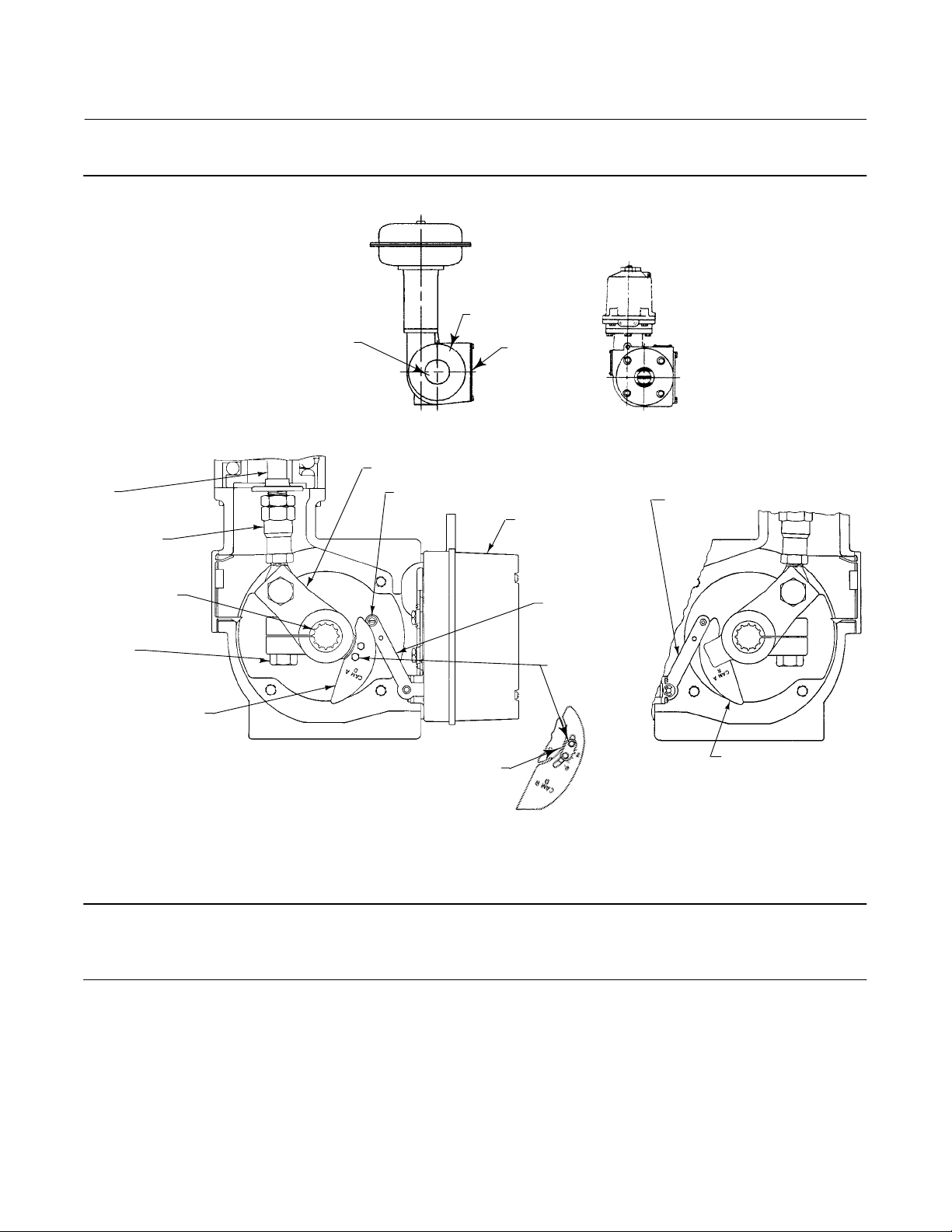
During the following mounting procedures, refer to figure 3 for part locations. Refer to figure 28 for key number
locations unless otherwise indicated.
1. Mark the positions of the travel indicator and actuator cover. Then, remove the actuator travel indicator machine
screws, travel indicator, and actuator cover cap screws.
2. Remove the positioner plate from the actuator housing.
3. For actuator styles A and D, proceed to the note before step 7. For actuator styles B and C, continue with step 4.
4. Disconnect the actuator turnbuckle from the lever arm.
Note
Do not change the position of the rod end bearing on the end of the turnbuckle.
5. Loosen the lever clamping bolt in the lever.
6. Mark the lever/valve shaft orientation, and remove the lever.
11
3610J and 3620J Positioners
January 2015
Figure 3. Typical Mounting Details for Fisher 3610J and 3620J Positioners on Rotary Actuators
ACTUATOR
COVER
TRAVEL INDICATOR
POSITIONER
PLATE
Instruction Manual
D200149X012
ACTUATOR
ROD
TURNBUCKLE
SPLINED END
OF SHAFT
LEVER CLAMPING
BOLT
CAM (KEY 82)
48A7851-C
C0572-2/IL
14A7222-G
STYLE A OR D
ACTUATOR AND POSITIONER WITH ACTUATOR COVER REMOVED
ACTUATOR WITHOUT POSITIONER
LEVER ARM
ROLLER (KEY 39)
POSITIONER COVER
(KEY 41)
CAM ADJUSTMENT INDICATOR
(KEY 84, NOT USED ON CAM A)
58A7810-W
14A7224-D
FEEDBACK LEVER
ASSEMBLY (KEY 117)
CAM MOUNTING
MACHINE
SCREWS (KEY 83)
11B4045-A
FEEDBACK
LEVER
ASSEMBLY
(KEY 117)
CAM
(KEY 82)
STYLE B OR C
Note
Cams A, B, and C have the letter D (direct acting) on one side and the letter R (reverse acting) on the other side. Always install the
cam with the letter D on the same side as the cam mounting screw heads (key 83, figure 3).
7. Install the desired cam (key 82) on the actuator lever with the cam mounting screws (key 83). Cams B and C use the
cam adjustment indicator (key 84) between the screw heads and the cam. Align the cam adjustment indicator with
the desired total valve rotation indication on the cam. Cam A does not use the cam adjustment indicator and does
not require adjustment.
8. For actuator styles A and D, proceed to step 11. For actuator styles B and C, continue with step 9.
12

Instruction Manual
D200149X012
3610J and 3620J Positioners
January 2015
9. Slide the lever/cam assembly (cam side first) onto the valve shaft. Orient the lever with the shaft as noted in step 6,
and tighten the lever clamping bolt.
Note
Refer to the appropriate actuator instruction manual to determine the distance required between the housing face and the lever
face and to determine the proper tightening torque for the lever clamping bolt.
10. Connect the turnbuckle and the lever arm.
11. Remove the positioner cover (key 41) from the positioner. Slide the positioner into the actuator housing so the cam
roller (key 39) rests on the cam. Insert and tighten the socket head screws (key 54) to secure the positioner to the
actuator housing.
12. Replace the actuator cover and the travel indicator in the positions that were marked in step 1.
CAUTION
To avoid parts damage, do not completely stroke the actuator while the actuator cover is removed.
WARNING
To avoid personal injury from moving parts, keep fingers and tools clear while stroking the actuator with the cover
removed.
Note
To aid cover alignment on 1051 and 1052 actuators, use a regulated air source to move the actuator slightly away from its upper
travel stop. If hole alignment is still not possible, temporarily loosen the cap screws that secure the housing to the mounting yoke,
and shift the housing slightly.
Changing Cams—Actuator Styles A, B, C, and D
During the following procedures, refer to figure 3 for part locations and refer to figure 28 for key number locations
unless otherwise indicated.
1. Mark the positions of the travel indicator and actuator cover. Then, remove the actuator travel indicator machine
screws, travel indicator, and actuator cover cap screws.
2. Remove the positioner plate from the actuator housing.
3. For actuator styles A and D, proceed to the note before step 7. For actuator styles B and C, continue with step 4.
4. Disconnect the actuator turnbuckle from the lever arm.
Note
Do not change the position of the rod end bearing on the end of the turnbuckle.
13

3610J and 3620J Positioners
January 2015
Instruction Manual
D200149X012
5. Loosen the lever clamping bolt in the lever.
6. Mark the lever/valve shaft orientation, and remove the lever.
Note
Cams A, B, and C have the letter D (direct acting) on one side and the letter R (reverse acting) on the other side. Always install the
cam with the letter D on the same side as the cam mounting screw heads (key 83, figure 3).
7. Install the desired cam (key 82) on the actuator lever with the cam mounting screws (key 83). Cams B and C use the
cam adjustment indicator (key 84) between the screw heads and the cam. Align the cam adjustment indicator with
the desired total valve rotation indication on the cam. Cam A does not use the cam adjustment indicator and does
not require adjustment.
8. For actuator styles A and D, proceed to step 11. For actuator styles B and C, continue with step 9.
9. Slide the lever/cam assembly (cam side first) onto the valve shaft. Orient the lever with the shaft as noted in step 6,
and tighten the lever clamping bolt.
Note
Refer to the appropriate actuator instruction manual to determine the distance required between the housing face and the lever
face and to determine the proper tightening torque for the lever clamping bolt.
10. Connect the turnbuckle and the lever arm.
11. Replace the actuator cover and the travel indicator in the positions that were marked in step 1.
CAUTION
To avoid parts damage, do not completely stroke the actuator while the actuator cover is removed.
WARNING
To avoid personal injury from moving parts, keep fingers and tools clear while stroking the actuator with the cover
removed.
Note
To aid cover alignment on 1051 and 1052 actuators, use a regulated air source to move the actuator slightly away from its upper
travel stop. If hole alignment is still not possible, temporarily loosen the cap screws that secure the housing to the mounting yoke,
and shift the housing slightly.
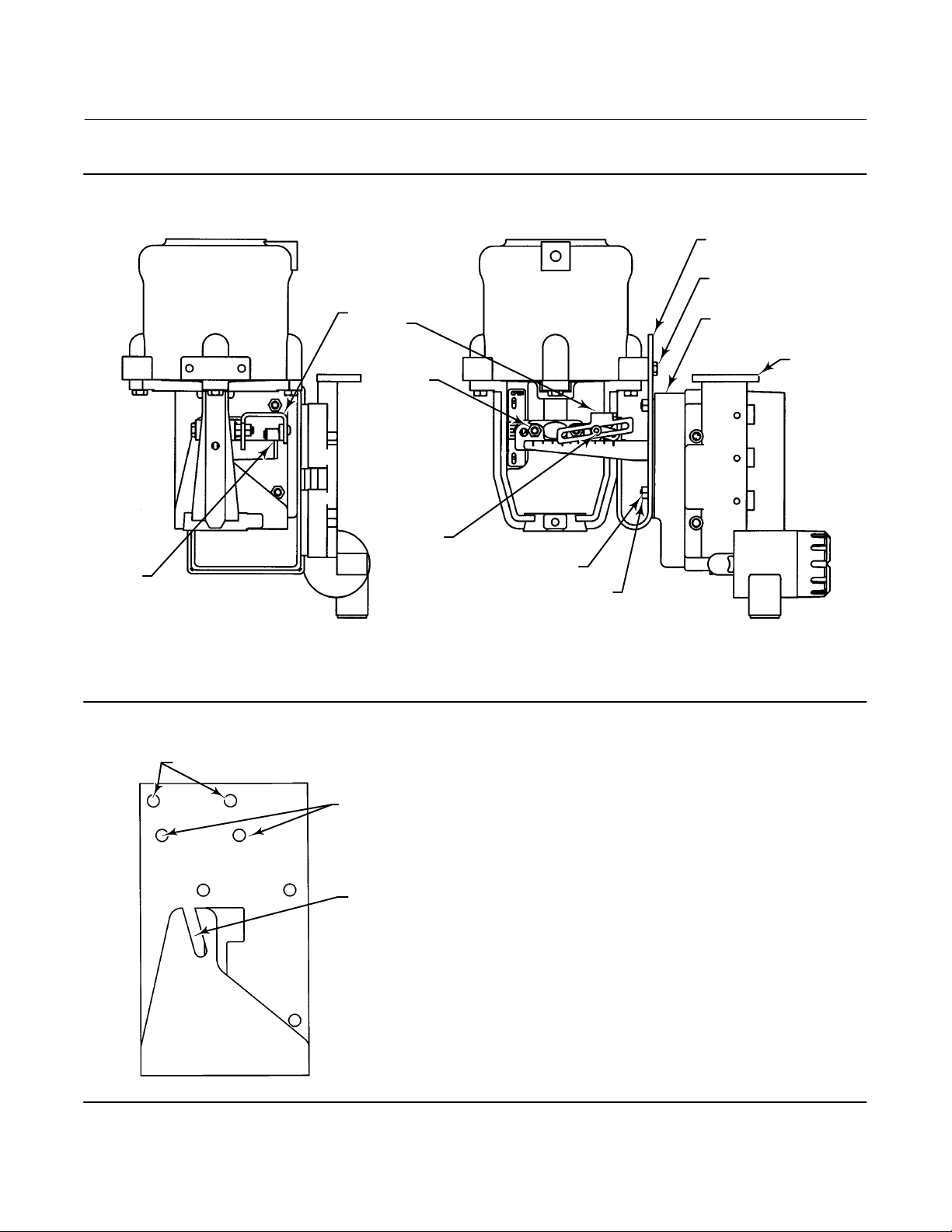
Mounting 3611JP and 3621JP on 585 and 585R Size 100 Actuators
Refer to figure 4 for part locations. Refer to figure 29 for key number locations unless otherwise indicated.
14

Instruction Manual
D200149X012
3610J and 3620J Positioners
Figure 4. Typical Mounting Details for Fisher 3611JP and 3621JP Positioners on 585 Actuators
BUTTON HEAD
SCREW (KEY 173)
POSITIONER
COVER (KEY 41)
January 2015
49A3788‐A
A3231‐2 / IL
STEM
BRACKET SLOTS
FEEDBACK LEVER
ASSEMBLY (KEY 117
OR KEY 170)
CONTROL VALVE ASSEMBLY WITH ACTUATOR FRONT YOKE COVER PLATE REMOVED
CAPTIVE
COVER SCREWS
3611JP
POSITIONER
POSITIONER
ADAPTER
(KEY 113)
1. Refer to the appropriate actuator instruction manual. Loosen the four screws, and remove the front yoke cover
plate from the actuator.
2. Stroke the actuator from the top stop to the bottom stop, and record the travel distance.
3. Loosen the four captive cover screws and remove the positioner cover (key 41, figure 28).
4. Refer to the appropriate actuator instruction manual. Loosen the four screws, and remove the actuator blanking
plate.
5. Attach the positioner adapter (key 113) to the actuator with four socket head screws (key 54).
6. Disconnect the positioner range spring (key 150, figure 25) from the range spring hanger (key 130, figure 25).
7. Attach the roller (key 175) and washers (key 184) to the adjuster assembly (key 174) and secure with the retaining
ring (key 172).
8. Apply pressure to the actuator piston and move the actuator to approximately the mid‐travel position.
9. Install the positioner on the actuator so the feedback lever assembly (key 170) is under the stem bracket and secure
the positioner to the adapter (key 113) with the four socket head screws (key 54).
15

3610J and 3620J Positioners
January 2015
10. With the actuator still at mid‐travel and the top edge of the feedback lever assembly perpendicular to the actuator
stem, install the adjuster assembly/roller in the appropriate stem bracket slot with the button head screw (key 173)
so the roller is centered over the correct actuator travel marked on the feedback lever assembly (key 170) as shown
in figure 4.
11. Tighten the button head screw (key 173) and replace the range spring (key 150, figure 25).
12. For size 100 actuators with greater than a 51 mm (2 inch) travel, install the feedback lever spring (key 185).
13. Replace the positioner cover.
14. Replace the front actuator cover plate.
15. Discard the actuator blanking plate and the four screws.
Instruction Manual
D200149X012
Mounting 3611JP and 3621JP on 585C and 585CR Size 25 and 50
Actuators
The 3611JP pneumatic positioner and the 3621JP electro‐pneumatic positioner can be mounted on either a 585C or
585CR piston actuator. A positioner adaptor (key 113) attaches to the back of the positioner and serves as the
interface to the mounting bracket (key 194). Refer to the 585C and 585CR actuators instruction manual
(D102087X012) for additional information on the actuator.
Refer to figure 5 for parts identification.
1. Stroke the actuator from the top stop to the bottom stop, and record the travel distance.
2. Loosen the four captive cover screws and remove the positioner cover (key 41, figure 28).
3. Mount the stem bracket (key 195) to the actuator with two hex nuts (key 197).
4. Disconnect the positioner range spring (key 150, figure 25) from the range spring hanger (key 130, figure 25).
5. Attach the feedback roller (key 175) to the stem bracket (key 195) with the button head screw (key 173).
6. Attach the positioner adaptor (key 113) to the mounting bracket (key 194) with four hex nuts (key 197) and four
hex socket cap screws (key 54).
7. Remove the positioner cover. Attach the 3611JP or 3621JP positioner to the positioner adaptor/mounting bracket
assembly with four hex socket cap screws (key 54).
8. Apply pressure to the actuator piston and move the actuator to approximately the mid‐travel position.
9. Thread one of the three hex head cap screws (key 196) into the yoke leg threaded hole approximately two (2) turns.
10. Install the assembly from step 7 to the 585C or 585CR actuator by sliding the mounting bracket slot (see figure 6)
onto the yoke leg cap screw. As you attach this assembly to the actuator, center the spring‐loaded feedback arm
under the feedback roller (key 175) on the stem bracket (key 195). Align the mounting bracket top holes (see
figure 6) with the cylinder holes and install the remaining two hex head cap screws (key 196). Tighten all screws.
11. With the actuator still at mid travel and the top edge of the feedback lever assembly perpendicular to the actuator
stem, install the adjuster assembly/roller in the appropriate stem bracket slot with the button head screw (key 173)
so the roller (key 175) is centered over the correct actuator travel marked on the feedback lever assembly.
12. Tighten the feedback roller button head screw (key 173) and replace the range spring (key 150, figure 25).
13. Replace the positioner cover.
16
Instruction Manual
3610J and 3620J Positioners
D200149X012
Figure 5. Typical Mounting Details for Fisher 3611JP and 3621JP Positioners on 585C Actuator
STEM BRACKET
(KEY 195)
HEX NUT
(KEY 197)
FEEDBACK ROLLER
BUTTON HEAD
SCREW
FEEDBACK
ROLLER
(KEY 175)
A6841 / IL
(KEY 173)
HEX SOCKET CAP
SCREW (KEY 54)
HEX NUT
(KEY 197)
January 2015
POSITIONER MOUNTING
BRACKET (KEY 194)
HEX HEAD CAP SCREW
(KEY 196)
POSITIONER ADAPTOR
(KEY 113)
3621JP
POSITIONER
Figure 6. Positioner Mounting Bracket
MOUNTING HOLES FOR SIZE 50 ACTUATOR
A6840/IL
MOUNTING HOLES
FOR SIZE 25 ACTUATOR
MOUNTING BRACKET SLOT
17
3610J and 3620J Positioners
January 2015
Instruction Manual
D200149X012
Installing the 3622 Electro‐Pneumatic Converter
If installing the converter on an existing pneumatic positioner, refer to the Gauge Block Disassembly procedures in the
Maintenance section. The converter module replaces the original pneumatic gauge block. Refer to the 3622
Electro-pneumatic Converter Assembly procedure to install the converter. When calibrating the electro‐pneumatic
positioner for a 4 to 20 milliampere DC input range, use the range spring hole that corresponds to a 0.2 to 1.0 bar (3 to
15 psig) input range [0.8 bar (12 psig) span]. See tables 10 and 11 and figure 15 for the range spring and range spring
hole selection.
Changing Positioner Types
All 3610J and 3620J positioners have the same basic construction. For 3611JP or 3621JP, a parallel flexure (key 179,
figure 13) is added (not required on 585 size 100 actuator). When changing positioner types, other parts may require
changing, such as the nozzle assembly (key 116, figure 25), the feedback lever assembly (key 117 or 170, figure 29),
and the range spring (key 150, figure 25). Refer to the Parts List for part number identification. Changing parts may
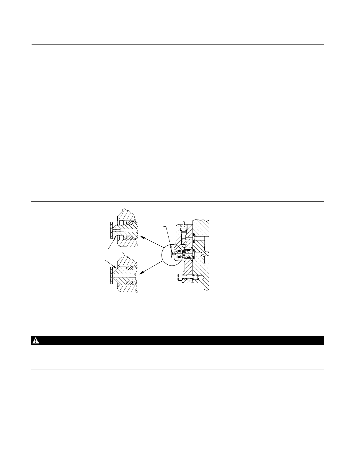
require partial disassembly and reassembly as described in the Maintenance section. Figure 7 illustrates the slight
difference in nozzle assemblies between the single‐acting (3610J and 3620J) and double‐acting (3610JP, 3620JP,
3611JP and 3621JP) positioners. See the Changing Positioner Types procedure in the Maintenance section for
additional information.
Figure 7. Nozzle Block Assembly
3610JP, 3611JP, 3620JP
AND 3621JP POSITIONERS
OFFSET TAPER
STRAIGHT TAPER
3610J AND 3620J POSITIONERS
36A5654‐A
A3234‐1/IL
FLAPPER
Pressure Connections
WARNING
The positioner is capable of providing full supply pressure to connected equipment. To avoid personal injury or equipment
damage caused by parts bursting from system overpressure, make sure the supply pressure never exceeds the maximum
safe working pressure of any connected equipment.
To complete the installation of a 3610J or 3620J positioner requires connecting tubing and fittings between the
positioner and the actuator. The fittings, tubing, and mounting parts required depend on the type number and
optional equipment: such as filter, regulator, and bypass valve. Positioner pressure connection locations are shown in
figure 8. All pressure connections to the 3610J and 3620J positioners are 1/4 NPT internal. Use 3/8‐inch tubing or
1/4‐inch pipe for all tubing connections. Refer to the Vent Connection section for remote vent connections.
18

Instruction Manual
D200149X012
3610J and 3620J Positioners
January 2015
Supply Connection
WARNING
Severe personal injury or property damage may occur from process instability if the instrument supply medium is not
clean, dry and oil‐free air, and noncorrosive gas. While use and regular maintenance of a filter that removes particles larger
than 40 micrometers in diameter will suffice in most applications, check with an Emerson Process Management field office
and industry instrument air quality standards for use with corrosive gas or if you are unsure about the proper amount or
method of air filtration or filter maintenance.
WARNING
3620J, 3620JP, 3621JP positioners and the 3622 electro‐pneumatic converter do not meet third party approvals for use with
natural gas as the supply medium. Use of natural gas as the supply medium can result in personal injury or property
damage from fire or explosion.
Supply pressure must be clean, dry, and oil‐free air or noncorrosive gas. Use of a 67CFR filter regulator with standard 5
micrometer filter, or equivalent, to filter and regulate supply air should suffice in most applications. The 67CFR filter
regulator can be integrally mounted with the positioner. Use 3/8‐inch tubing or 1/4‐inch pipe for the supply line.
CAUTION
To avoid equipment damage caused by excessive pressure, do not exceed the maximum pressure rating of the actuator or
positioner. Refer to the appropriate instruction manual to determine the maximum pressure rating of the actuator, and to
table 1 for the maximum pressure rating of the positioner.
The supply pressure should be high enough to permit setting the regulator 0.3 bar (5 psi) above the upper limit of the
appropriate pressure range, for example: 1.4 bar (20 psig) for a 0.2 to 1.0 bar (3 to 15 psig) range. However, do not
exceed the maximum allowable supply pressure of 10.3 bar (150 psig) nor the pressure rating of any connected
equipment.
Output Connections
For the 3610J or 3620J positioner, the OUTPUT A connection must be plugged. Connect the OUTPUT B connection to
the actuator diaphragm casing connection. Figure 8 shows a positioner with a bypass valve. When the bypass valve is
used, connect the OUTPUT connection on the bypass valve to the diaphragm casing connection on the actuator. A
manifold in the bypass body adapter internally connects OUTPUT B to the bypass valve.
Use 3/8‐inch tubing between the actuator and the positioner.
For the 3610JP or 3620JP positioner, connect the OUTPUT A connection to the lower actuator cylinder connection and
the OUTPUT B connection to the upper actuator cylinder connection. Figure 1 shows the positioner connected to a
piston actuator. Use 3/8‐inch tubing between the actuator and positioner.
For the 3611JP or 3621JP positioner, connect the OUTPUT A connection to the lower actuator cylinder connection and
the OUTPUT B connection to the upper actuator cylinder connection. Figure 2 shows the positioner connected to a
585C actuator. Use 3/8‐inch tubing between the actuator and the positioner.
19
3610J and 3620J Positioners
January 2015
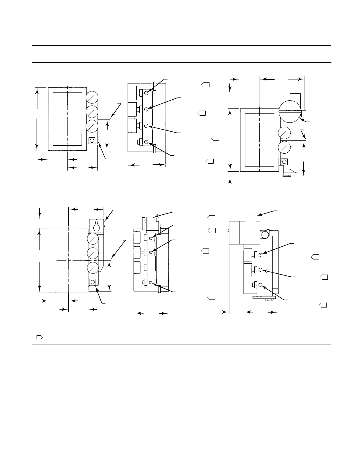
Figure 8. Typical Mounting Dimensions and Connections
INSTRUMENT
CONNECTION
Instruction Manual
D200149X012
63.5
1
(2.50)
153.9
(6.06)
208
(8.19)
19A1442‐D
31.8
(1.25)
208
(8.19)
CENTERLINE
OF BODY
103.9
(4.09)
63.5
(2.50)
100.1
(3.94)
GAUGE
BLOCK
111.3
(4.38)
TYPICAL 3610J POSITIONER WITHOUT BYPASS VALVE
119.1
(4.69)
BYPASS
VALVE
CENTERLINE
OF BODY
OUTPUT A
CONNECTION
(PLUGGED ON
3610J)
OUTPUT B
CONNECTION
SUPPLY
CONNECTION
OUTPUT B
CONNECTION
INSTRUMENT
CONNECTION
OUTPUT A
CONNECTION
(PLUGGED)
49.3
(1.94)
1
3622
CENTERLINE
208
(8.19)
1
1
17.5
(0.69)
1/2 NPT
1
1
1
CONDUIT
CONNECTION
OF BODY
122.2
(4.81)
OUTPUT A
CONNECTION
(PLUGGED ON
1
3620J)
103.9
(4.09)
63.5
(2.50)
19A1444‐C
NOTE:
INSTRUMENT, OUTPUT, AND SUPPLY CONNECTIONS ARE 1/4 NPT
1
C0681‐3 / IL
63.5
(2.50)
3610J POSITIONER WITH BYPASS ASSEMBLY
GAUGE
BLOCK
111.3
(4.38)
SUPPLY
CONNECTION
1
50.8
(2.00)
11B2612‐E
111.3
(4.38)
3620J OR 3620JP POSITIONER
OUTPUT B
CONNECTION
SUPPLY
CONNECTION
mm
(INCH)
Instrument Connection
Use 3/8‐inch tubing to connect the output from the control device to the INSTRUMENT connection on a pneumatic
positioner. For the electro‐pneumatic positioner, refer to the Electrical Connections section.
1
1
20
 Loading...