


Instruction Manual |
249 Cageless Sensors |
D200100X012 |
December 2012 |
|
|
Fisherr 249 Cageless Displacer Sensors
Contents |
|
Introduction . . . . . . . . . . . . . . . . . . . . . . . . . . . . . |
. . . . 1 |
Scope of Manual . . . . . . . . . . . . . . . . . . . . . . . . . |
. . . . 1 |
Description . . . . . . . . . . . . . . . . . . . . . . . . . . . . . . |
. . . 1 |
Type Number Description . . . . . . . . . . . . . . . . . . |
. . . 2 |
Educational Services . . . . . . . . . . . . . . . . . . . . . . |
. . . 3 |
Maintenance . . . . . . . . . . . . . . . . . . . . . . . . . . . . . . |
. . . 3 |
Removing the Displacer and Stem . . . . . . . . . . . |
. . . 4 |
Replacing the Displacer, Cotter Spring, |
|
Stem End Piece, and Displacer Spud . . . . . . . |
. . . 6 |
Replacing the Displacer Rod/Driver Assembly |
. . . . 7 |
Replacing the Torque Tube . . . . . . . . . . . . . . . . . |
. . . 8 |
Replacing the Torque Tube Arm and |
|
Changing the Mounting . . . . . . . . . . . . . . . . . |
. . . 9 |
Simulation of Process Conditions for |
|
Calibration of Fisher Level Controllers |
|
and Transmitters . . . . . . . . . . . . . . . . . . . . . . . . . . |
. . 10 |
Parts Ordering . . . . . . . . . . . . . . . . . . . . . . . . . . . . . |
. . 10 |
Parts Kits . . . . . . . . . . . . . . . . . . . . . . . . . . . . . . . . . |
. . 11 |
Parts List . . . . . . . . . . . . . . . . . . . . . . . . . . . . . . . . . |
. . 11 |
Sensor Common Parts . . . . . . . . . . . . . . . . . . . . . |
. . 11 |
Figure 1. Fisher 249V Sensor with FIELDVUE™ DLC3010/DLC3020f Digital Level Controller
W3120 3
Introduction
Scope of Manual
This instruction manual includes maintenance and parts ordering information for Fisher 249 cageless displacer sensors.
Although a 249 sensor is usually shipped with attached controller or transmitter, this manual does not include operation, installation, calibration, maintenance, and parts ordering information for the controller/transmitter or for the complete unit. For this information, refer to the appropriate controller/ transmitter instruction manual.
Do not install, operate, or maintain a 249 sensor without being fully trained and qualified in valve, actuator, and accessory installation, operation, and maintenance. To avoid personal injury or property damage, it is important to carefully read, understand, and follow all of the contents of this manual, including all safety cautions and warnings. If you have any questions about these instructions, contact your Emerson Process Management sales office.
Description
249 sensors are designed to measure liquid level, interface level, or density/specific gravity inside a process vessel.
www.Fisher.com
249 Cageless Sensors |
Instruction Manual |
December 2012 |
D200100X012 |
|
|
A torque tube assembly (figure 2) and displacer provide an indication of liquid level, interface level, or density/specific gravity. The torque tube assembly consists of a hollow torque tube with a shaft welded inside it at one end and protruding from it at the other end.
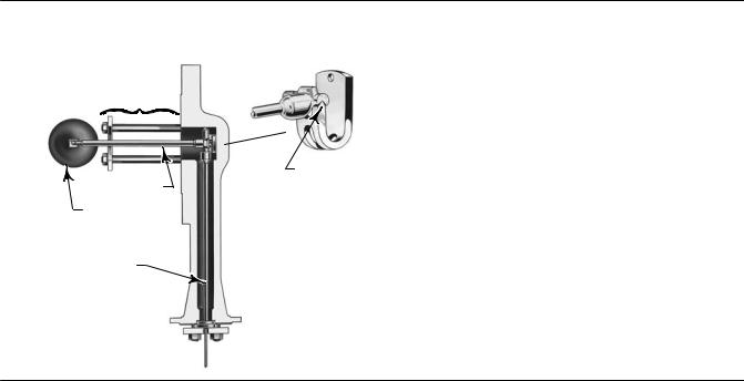
Figure 2. Typical Side Mounted Cageless Displacer
TRAVEL STOP ASSEMBLY
W1800 1 |
KNIFE EDGE BEARING |
DISPLACER ROD |
|
DISPLACER |
|
TORQUE TUBE |
|
W0172 1
The unconnected end of the tube is sealed by a gasket and clamped rigidly to the torque tube arm, permitting the protruding end of the shaft to twist and therefore transmit rotary motion. This allows the interior of the torque tube to remain at atmospheric pressure, thus eliminating packing and the disadvantages of packing friction.
The displacer always exerts a downward force on one end of the displacer rod. The other end of the displacer rod rests on the knife edge of the driver bearing. A keyed shaft on the bearing end of the displacer fits into a socket on the outside of the welded end of the of the torque tube assembly.
A change in liquid level, interface level, or density/specific gravity buoys up the displacer by a force equal to the weight of the liquid displaced. Corresponding vertical movement of the displacer results in angular movement of the displacer rod around the knife edge. Since the torque tube assembly is a torsional spring which supports the displacer and determines the amount of movement of the displacer rod for a given displacement change, it will twist a specific amount for each increment of buoyancy change. This rotation is brought through the torque tube arm by the protruding rotary shaft. A controller or transmitter attached to the end of the rotary shaft converts the rotary motion into varying pneumatic or electric signals.
Unless otherwise noted, all NACE references are to NACE MR0175-2002.
Type Number Description
D 249BP—CL150, 300, 600 steel top mounted sensor
D 249CP—CL150, 300, 600 stainless steel top mounted sensor
2

Instruction Manual |
249 Cageless Sensors |
D200100X012 |
December 2012 |
|
|
D 249P—CL150, 300, 600, 900 or 1500 steel top mounted sensor
Note
249P CL150, 300, and 600 sensors are only available in Europe.
D 249V—CL125 or 250 cast iron or CL150, 300, 600, 900, or 1500 steel side mounted sensor
Note
249V sensors are only available in Europe.
All cageless 249 sensors have flanged connections.
The Parts List section shows some 249 sizes by construction, standard displacer lengths, and standard materials and table 1 contains displacer and torque tube materials. However, 249 parts are available in a wide variety of materials of construction, part dimensions, and other specifications. Contact your Emerson Process Management sales office for assistance in selection of specific materials, dimensions, and specifications.
Table 1. Displacer and Torque Tube Materials
Part |
Standard Material |
Other Materials |
|
Displacer |
304 Stainless Steel |
316 Stainless Steel, N10276, N04400, Plastic, and Special Alloys |
|
|
|
|
|
Displacer Stem, Driver Bearing, |
316 Stainless Steel |
N10276, N04400, other Austenitic Stainless Steels, and Special Alloys |
|
Displacer Rod and Driver |
|||
|
|
||
|
|
|
|
Torque Tube |
N05500(1) |
316 Stainless Steel, N06600, N10276 |
1. N05500 is not recommended for spring applications above 232_C (450_F). Contact your Emerson Process Management sales office or application engineer if temperatures exceeding this limit are required.
Educational Services
For information on available courses for 249 displacer sensors, as well as a variety of other products, contact:
Emerson Process Management Educational Services, Registration P.O. Box 190; 301 S. 1st Ave. Marshalltown, IA 50158-2823 Phone: 800-338-8158 or
Phone: 641-754-3771 FAX: 641-754-3431
e mail: education@emerson.com
Maintenance
Sensor parts are subject to normal wear and must be inspected regularly and replaced as necessary. The frequency of inspection and replacement depends upon the severity of service conditions.
3

249 Cageless Sensors |
Instruction Manual |
December 2012 |
D200100X012 |
|
|

 WARNING
Always wear protective clothing, gloves, and eyewear when performing any maintenance operations to avoid personal injury.
Avoid personal injury or property damage resulting from the sudden release of pressure. Before performing any maintenance procedure:
D Relieve any process pressure in the process vessel where the 249 sensor is installed.
D Drain the process liquid from the process vessel.
D Shut off any electrical or pneumatic input to the controller or transmitter attached to the 249 sensor and vent any pneumatic supply pressure.
D Use caution when loosening flange bolting or pipe plugs (key 26).
D Remove the controller or transmitter from the torque tube arm (key 3).
Before performing any maintenance procedure requiring the handling of the displacer, inspect the displacer (key 10) to make sure process pressure or liquids have not penetrated the displacer.
The displacer in this unit is a sealed container. If penetrated by process pressure or liquid, the displacer may hold pressure or hazardous liquid for an extended period. A displacer that has been penetrated by process pressure or liquid may contain:
D pressure as a result of being in a pressurized vessel.
D liquid that becomes pressurized due to a change in temperature.
D liquid that is flammable, hazardous, or corrosive.
Sudden release of pressure, contact with hazardous liquid, fire, or explosion, which might result in personal injury or property damage, can occur if a displacer that is retaining pressure or process liquid is punctured, subjected to heat, or repaired.
Handle the displacer with care. Consider the characteristics of the specific process liquid in use.
Check with your process or safety engineer for any additional measures that must be taken to protect against process media.
Note
Except for gaskets (keys 13, 14), trouble symptoms peculiar to specific parts are discussed in the following sections. Each section is specific to these parts. Regardless of location, gasket failure is indicated by leakage in the gasket area. Every time a gasket is removed, replace it with a new one upon reassembly.
The procedures below apply to all sensor types except where indicated. Key numbers used are shown in the following illustrations:
D 249BP—figure 5
D 249CP—figure 6
D 249P—figure 7
D 249V—figure 8
Removing the Displacer and Stem
The displacer (key 10) is a sealed container. If the displacer has been penetrated by process pressure or liquid, it may hold pressure or hazardous liquid for an extended period.
4

Instruction Manual |
249 Cageless Sensors |
D200100X012 |
December 2012 |
|
|
Process residue buildup on the displacer and stem (key 24) may change displacer weight or displacement. A bent stem or a dented or corroded displacer can impair performance.
If the displacer rests against the travel stop, appears to be overweight, or causes output drift or other output inaccuracies, it may have been penetrated by process pressure or liquid. Such a displacer may contain pressure because it was in a pressurized vessel, may contain process liquid that becomes pressurized due to a change in temperature, and may contain process liquid that is flammable, hazardous, or corrosive.

 WARNING
Sudden release of pressure, contact with hazardous liquid, fire, or explosion, which may result in personal injury or property damage, can occur if a displacer that is retaining pressure or process liquid is punctured, subjected to heat, or repaired.
Handle the displacer with care.
Note
On the 249V, 249P, and 249BP with travel stop, the displacer must come out with the sensor head (key 2) or torque tube arm (key 3) before being completely disconnected from the displacer rod (key 7). If separating the displacer and displacer rod, remove the cotter spring (key 11).
CAUTION
Be careful not to let the displacer slip and drop into the bottom of the process vessel, as displacer damage could result.
1.Before starting any maintenance procedure, be sure the following safety actions are completed.
D Relieve process pressure in the process vessel where the 249 sensor is installed.
D Drain the process liquid from the process vessel.
D Shut off any electrical or pneumatic input to the controller or transmitter attached to the 249 sensor and vent any pneumatic supply pressure. Remove the controller or transmitter from the torque tube arm.
D Use caution when loosening flange bolting or pipe plugs.
D Be sure process pressure or liquids have not penetrated the displacer.
2.Support the sensor head (key 2) and the torque tube arm (key 3). Remove the bolting that holds the sensor head to the process vessel.
CAUTION
When removing a sensor from a process vessel, the displacer may remain attached to the displacer rod and be lifted out with the sensor head (key 2) when the sensor head is removed. If separating the displacer and displacer rod before removing the sensor head, remove the cotter spring (key 11). If the displacer comes out with the head or torque tube arm, be careful not to damage the displacer or bend the stem when setting the head or arm down.
5
 Loading...