


Instruction Manual |
1052 Size 70 Actuators |
D104083X012 |
February 2015 |
|
|
Fisherr 1052 Size 70 Diaphragm Rotary Actuator
Contents
Introduction . . . . . . . . . . . . . . . . . . . . . . . . . . . . . . . . . 1
Scope of Manual . . . . . . . . . . . . . . . . . . . . . . . . . . . . . 1
Description . . . . . . . . . . . . . . . . . . . . . . . . . . . . . . . . . 3
Specifications . . . . . . . . . . . . . . . . . . . . . . . . . . . . . . . 3
Educational Services . . . . . . . . . . . . . . . . . . . . . . . . . 3
Installation . . . . . . . . . . . . . . . . . . . . . . . . . . . . . . . . . . 3
Actuator Mounting . . . . . . . . . . . . . . . . . . . . . . . . . . 4
Valve Flow Direction . . . . . . . . . . . . . . . . . . . . . . . . . 7
Loading Connection . . . . . . . . . . . . . . . . . . . . . . . . . . 7
Turnbuckle Adjustment . . . . . . . . . . . . . . . . . . . . . . . 8
1052 Spring Adjustment . . . . . . . . . . . . . . . . . . . . . . 9
Initial Setting . . . . . . . . . . . . . . . . . . . . . . . . . . . . 9
Stroking Range . . . . . . . . . . . . . . . . . . . . . . . . . . 9
Principle of Operation . . . . . . . . . . . . . . . . . . . . . . . . 9
Maintenance . . . . . . . . . . . . . . . . . . . . . . . . . . . . . . . . 10
Disassembly . . . . . . . . . . . . . . . . . . . . . . . . . . . . . . . 10
Assembly . . . . . . . . . . . . . . . . . . . . . . . . . . . . . . . . . . 12
Changing Actuator Mounting . . . . . . . . . . . . . . . . . 14
Top Mounted Handwheels and
Adjustable Travel Stops . . . . . . . . . . . . . . . . . . . . . . . 15
Principle of Operation for Handwheels . . . . . . . . . 15
Handwheel Maintenance and Adjustable
Travel Stop . . . . . . . . . . . . . . . . . . . . . . . . . . . . . . 16
Locking Mechanism . . . . . . . . . . . . . . . . . . . . . . . . . . 18
Installing the Locking Mechanism . . . . . . . . . . . . . 18
Operating the Locking Mechanism . . . . . . . . . . . . 19
Pipe Away Vent . . . . . . . . . . . . . . . . . . . . . . . . . . . . . . 21
Parts Ordering . . . . . . . . . . . . . . . . . . . . . . . . . . . . . . . 22
Parts Reference . . . . . . . . . . . . . . . . . . . . . . . . . . . . . . 22
Figure 1. Fisher Vee Ball™ Valve with 1052 Actuator and FIELDVUE™ DVC6200 Digital Valve Controller
W8502-3
Introduction
Scope of Manual
This instruction manual includes installation, adjustment, maintenance, and parts ordering information for the Fisher 1052 (Size 70) pneumatic piston rotary actuator (see figure 1).
This instruction manual also provides information for the optional top mounted handwheel, up and down travel stops, locking mechanism, and pipe away vent.
www.Fisher.com

1052 Size 70 Actuators |
Instruction Manual |
February 2015 |
D104083X012 |
|
|
Table 1. 1052 Actuator Specifications
Operation
Direct Acting: Increasing loading pressure extends the diaphragm rod out of the spring barrel Service: For on off or throttling service with or without a positioner
Actuator Sizes
70
Maximum Diaphragm Sizing Pressure(1)
3.8 bar (55 psig)
Maximum Diaphragm Casing Pressure(3)
4.5 bar (65 psig)
Maximum Valve Shaft Rotation
Standard: 90 degrees rotation travel stop Optional: 60 or 75 degrees rotation travel stop
Valve Shaft Diameters, mm (Inches)
JÉ31.8 (1 1/4), JÉ38.1 (1 1/2), JÉ44.5 (1 3/4), or JÉ50.8 (2)
Stroking Time
Dependent on actuator size, rotation, spring rate, initial spring compression, and supply pressure. If stroking time is critical, consult your Emerson Process Management sales office
Material Temperature Capabilities(2)
NBR (Nitrile) Diaphragm: -40 to 82_C (-40 to 180_F) VMQ (Silicone) Diaphragm: -40 to 149_C (-40 to 300_F)
NBR O Rings: -40 to 82_C (-40 to 180_F), NBR O rings are used in optional top mounted handwheel, adjustable down travel stop, and adjustable up travel stop assemblies
Travel Indication
Graduated disk and pointer combination located on actuator end of valve shaft
Pressure Connections
Standard: 1/4 NPT internal thread Optional: JÉ1/2 or JÉ3/4 NPT internal, and
JÉ3/4 NPT internal thread for pipe away vent
Mounting Positions
See figure 3.
Approximate Weights
See table 2.
Additional Specifications
For casing pressure ranges and for material identification of the parts, see the Parts List
1.Use this value to determine the maximum torque output allowed.
2.The pressure/temperature limits in this manual and any applicable standard or code limitation for valve should not be exceeded.
3.This maximum casing pressure is not to be used for normal operating pressure. Its purpose is to allow for typical regulator supply settings and/or relief valve tolerances.
Instructions for the control valve, positioner, accessories, and other sizes of actuators are covered in separate instruction manuals.
Top Mounted handwheels can be applied for infrequent service as a manual handwheel actuator. Also, an adjustable up travel stop can be added to the actuator to limit its stroke in the upward direction, or an adjustable down travel stop can be added to limit actuator stroke in the downward direction.
Do not install, operate, or maintain a 1052 actuator without being fully trained and qualified in valve, actuator, and accessory installation, operation, and maintenance. To avoid personal injury or property damage, it is important to carefully read, understand, and follow all the contents of this manual, including all safety cautions and warnings. If you have any questions about these instructions, contact your Emerson Process Management sales office. before proceeding.
2
Instruction Manual |
1052 Size 70 Actuators |
D104083X012 |
February 2015 |
|
|
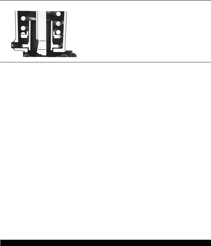
Figure 2. Typical 1052 Actuator Adjustable Spring Seat
 SPRING
 SPRING SEAT
 SPRING ADJUSTER
W4742 1
Description
1052 diaphragm rotary actuators are pneumatic spring return actuators for use with rotary shaft control valves. It can be used for on off service, or it can be used for throttling service when equipped with or without a valve positioner. The 1052 actuator spring is adjustable (see figure 2).
Table 2. Approximate Actuator Weights
SIZE |
|
1052 |
TOP MOUNTED HANDWHEEL |
||
Kg |
|
Lb |
Kg |
Lb |
|
|
|
||||
70 |
123 |
|
272 |
21 |
47 |
|
|
|
|
|
|
Specifications
Specifications are shown in table 1. Specifications for actuator operation, as it originally comes from the factory, are stamped on the nameplate attached to the actuator.
Educational Services
For information on available courses for Fisher 1052 size 70 rotary actuators, as well as a variety of other products, contact:
Emerson Process Management
Educational Services - Registration
Phone: 1-641-754-3771 or 1-800-338-8158
E-mail: education@emerson.com
http://www.emersonprocess.com/education
Installation
When an actuator and valve body are shipped together, the actuator is normally mounted on the valve. Follow the valve body instructions when installing the control valve in the pipeline, and then perform the procedures presented in the Loading Connection section. If the actuator is shipped separately or if it is necessary to mount the actuator on the valve, perform the procedures presented in the Actuator Mounting section. And, if the actuator requires a pipe away vent, or if a retrofit pipe away kit needs to be installed, refer to the Pipe Away Vent section.

 WARNING
Always wear protective gloves, clothing, and eyewear when performing any installation operations. Be aware of pinching parts during installation operations.
3

1052 Size 70 Actuators |
Instruction Manual |
February 2015 |
D104083X012 |
|
|
Check with your process or safety engineer for any additional measures that must be taken to protect against process media.
If installing into an existing application, also refer to the WARNING at the beginning of the Maintenance section in this instruction manual.
Table 3. Recommended Bolting Torques
Description, Key Number |
Size |
NSm |
lbfSft |
|
Diaphragm Casing, 5 |
3/8 24 |
27 |
20 |
|
|
|
|
|
|
Casing to spring barrel, 7 |
1/2 13 |
102 |
75 |
|
|
|
|
|
|
Diaphragm to rod, 9 |
3/4 16 |
102 |
75 |
|
|
|
|
|
|
Rod end bearing, 16 |
3/4 16 |
102 |
75 |
|
|
|
|
|
|
Turnbuckle to lever, 18 |
3/4 10 |
271 |
200 |
|
|
|
|
|
|
Spring barrel to housing, 21 |
5/8 18 |
68 |
50 |
|
|
|
|
|
|
Housing to yoke, 23 |
1/2 13 |
81 |
60 |
|
|
|
|
|
|
Travel stop to lever, 28 |
3/4 10 |
271 |
200 |
|
|
|
|
|
|
Side of housing, 34 |
1/2 13 |
81 |
60 |
|
4200/PMV |
||||
|
|
|
||
|
|
|
|
|
Handwheel top, 54 |
|
34 |
25 |
|
|
|
|
|
|
Diaphragm head to rod/Adjustable down travel stop, 54 |
3/4 16 |
69 |
51 |
|
|
|
|
|
|
Rod end to turnbuckle, 58 |
7/8 14 LH |
163 |
120 |
|
|
|
|
|
|
Handwheel to actuator, 141 |
1/2 13 |
81 |
60 |
|
|
|
|
|
CAUTION
To avoid parts damage, do not use an operating pressure that exceeds the Maximum Diaphragm Casing Pressure (table 1) or produces a torque greater than the Maximum Allowable Valve Shaft Torque. Use pressure limiting or pressure relieving devices to prevent the diaphragm casing pressure from exceeding its limit.
To avoid parts damage, do not stroke the actuator while cover (key 33) is off.
Actuator Mounting
Use the following steps to connect a valve and an actuator. Key numbers are shown in figure 8.

 WARNING
To avoid personal injury, perform the steps in the WARNING at the beginning of the Maintenance section to isolate the control valve and actuator.
1.Unscrew cap screws and washers (keys 34 and 63), and remove the cover (key 33).
2.Refer to figure 3 for available mounting styles and positions. When mounting on a Vee Ball V150, V200 or V300 valve, check the valve manual to determine if it is Series B. The actuator is normally positioned vertically with the valve in a horizontal pipeline (see figure 3).
4

Instruction Manual |
|
|
|
|
|
1052 Size 70 Actuators |
|
||
D104083X012 |
|
|
|
|
|
|
|
February 2015 |
|
|
|
|
|
|
|
|
|
|
|
|
|
|
|
|
|
|
|
|
|
|
|
|
VALVE SERIES OR DESIGN |
|
VALVE SERIES OR DESIGN |
|
|||
MOUNTING |
ACTION(1) |
BALL/PLUG |
V250 |
V150, V200 & V300 |
CV500 and |
DISK/BALL |
V250 |
8532, 8560 |
|
|
|
ROTATION TO |
V500 |
ROTATION TO |
8580, and |
|
|||
|
|
CLOSE |
|
|
CLOSE |
|
8590 |
|
|
|
|
|
|
|
|
|
|||
Right Hand |
PDTC |
CCW(3) |
A |
A |
A |
CW |
NA |
B |
|
PDTO |
CCW |
B |
B |
B |
CW |
NA |
A |
|
|
|
|
||||||||
|
|
|
|
|
|
|
|
|
|
Left Hand |
PDTC |
CCW |
NA |
D |
D |
CW |
C |
C |
|
PDTO |
CCW |
NA |
C |
C |
CW |
D |
D |
|
|
|
|
||||||||
|
|
|
|
|
|
|
|
|
|
Left Hand |
PDTC |
CW(4) |
NA |
C |
NA |
NA |
NA |
NA |
|
(Optional)(2) |
PDTO |
CW |
NA |
D |
NA |
NA |
NA |
NA |
|
1. PDTC—Push down to close, and PDTO—Push down to open.
2. A left hand ball will be required for the NPS 3 through 12 Series B and the NPS 14 to 20, with or without attenuator. 3. CCW = counterclockwise
4. CW = clockwise

 WARNING
To avoid personal injury or property damage, the 1052 size 70 actuator, due to its weight, must be externally supported if mounted in the horizontal position.
3.When mounting the actuators, make sure that the bushing (key 67) and valve shaft are in line so that the bushing will slide onto the valve shaft without damage.
4.Mount the actuator on the valve body and secure it with the valve mounting screws. The torque for 1/2 to 1 inch shafts is 88 NSm (65 lbfSft); for 1 1/4 to 1 1/2 inch shafts is 136 NSm (100 lbfSft); for 1 3/4 to 2 inch shafts is 183 NSm (135 lbfSft).
CAUTION
Exceeding any torque requirement may impair the safe operation of this actuator by causing broken or damaged parts. Refer to table 3 for the bolting torque requirements.
5.Screw the left hand threaded locknut (key 58) onto the diaphragm rod (key 10) as far as possible.
6.Screw the turnbuckle (key 57) as far as it will go onto the actuator rod.
7.Screw the locknut (key 16) as far as it will go onto the rod end bearing (key 17). Thread this assembly completely into the turnbuckle (key 57).
8.If the lever (key 27) is attached to the rod end bearing, remove the cap screw and hex nut (keys 18 and 19).
9.If the 1052 spring adjustment has been changed, complete the Initial Setting portion of the 1052 Spring Adjustment section before proceeding.
10.Consult the appropriate valve instruction manual's Installation section for lever/valve shaft orientation marks, and slide the lever into place (see figure 4). Clamp with the cap screw (key 28).
11.Rotate the lever (key 27) to align with the rod end bearing (key 17). This connection can be aided by moving the actuator off its up travel stop with a regulated air source and adjusting the turnbuckle (key 57) slightly.
12.Apply sealant (key 77) or equivalent thread locking compound to the threads of the cap screw (key 18).
13.Connect the lever (key 27) and the rod end bearing (key 17) with the cap screw and hex nut (keys 18 and 19). Tighten the cap screw to the recommended bolt torque shown in table 3.
14.Note the valve position and direction of rotation. Position the travel indicator (key 37) accordingly.
a.If no handwheel actuator is to be used, position the travel indicator (key 37) according to the valve position just noted. Replace the cover (key 33), and secure with washers and cap screws (keys 34 and 63). If holes in the cover and housing (key 20) do not align, temporarily loosen the cap screws (key 23), and shift the housing slightly.
5

1052 Size 70 Actuators |
Instruction Manual |
February 2015 |
D104083X012 |
|
|
Figure 3. Mounting Styles and Positions for the 1052 Actuator
STYLE D
STYLE C
LEFT HAND
MOUNTING
STYLE B
STYLE A
RIGHT HAND
43A6505-A MOUNTING
A1584-3
STYLE A |
|
|
STYLE B |
|||||||
|
|
|
|
|
POSITION 1 |
|
|
|||
POSITION 1 |
1 |
|
|
|
1 |
|
|
|||
2 |
|
|
4 |
|
|
FLOW |
||||
|
|
|
|
|||||||
|
|
|
|
|
|
|
|
|||
4 |
|
|
|
|
2 |
|
|
|
|
|
3 |
|
|
|
|
3 |
|
|
|
|
|
RIGHT HAND MOUNTING |
||||||||||
STYLE D |
|
|
STYLE C |
|||||||
|
|
|
|
|
|
|
|
|
||
POSITION 1 |
|
|
|
|
POSITION 1 |
1 |
||||
|
1 |
|||||||||
|
|
|
|
|
|
|
|
|
|
|
FLOW
|
2 |
4 |
|
|
|
4 |
|
2 |
3 |
|
3 |
|
|
LEFT HAND MOUNTING |
NOTES: |
|
|
1 |
|
POSITION 1 IS STANDARD; POSITIONS 2 THROUGH 4 |
(SHOWN IN DOTTED LINES) ARE ALTERNATIVES.
CAUTION
To avoid parts damage, do not stroke the actuator while the cover (key 33) is off.
b.If a manual handwheel actuator is to be used, refer to the separate handwheel actuator instruction manual for mounting instructions.
15.Replace the cover (key 33), and secure with cap screws and washers (keys 34 and 63). If the holes in the cover and housing (key 20) do not align, use a regulated air source to move the actuator slightly off the up travel stop. If the hole alignment cannot be obtained in this manner, temporarily loosen the cap screws (key 23), and shift the housing slightly.
6
Instruction Manual |
1052 Size 70 Actuators |
D104083X012 |
February 2015 |
|
|
|
|
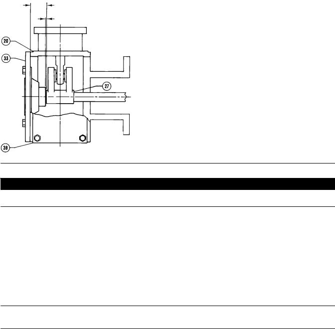
Figure 4. Lever Operating Clearance |
|
34.9 |
|
(1.375) |
|
OPERATING CLEARANCE |
1.6 |
(0.0625) |
mm (INCH)
13A6773 A
A1739 4
CAUTION
To avoid parts damage, do not stroke the actuator while the cover (key 33) is off.
16. Follow the instructions given in the Turnbuckle Adjustment section before proceeding to the Loading Connection section.
Valve Flow Direction
Valve construction can change the flow direction for a control valve assembly. It is important to observe the flow direction in all valve applications before installing the valve in the pipeline (see figure 3). Refer to the appropriate valve bulletin or instruction manual.
Note
Observe all warnings and cautions provided in the appropriate valve instruction manual Installation section.
Loading Connection
1.Connect the loading pressure piping to the pressure connection in the top of the diaphragm casing. Run either pipe or tubing between the pressure connection and the instrument. If necessary, remove the 1/4 inch bushing in the pressure connection to increase connection size.
7

1052 Size 70 Actuators |
Instruction Manual |
February 2015 |
D104083X012 |
|
|
2.Keep the length of pipe or tubing as short as possible to avoid transmission lag in the control signal. If an accessory (such as a volume booster or a valve positioner) is used, be sure that the accessory is properly connected to the actuator. If a valve positioner is part of the assembly, the pressure connection to the actuator will normally be made at the factory.
Table 4. Wrench Size Required for Turnbuckle Adjustment, Inches
|
ACTUATOR |
TURNBUCKLE |
LOWER LOCKNUT (KEY 16) |
UPPER LOCKNUT (KEY 58) |
|
Type |
|
Size |
(KEY 57) |
||
|
|
|
|||
1052 |
|
70 |
1 5/16 |
1 1/8 |
1 5/16 |
|
|
|
|
|
|
3.When the control valve is completely installed and connected to the instrument, check for correct action (air to open or air to close) to match the controlling instrument. For successful operation, the actuator stem and valve shaft must move freely in response to the loading pressure change on the diaphragm.
Adjustment
Turnbuckle Adjustment
Correct turnbuckle adjustment ensures that the valve is correctly closed when the actuator is against its travel stops. Key numbers are shown in figure 8.
For accurate adjustment to the zero degree valve disk or ball position, remove the valve from the pipeline. Refer to the valve instruction manual for instructions.
A regulated air supply will be required to stroke the actuator. Refer to table 4 for the sizes of the three open end wrenches required for this procedure.
1. Remove the access plate (key 59). Also remove the machine screws (key 60), if present.
Note
For the most accurate adjustment of the actuator, do not remove the cover (key 33) during this procedure.
2.Loosen the lower locknut (key 16).
3.Make sure the actuator housing (key 20) is clear of any tools or other instruments that could obstruct the actuator stroke path. Pressure the diaphragm casing enough to stroke the actuator down so that the left hand threaded upper locknut (key 58) is accessible through the access opening. Loosen the locknut.
4.Consult the appropriate valve instruction manual for determining the closed position of the valve. Then use one of the following:
a.Push down to close—Slowly stroke the actuator to the down travel stop. Adjust the turnbuckle (key 57) until the valve is in the closed position. Lock this adjustment with the left hand threaded locknut (key 58). Stroke the actuator to the mid travel position, and tighten the locknut (key 16).
b.Push down to open—Release all pressure from the diaphragm casing, making sure the diaphragm is against its up travel stop. Be sure that the optional handwheel is adjusted to its topmost position so that the zero position of the actuator and valve can be reached simultaneously. Check the valve position. Stroke the actuator so the turnbuckle (key 57) is accessible through the access opening. Adjust the linkage. Release pressure to the actuator, and check the new adjustment. Continue this procedure until the valve is in the closed position when the actuator is resting on its up travel stop. Stroke the actuator to the mid travel position, and tighten the locknut (key 16). Stroke the actuator, and tighten the left hand threaded locknut (key 58).
8

Instruction Manual |
1052 Size 70 Actuators |
D104083X012 |
February 2015 |
|
|
5.Replace the access plate (key 59).
6.Loosen the self tapping screws (key 38), adjust the travel indicator (key 37), and re tighten the self tapping screws.
1052 Spring Adjustment
Initial Setting
The 1052 nameplate specifies an initial spring setting, which is the initial setting adjusted into the actuator spring. Initial setting is the casing pressure at which the diaphragm and diaphragm rod begin to move away from the up travel stop with the actuator disconnected from the valve. (With the actuator connected to the valve and pressure applied to the valve, a higher pressure will be required to start actuator travel).
The initial setting was selected (based upon the service conditions specified when the actuator was ordered) so that, when the actuator and valve are in service, the valve will seat properly and full travel will be obtained within a diaphragm casing range of 0 to 2.3, 0 to 2.8, or 0 to 3.8 bar (0 to 33, 0 to 40, or 0 to 55 psig) depending on specific actuator size and construction.
If the actuator has been disassembled or if the spring adjustment was changed, and it is desired to match the initial setting stated on the nameplate, make sure the rod end bearing (key 17, figure 8) has been disconnected from the lever (key 27, figure 8). Adjust the spring so that the diaphragm rod just starts to travel at the spring set pressure specified on the nameplate.
Be sure the rod end bearing does not hit the lever as the diaphragm and diaphragm rod move away from the up travel stop. To adjust the spring, insert a round rod into one of the holes in the lower bearing seat (key 73, figure 8). Hole diameter is 19.1 mm (3/4 inch) for size 70 actuators. Rotate the bearing seat to move it toward the casing to increase initial setting or away from the casing to decrease initial setting (keys 1 and 2, figure 8).
Stroking Range
The initial spring setting listed on the nameplate has been determined to be the optimum setting, and it is not recommended to make spring adjustments that will cause this value to change or be exceeded. For push down to open valve action, the initial spring setting is the maximum allowable to provide the maximum spring closing force.
CAUTION
Any increase of this setting will over stress the spring at full travel and may shorten the fatigue life of the spring.
For push down to close valve action, the initial spring set has been determined to be the optimum balance between the air to close and the spring to open breakout torque.
If the 1052 actuator is to be changed from one valve action to another (i.e., push down to close to push down to open), first, refer to the table for key 11 in the Parts List section to determine the proper initial spring setting; then, adjust the unit according to the procedures in the Initial Settings portion of the 1052 Spring Adjustment section.
Principle of Operation
The diaphragm rod moves down as loading pressure is increased on top of the diaphragm. As the loading pressure is decreased, the spring forces the diaphragm rod upward.
9
 Loading...