


XC650C
|
|
INDEX |
|
|
1. |
|
GENERAL WARNING ........................................................................................................................................... |
|
4 |
1.1 |
PLEASE READ BEFORE USING THIS MANUAL ............................................................................................................ |
|
4 |
|
1.2 |
SAFETY PRECAUTIONS........................................................................................................................................... |
|
4 |
|
2. |
|
GENERAL DESCRIPTION .................................................................................................................................... |
|
4 |
3. |
|
FIRST INSTALLATION ......................................................................................................................................... |
|
4 |
3.1 |
HOW TO SET THE KIND OF GAS ............................................................................................................................... |
|
4 |
|
3.2 |
HOW TO SET THE RANGE OF THE PRESSURE PROBES .............................................................................................. |
|
5 |
|
3.3 |
HOW TO SET THE KIND OF DISPLAY: RELATIVE OR ABSOLUTE PRESSURE .................................................................. |
5 |
||
4. |
|
USER INTERFACE................................................................................................................................................ |
|
6 |
4.1 |
DISPLAYING ........................................................................................................................................................... |
|
6 |
|
4.2 |
KEYBOARD ............................................................................................................................................................ |
|
6 |
|
4.3 |
ICONS.................................................................................................................................................................... |
|
6 |
|
5. |
HOW TO SEE AND MODIFY THE SET POINT(S) ............................................................................................... |
|
7 |
|
5.1 |
HOW TO SEE THE SET POINT OF COMPRESSORS AND/OR FANS ................................................................................ |
7 |
||
5.2 |
HOW TO MODIFY THE SET POINT OF COMPRESSORS AND/OR FANS........................................................................... |
7 |
||
6. |
|
PARAMETERS PROGRAMMING......................................................................................................................... |
|
7 |
6.1 |
HOW TO ENTER THE “PR1” PARAMETER LIST ........................................................................................................... |
|
7 |
|
6.2 |
HOW TO ENTER IN PARAMETERS LIST “PR2”............................................................................................................ |
|
8 |
|
6.3 |
HOW TO CHANGE PARAMETER VALUES ................................................................................................................... |
|
8 |
|
7. |
HOW TO DISABLED AN OUTPUT....................................................................................................................... |
|
8 |
|
7.1 |
HOW TO DISABLED AN OUTPUT DURING A MAINTENANCE SESSION............................................................................ |
8 |
||
7.2 |
OUTPUT DISABLED SIGNALLING............................................................................................................................... |
|
8 |
|
7.3 |
REGULATION WITH SOME OUTPUTS DISABLED. ........................................................................................................ |
|
8 |
|
8. |
RUNNING HOURS OF LOADS............................................................................................................................. |
|
9 |
|
8.1 |
HOW TO DISPLAY THE RUNNING HOURS OF A LOAD.................................................................................................. |
|
9 |
|
8.2 |
HOW TO RESET THE RUNNING HOURS OF A LOAD. ................................................................................................... |
|
9 |
|
9. |
|
ALARM MENU....................................................................................................................................................... |
|
9 |
9.1 |
HOW TO SEE THE ALARMS ...................................................................................................................................... |
|
9 |
|
10. |
USE OF THE PROGRAMMING “HOT KEY” ..................................................................................................... |
|
9 |
|
10.1 |
HOW TO PROGRAM A HOT KEY FROM THE INSTRUMENT (UPLOAD)....................................................................... |
9 |
||
10.2 |
HOW TO PROGRAM AN INSTRUMENT USING A HOT KEY (DOWNLOAD) ................................................................. |
9 |
||
11. |
KEYBOARD LOCKING..................................................................................................................................... |
|
10 |
|
11.1 |
HOW TO LOCK THE KEYBOARD ........................................................................................................................... |
|
10 |
|
11.2 |
TO UNLOCK THE KEYBOARD ............................................................................................................................... |
|
10 |
|
12. |
LIST OF PARAMETERS................................................................................................................................... |
|
10 |
|
12.1 |
PLANT DIMENSIONING AND TYPE OF REGULATION. .............................................................................................. |
|
10 |
|
12.2 |
PROBES CONFIGURATION .................................................................................................................................. |
|
11 |
|
12.3 |
OTHERS INPUTS CONFIGURATION....................................................................................................................... |
|
12 |
|
12.4 |
DISPLAY AND MEASUREMENT UNIT..................................................................................................................... |
|
12 |
|
|
|
|
||
1592001320 XC650C GB r2.2 26.08.2015 |
XC650C |
2/24 |
||

12.5 |
COMPRESSORS REGULATION ............................................................................................................................. |
13 |
|
12.6 |
FANS REGULATION ............................................................................................................................................ |
13 |
|
12.7 |
ALARMS – COMPRESSOR SECTION ..................................................................................................................... |
13 |
|
12.8 |
ALARMS – FANS SECTION................................................................................................................................... |
14 |
|
12.9 |
DYNAMIC SET POINT .......................................................................................................................................... |
14 |
|
12.10 |
ANALOG OUTPUT (OPTIONAL) .......................................................................................................................... |
14 |
|
12.11 |
OTHER ........................................................................................................................................................... |
14 |
|
13. |
|
TYPE OF REGULATION .................................................................................................................................. |
14 |
13.1 |
DEAD BAND – ONLY FOR COMPRESSORS ........................................................................................................... |
14 |
|
13.2 |
PROPORTIONAL BAND – FOR COMPRESSORS AND FANS ..................................................................................... |
15 |
|
14. |
|
MOUNTING & INSTALLATION ........................................................................................................................ |
16 |
15. |
|
ELECTRICAL CONNECTIONS ........................................................................................................................ |
17 |
15.1 |
PROBES CONNECTION ....................................................................................................................................... |
17 |
|
16. |
|
RS485 SERIAL LINK ........................................................................................................................................ |
17 |
17. |
|
TECHNICAL FEATURES ................................................................................................................................. |
17 |
18. |
|
ALARM LIST ..................................................................................................................................................... |
18 |
18.1 |
TYPES OF ALARMS AND SIGNALLING MANAGED ................................................................................................... |
18 |
|
18.2 |
ALARM MOUTING............................................................................................................................................... |
20 |
|
18.3 |
ALARM CONDITIONS – SUMMARY TABLE.............................................................................................................. |
20 |
|
19. |
|
WIRING CONNECTIONS.................................................................................................................................. |
21 |
20. |
PARAMETERS – DEFAULT VALUES............................................................................................................. |
22 |
|
1592001320 XC650C GB r2.2 26.08.2015 |
XC650C |
3/24 |

1. GENERAL WARNING
1.1 PLEASE READ BEFORE USING THIS MANUAL
This manual is part of the product and should be kept near the instrument for easy and quick reference.
The instrument shall not be used for purposes different from those described hereunder. It cannot be used as a safety device.
Check the application limits before proceeding.
Dixell Srl reserves the right to change the composition of its products, even without notice, ensuring the same and unchanged functionality.
1.2 SAFETY PRECAUTIONS
Check the supply voltage is correct before connecting the instrument.
Do not expose to water or moisture: use the controller only within the operating limits avoiding sudden temperature changes with high atmospheric humidity to prevent formation of condensation
Warning: disconnect all electrical connections before any kind of maintenance.
The instrument must not be opened.
In case of failure or faulty operation send the instrument back to the distributor or to “DIXELL S.r.l.” (see address) with a detailed description of the fault.
Consider the maximum current which can be applied to each relay (see Technical Data).
Ensure that the wires for probes, loads and the power supply are separated and far enough from each other, without crossing or intertwining.
Fit the probe where it is not accessible by the end user.
In case of applications in industrial environments, the use of mains filters (our mod. FT1) in parallel with inductive loads could be useful.
2.GENERAL DESCRIPTION
The XC650C is designed to manage both compressors and fans in a condensing system such as a pack. The compressors can be simple, multistage or with different capacities.
Control is by means of a neutral zone or proportional band and is based on the pressure or temperature sensed in the LP suction (compressors) and HP (condenser) circuits. A special algorithm balances the run hours of the compressors to distribute the work load uniformly.
The controllers can convert both LP and HP pressures and display them as temperatures.
The front panel offers complete information on the system’s status by displaying the suction and condenser pressure
(temperatures), the status of the loads, possible alarms or maintenance conditions.
Each load has its own alarm input that is able to stop it when activated. To guarantee the total system’s safety, there are also two inputs for low and high pressure switches: when these are activated, the system is stopped.
By means of the HOT KEY the controller can be easy programmed at power on.
The controller can be connected to the XJ500, controlling and monitoring system, thanks to the serial TTL output, using the standard ModBus RTU protocol.
3. FIRST INSTALLATION
At first installation, it’s necessary the following:
1.Select the kind of gas.
2.Set the range of the pressure probes.
In the following paragraph a short cut for the above operations.
Chapters 6 Parameters programming and 12 will show in detail these operations.
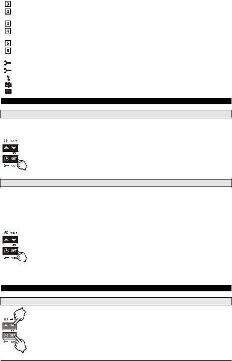
3.1 HOW TO SET THE KIND OF GAS
The controller has memorised the relation between temperature and pressure for some gases.
The pre-set gas is: r404.
If another gas is used, act as in the following:
1.Enter the Programming mode by pressing the Set and DOWN key for 3s.
2.Select the “Pr2” parameter. Then enter the password 3 –2 1.
3.Select the FtyP, kind of gas, parameter.
4.Press the “SET” key: the value of the parameter will start blinking.
1592001320 XC650C GB r2.2 26.08.2015 |
XC650C |
4/24 |

5.Use “UP” or “DOWN” to change the gas amount the following: . Select the gas among the following: r22= R22; r404=R404A; 507=R507; 134=134; r717= ammonia.
6.Press “SET” to store the new value and move to the following parameter.
To exit: Press SET + UP or wait 30s without pressing a key.
NOTE: the set value is stored even when the procedure is exited by waiting the time-out to expire.
3.2 HOW TO SET THE RANGE OF THE PRESSURE PROBES
If an instrument with the following part number is used: XC650C – xxxxF, it is pre-set to work with pressure probe with the following range:
Probe 1: -0.5 ÷11 bar (relative pressure); Probe 2: 0÷30 bar (relative pressure)
If the probes you’re using have a different range act as in the following:
To set the pressure range of the Probe 1 use the parameter:
PA04: Adjustment of read out corresponding to 4mA
PA20: Adjustment of read out corresponding to 20mA
Practically these parameters has to be set with the start and end scale of the probe range.
WARNING: set a value correspondent to absolute pressure. If the transducer measures relative pressure increase the range of 1 bar.
E.I. PP11 relative pressure transducer, range -0.5÷11.0 bar. PA04=0.50; PA20=12.00. PP30 relative pressure transducer, range: 0÷30bar. PA04=1.00; PA20=31.00.
How to do:
1.Enter the Programming mode by pressing the Set and DOWN key for 3s.
2.Select the “Pr2” parameter. Then enter the password 3 –2 1.
3.Select the PA04, adjustment of read out corresponding to 4mA, parameter.
4.Press the “SET” key: the value of the parameter will start blinking.
5.Set the lower value of the probe range (lower value +1 if the probe detects relative pressure).
6.Push the SET key to confirm the value. The PA20: adjustment of read out corresponding to 20mA parameter will be displayed.
7.Set the higher value of the range (higher value +1 if the probe detects relative pressure).
8.Push the SET key to confirm the value. Next parameter will be displayed.
Do the same things for the Probe 2, FA04, FA20 parameters.
3.3 HOW TO SET THE KIND OF DISPLAY: RELATIVE OR ABSOLUTE PRESSURE
After setting the probe range by means of the PA04, PA20, FA04 and FA20 parameters, it’s possible to select if the absolute or relative pressure has to be displayed.
The controller is pre-set for RELATIVE PRESSURE displaying.
If the absolute pressure has to be displayed, act as in the following:
1.Enter the Programming mode by pressing the Set and DOWN key for 3s.
2.Select the “Pr2” parameter. Then enter the password 3 –2 - 1.
1.Select by pushing the UP key the rELP parameter.
2.Push the SET to modify the value.
3.Set the AbS value and push the SET key to confirm it.
To exit: Press SET + UP or wait 30s without pressing a key.
1592001320 XC650C GB r2.2 26.08.2015 |
XC650C |
5/24 |

4. USER INTERFACE
4.1 DISPLAYING
|
UPPER DISPLAY |
LOWER DISPLAY |
|
ICONS |
1 probe |
Temperature |
Pressure |
- |
Working loads |
enabled |
|
|
- |
Measurement unit |
|
|
|
- |
Alarm or status Icons |
2 probes |
Probe 1 |
Probe 2 |
- |
Working loads |
enabled |
|
|
- |
Measurement unit |
|
|
|
- |
Alarm or status Icons |
4.2 KEYBOARD
SET To see or modify the set point. in programming mode it selects a parameter or confirm an operation. Alarm menu: By holding it pressed for 3s, the current alarm is erased.
o (UP) To enter the Alarm menu.
In programming mode: it browses the parameter codes or increases the displayed value. With Hot key inserted: it starts the Hot key programming procedure.
n (DOWN) In programming mode: it browses the parameter codes or decreases the displayed value.
Manual restart of loads: By holding it pressed for 3s, it switches on again loads previous locked by a safety digital input alarm.
eCLOCK To display the loads running hours.
By holding it pressed for 3s the Maintaining menu is entered.
KEY COMBINATIONS
o + n To lock and unlock the keyboard. SET + n To enter the programming mode. SET + o To exit the programming mode.
4.3 ICONS
|
LED |
FUNCTION |
MEANING |
|
|
|
|
ON |
Celsius degrees |
|
|
|
|
ON |
Fahrenheit degrees |
|
|
|
bar |
ON |
bar displaying |
|
|
|
PSI |
ON |
PSI displaying |
|
|
|
|
ON |
Load 1 on |
|
|
|
|
|
|
|
|
|
|
Flashing |
Load 1 is waiting to start (1HZ). or digital input alarm for Load 1 (2Hz). |
|
|
|
|
|
o Load 1 in maintenance status (2Hz). |
|
|
|
|
ON |
Load 2 on |
|
|
|
|
|
|
|
|
|
|
Flashing |
Load 2 is waiting to start (1HZ). or digital input alarm for Load 2 (2Hz). |
|
|
|
|
|
o Load 2 in maintenance status (2Hz). |
|
|
|
|
|
|
|
|
|
1592001320 XC650C GB r2.2 26.08.2015 |
XC650C |
6/24 |
||
|
ON |
Load 3 on |
|
|
|
|
Flashing |
Load 3 is waiting to start (1HZ). or digital input alarm for Load 3 (2Hz). |
|
|
o Load 3 in maintenance status (2Hz). |
|
ON |
Load 4 on |
|
|
|
|
Flashing |
Load 4 is waiting to start (1HZ). or digital input alarm for Load 4 (2Hz). |
|
|
o Load 4 in maintenance status (2Hz). |
|
ON |
Load 5 on |
|
|
|
|
Flashing |
Load 5 is waiting to start (1HZ). or digital input alarm for Load 5 (2Hz). |
|
|
o Load 5 in maintenance status (2Hz). |
|
ON |
The Maintenance menu has been entered |
|
|
|
|
Flashing |
One or more loads have been placed in maintenance status |
|
|
|
|
ON |
Alarm is happening |
|
|
|
|
ON |
All the stored alarms have been seen. |
|
Flashing |
A new alarm has happened |
5. HOW TO SEE AND MODIFY THE SET POINT(S)
5.1 HOW TO SEE THE SET POINT OF COMPRESSORS AND/OR FANS
If the controller is managing both compressors and fans, both the set points are displayed in sequence, otherwise only the set point of the enabled section will be displayed.
1) Push and release the SET key;
2) The Lower display will show the “SEtC” label, will the Upper display will show its value. 3) To see the fan set point push again the SET key.
1) The Lower display will show the “SEtF” label, will the Upper display will show the fan set point.
To exit: push the SET key or wait for 30 without pressing any keys.
5.2 HOW TO MODIFY THE SET POINT OF COMPRESSORS AND/OR FANS
WARNING: before setting the target set points for the first time, check and, if necessary, modify the type of freon (par. FtyP) and the default unit of measurement (par. dEU) for compressors and fans
PROCEDURE
1.Set the kind of freon by means of the FtyP parameter (see 3.1 How to set the kind of gas)
2.Set the measurement unit (dEU par.).
3.Check and if necessary modify the set point limits (LSE and HSE par.).
1. Push the SET key for more than 2 seconds;
2. The Lower display will show the “SEtC” label, will the Upper display will show its value flashing. 3. To change the Set value push the o or n within 30s.
4. To memorise the new value and pass to the fan set point push the SET key.
5. The Lower display will show the “SEtF” label, will the Upper display will show the fan set point flashing.
6.To change its value push the o or n within 30s.
To exit: push the SET key or wait for 30 without pressing any keys.
6. PARAMETERS PROGRAMMING
6.1 HOW TO ENTER THE “PR1” PARAMETER LIST
To enter the “Pr1” parameter list, user accessible, operate as follows:
1. Hold pressed the SET and DOWN key for 3s.
2. The controller displays the name of the parameter in the Lower display, its value on the Upper display. 3. Press the “SET” key: the value of the parameter will start blinking.
4. Use “UP” or “DOWN” to change the value.
5. Press “SET” to store the new value and move to the following parameter.
1592001320 XC650C GB r2.2 26.08.2015 |
XC650C |
7/24 |
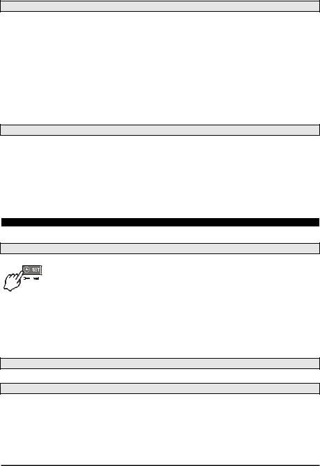
To exit: Press SET + UP or wait 30s without pressing a key.
NOTE: the set value is stored even when the procedure is exited by waiting the time-out to expire.
6.2 HOW TO ENTER IN PARAMETERS LIST “PR2”
The “Pr2” parameter list is protected by a security code (Password).
SECURITY CODE is 321
To access parameters in “Pr2”:
1.Enter the “Pr1” level.
2.Select “Pr2” parameter and press the “SET” key.
3.The flashing value “0 --” is displayed.
4.Use o or n to input the security code and confirm the figure by pressing “SET” key.
5.Repeat operations 2 and 3 for the other digits.
NOTE: each parameter in “Pr2” can be removed or put into “Pr1” (user level) by pressing “SET” + n. When a parameter is present also in “Pr1” decimal point of the lower display is on.
6.3 HOW TO CHANGE PARAMETER VALUES
1.Enter the Programming mode.
2.Select the required parameter with o or n.
3.Press the “SET” key the value start blinking.
4.Use o or n to change its value.
5.Press “SET” to store the new value and move to the following parameter.
To exit: Press SET + UP or wait 15s without pressing a key.
NOTE: the new programming is stored even when the procedure is exited by waiting the time-out.
7. HOW TO DISABLED AN OUTPUT
To disabled an output during a maintenance session means to exclude the output from the regulation.
7.1 HOW TO DISABLED AN OUTPUT DURING A MAINTENANCE SESSION.
1. Push the CLOCK key for 3 sec.
2. The LED’s of the first output is switched on, the Lower display shows the “StA” label, while the Upper display shows the “On” label if the first output is enabled, or the “oFF” label if the output is disabled for a maintenance section. With compressor with more steps all the
LED’s linked to the compressor and the valves are switched on.
3.Select the output by pressing the UP or DOWN key.
4.To modify the status of the output: push the SET key, the status of the output starts flashing, then push the UP or DOWN to pass from “On” to “OFF” and viceversa.
5.Push the SET key to confirm the status and pass to the next output.
To exit: push the CLOCK key or wait 30 sec.
7.2 OUTPUT DISABLED SIGNALLING.
If an output is disabled, its led will blink (2 Hz).
7.3 REGULATION WITH SOME OUTPUTS DISABLED.
If some outputs are disabled they don’t take part to the regulation, so the regulation goes on with the other outputs.
1592001320 XC650C GB r2.2 26.08.2015 |
XC650C |
8/24 |
 Loading...