


EC2-391 Display Case and Coldroom Controller
Operating Instructions
GB
Note: This document contains short form instructions for experienced users. Use last column in List of Parameters to document your individual settings. More detailed information can be found in the User Manual.
The EC2-391 is a dedicated refrigeration controller with superheat and a driver for an Alco Controls Electric Control Valve EX2. In addition the EC2-391 controls air temperature and manages defrost and fan(s).
Two ECN-Pxx pipe temperature sensors (1) and (2) measure suction gas temperatures at the evaporator inlet / outlet and feed the signals into the superheat control loop. The superheat controller output modulates the opening of the EX2 pulse width modulated Electrical Control Valve (6) thus optimising the refrigerant mass flow through the evaporator. The air temperature sensors (3) and (4) measure air-in and out temperature of the evaporator and feed signals into the air temperature thermostat. The ECN-Fxx fin sensor (5) is used for defrost termination. The controller has 3 relay outputs to control the defrost heater (9), the evaporator fan (8) and an optional output (7). Please consult the technical data (right) for input and output ratings.
In case of power loss, due to the positive shut-off characteristics of the EX2 Electrical Control Valves, a liquid line solenoid valve is not needed to prevent flooding of the compressor.
!Safety instructions:
•Read installation instructions thoroughly. Failure to comply can result in device failure, system damage or personal injury.
•The product is intended for use by persons having the appropriate knowledge and skills.
•Ensure electrical ratings per technical data are not exceeded.
•Disconnect all voltages from system before installation.
•Keep temperatures within nominal limits.
•Comply with local electrical regulations when wiring
Technical Data
EC2 Series Controller
Power supply |
|
24VAC ±10%; 50/60Hz; Class II |
Power consumption |
|
20VA max including EX2 |
Communication |
|
LonWorks® Interface, FTT10, RJ45 connector |
Plug-in connector size |
|
Removable screw terminals |
|
|
wire size 0.14 … 1.5mm2 |
Temperature |
|
|
storage |
|
-20 … +65°C |
operating |
|
0 … +60°C |
Humidity |
|
0…80% r.h. non condensing |
Protection class |
|
IP65 (front protection with gasket) |
Pressure transmitter input |
24VDC, 4...20mA |
|
Output relays |
(3) |
SPDT contacts, AgCdO |
|
|
Inductive (AC15) 250V/2A |
|
|
Resistive (AC1) 250V/8A; 12A total return current |
Triac output for EX2 |
|
24V AC, 0.1 … 1A |
Electrical Control Valve |
|
|
Coil (ASC 24V only) |
|
|
Marking |
|
|
|
|
|
Mounting
The EC2-391 can be mounted in panels with a 71 x 29 mm cutout. See dimensional drawing below for space requirements including rear connectors.
Push controller into panel cutout.(1)
Make sure that mounting lugs are flush with outside of controller housing
Insert allen key into front panel holes and turn clockwise. Mounting lugs will turn and gradually move towards panel (2)
Turn allen key until mounting lug barely touches panel. Then move other mounting lug to the same position (3)
Tighten both sides very carefully until controller is secured. Do not over tighten as mounting lugs will break easily.
Electrical Installation
Refer to the electrical wiring diagram (below) for electrical connections. A copy of this diagram is labeled on the controller. Use connection wires/cables suitable for 90°C operation (EN 60730-1).
EC2 analog inputs are for dedicated sensors only and should not be connected to any other devices. Important: Keep controller and sensor wiring well separated from mains wiring. Minimum recommended distance 30mm.
Warning: Use a class II category transformer for 24VAC power supply (EN 60742). Do not ground the 24VAC lines. We recommend to use one transformer per EC2 controller and to use separate transformers for 3rd party controllers, to avoid possible interference or grounding problems in the power supply. Connecting any EC2 inputs to mains voltage will permanently damage the EC2.
EC2-391_65136_EN_R01.doc |
Replacement for 00 |
1 / 4 |
PCN: 865 022 |
21.09.2007 |
EC2-391 Display Case and Coldroom Controller
Operating Instructions
GB
Recommended Sensor Positions in Detail:
(1) ECN-Pxx coil-in temperature sensor: Position on the first return bend of the evaporator.
(2) ECN-Pxx coil-out temperature sensor: Position directly after the evaporator on the common suction line.
(3)ECN-Pxx air-in temperature sensor: Position in the middle of the cabinet as high as possible.
(4)ECN-Pxx air-out temperature sensor: Position asymmetric closer to the expansion valve as high as possible.
(5)ECN-Fxx fin temperature sensor: Position on the evaporator, asymmetric closer to the expansion valve.
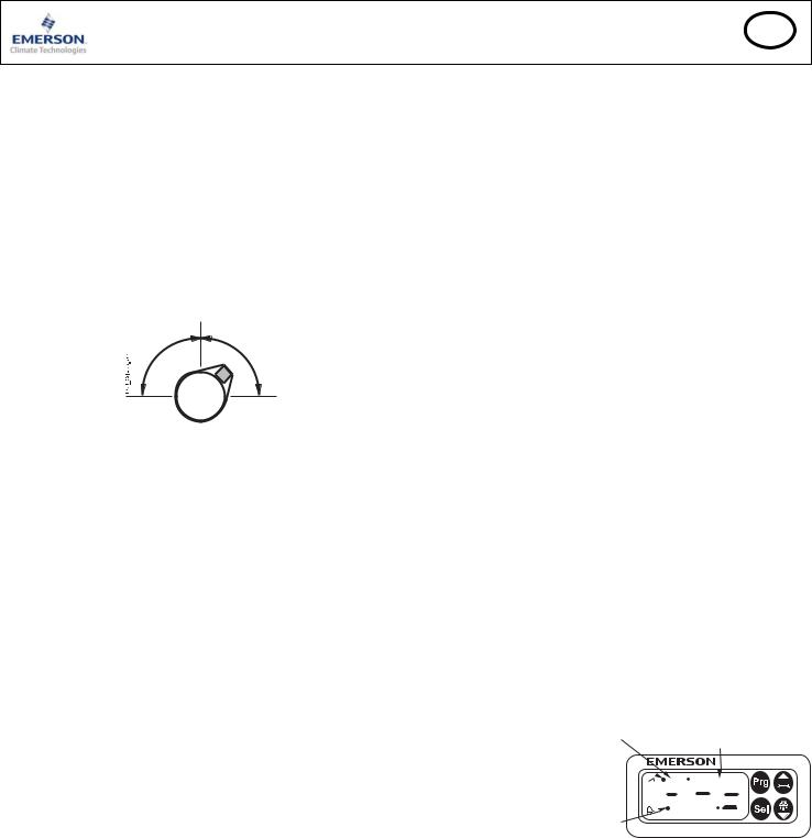
Recommendations for mounting the pipe sensor: Insure proper thermal contact by using a metallic pipe clamp or temperature resistant plastic straps. Do not use standard plastic tie wraps (as used for electrical wiring) as they may become loose over time, which could result in faulty temperature measurements and poor superheat control performance. It is recommended to insulate the pipe temperature sensor with ARMAFLEX™ or equivalent. The recommended position of the pipe sensors is between 9 and 3 o’clock as shown in the picture.
Both air temperature sensors should be mounted on spacers in the air duct so that there is airflow around.
Caution: The sensor cables can be extended if necessary. The connection must be protected against water and dust.
The evaporator outlet temperature sensor should be mounted on the common suction header of the evaporator.
A calibration correction can be made using the parameter u1 (see procedure below).
Setup and Parameter Modification Using the Keypad
For convenience, an infrared receiver for the optional IR remote control unit is build-in, enabling quick and easy modification of the system parameters when a computer interface is not available.
Alternatively, the parameters can be accessed via the 4-button keypad. The configuration parameters are protected by a numerical password. The default password is “12”. To select the parameter configuration:
•Press the PRG button for more than 5 seconds, a flashing “0” is displayed
•Press  or
or  until “12” is displayed (password)
•Press SEL to confirm password
The first modifiable parameter code is displayed (/1).
To modify parameters see Parameters modification below.
Parameter Modification: Procedure
•Press  or
or  to show the code of the parameter that has to be changed;
•Press SEL to display the selected parameter value;
•Press  or
or  to increase or decrease the value;
•Press SEL to temporarily confirm the new value and display its code;
•Repeat the procedure from the beginning "press  or
or  to show..."
To exit and save the new settings:
•Press PRG to confirm the new values and exit the parameters modification procedure.
To exit without modifying any parameter:
•Do not press any button for at least 60 seconds (TIME OUT).
•Press “ESC” on IR remote control.
EC2-391_65136_EN_R01.doc |
Replacement for 00 |
Defrost Activation:
A defrost cycle can be activated locally from the keypad:
•Press the  button for more than 5 seconds, a flashing “0” is displayed
•Press  or
or  until “12” is displayed (password)
•Press SEL to confirm password
The defrost cycle is activated.
Special Functions:
The Special Functions can be activated by:
•Press  and
and  together for more than 5 seconds, a flashing “0” is displayed.
•Press  or
or  until the password is displayed (default = 12). If password was changed, select the new password.
•Press SEL to confirm password, a “0” is displayed and the Special Function mode is activated.
•Press  or
or  to select the function. The number of special functions is dynamic and controller dependent. See list below.
•Press SEL to activate the function without leaving the special function mode.
•Press PRG to activate the function and leave the special function mode.
Most of the Special Functions work in a toggle mode, the first call activates the function, and the second call deactivates the function.
The indication of the function can only be displayed after exiting the special function mode.
•0: Display test function
•1: Clear alarm messages
•2: Cleaning mode. The cleaning mode is effectively a manual defrost with the option of the fans on/off. The cleaning mode should not be used in order to isolate the application for maintenance purposes.
•3: Fans only
•4: Set the electronic control valve to 100% open
•5: Resets all parameters to the factory default setting. The controller will indicate “oF” during the reset and the valve will close.
Display of Data:
The data to be shown on the display can be selected by the user. In case of an alarm, the alarm code is displayed alternately with the selected data. The user can inhibit the alarm code. Press the SEL button to scroll through all possible displayable data.
The display will show for one second the numerical identifier of the data and then the selected data. After two minutes the display will return to the by parameter /1 selected data.
It is possible to temporarily display the values of the different sensors. This is a useful feature when initially setting-up the system without the aid of the WebPages. Press the SEL sequentially. The value displayed on the screen corresponds to the number corresponding to the /1 parameter. Action only valid when parameter H2 = 3.
IR LED
Logical status of lighting relay
LON service LED 
Logical status of fan relay 


 Logical status of defrost heater relay


Alarm condition
2 / 4 |
PCN: 865 022 |
21.09.2007 |
 Loading...