


READ AND SAVE THESE INSTRUCTIONS
LOFT™
60” Damp Location
Ceiling Fan |
Manual |
Model |
|
CF765BQ00
CF765BS00
CF765WW00
Black
Steel
White
Net |
.7 Lbs. |
|
|
|
|
|
|
Part No. F40BP73780000 |
Form No. BP7378 |
|
U.L. Model No.: CF765 |
! WARNING
WARNING:To avoid fire, shock, and serious personal injury, follow these instructions.
Safety Instructions
1.Read your owner’s manual carefully and keep it for future reference.
2.Before servicing or cleaning unit, switch power off at service panel and lock service panel disconnecting means to prevent power from being switched on accidentally. When the service disconnecting means cannot be locked, securely fasten a warning device, such as a tag, to the service panel.
3.Be careful of the fan and blades when cleaning, painting, or working near the fan. Always turn off the power to the ceiling fan before servicing.
4.Do not put anything into the fan blades while they are turning.
5.Do not operate reversing switch until fan blades have come to a complete stop.
Additional Safety Instructions for Installation
1.To avoid possible shock, be sure electricity is turned off at the fuse box before wiring, and do not operate fan without blades.
2.All wiring must be in accordance with the National Electrical Codes “ANSI/NFPA 70-1999” and Local Electrical Codes. Use the National Electrical Code if Local Codes do not exist. The ceiling fan must be grounded as a precaution against possible electrical shock. Electrical installation should be made or approved by a licensed electrician.
3.The outlet box and joist must be securely mounted and capable of reliably supporting at least 50 pounds. Use only U.L. outlet boxes listed as “Acceptable for Fan Support”, and use the mounting screws provided with the outlet box. Most outlet boxes commonly used for support of light fixtures are not acceptable for fan support and may need to be replaced. Consult a qualified electrician if in doubt.
4.The downrod furnished with the fan proves the minimum recommended floor to fan blade clearance for an 8 foot ceiling.
5.The fan must be mounted with the fan blades at least 7 feet from the floor to prevent accidental contact with the fan blades.
6.Follow the recommended instructions for the proper method of wiring your ceiling fan. If you do not know enough about electrical wiring, have your fan installed by a licensed electrician.
NOTE: This fan is suitable for use with solid-state speed controls.
WARNING: To reduce the risk of fire or electric shock, this fan should only be used with fan speed control SW46, manufactured by Rhine Electric Co., Ltd.
WARNING: To avoid fire, shock or injury, do not use an Emerson or any other brand of control not specifically approved for this fan.
WARNING: This product is designed to use only those parts supplied with this product and/or any accessories designated specifically for use with this product by Emerson Electric Co. Substitution of parts or accessories not designated for use with this product by Emerson Electric Co. could result in personal injury or property damage.
WARNING: To reduce the risk of personal injury, do not bend the blade flange when installing the blade flanges, balancing the blades or cleaning the fan. Do not insert foreign objects in between rotating fan blades.
WARNING: To reduce the risk of electrical shock, this fan must be installed with an isolating wall control/switch.
THIS FAN IS SUITABLE FOR DAMP LOCATIONS SUCH AS COVERED PORCHES, COVERED PATIOS, AND COVERED DECKS. . .
ANYWHERE THERE IS A ROOF OVERHEAD.
DATE CODE:
The date code of this fan may be found on the box, stamped in ink on a white label. You should record this data above and keep it in a safe place for future use.
2 |
U.L. Model No.: CF765 |
This Manual Is Designed to Make it as Easy as Possible for You to Assemble, Install, Operate and Maintain Your Ceiling Fan
Tools Needed for Assembly
One Phillips head screwdriver One stepladder
One wire stripper
MATERIALS
Wiring, outlet box and box connectors must be of type required by the local code. The minimum wire would be a 3-conductor (2-wire with ground) of the following sizes:
Installed Wire Length |
Wire Size A.W.G. |
Up to 50 ft. |
14 |
50-100 ft. |
12 |
!WARNING
Before assembling your ceiling fan, refer to section on proper method of wiring your fan (page 6). If you feel you do not have enough wiring knowledge or experience, have your fan installed by a licensed electrician.
Unpacking Instructions
For your convenience, check-off boxes are provided next to each step. As each step is completed, place a check mark in the box. This will insure that all steps have been completed and will be helpful in finding your place should you be interrupted.
!WARNING
Do not install or use fan if any part is damaged or missing. Call Toll-Free:
1-800-654-3545
!WARNING
This product is designed to use only those parts supplied with this product and/or any accessories designated specifically for use with this product by Emerson Electric Co. Substitution of parts or accessories not designated for use with this product by Emerson Electric Co. could result in personal injury or property damage.
7.Four M5 external tooth lockwashers
8.Two 8-32 knurled nuts
9.Two #8 external tooth lockwashers 10. Two 8-32 x 1-1/4” threaded studs
NOTE: Intermixing blades between fans can cause excessive wobble. Keep blades in original sets of three.
1.Unpack the items carefully to avoid damage to any of the components.
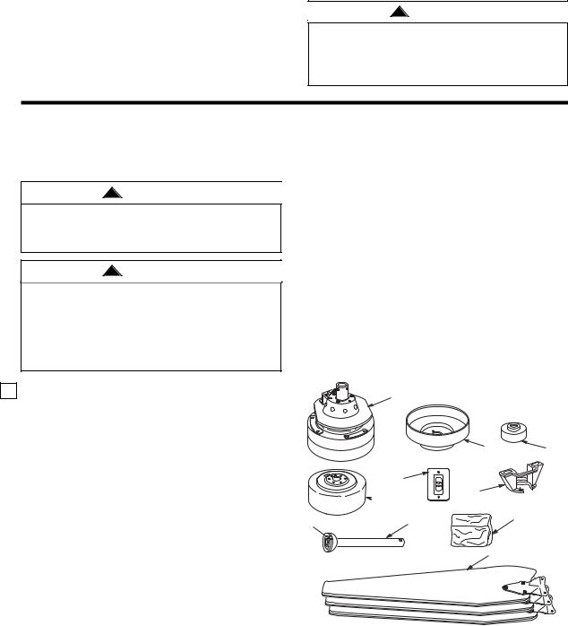
Check to see that you have received the following parts:
NOTE: If you are uncertain of part description, refer to the exploded view illustration.
a.Fan motor assembly
b.One ceiling cover
c.One coupling cover
d.One motor cover
e.Three fan blade assemblies
f.One hanger bracket
g.One hanger ball/downrod assembly
h.One SW46 wall control
i.One loose parts bag, containing:
1.One clevis pin
2.One hairpin clip
3.Three wire connectors
4.Seven M6 x 12mm pan head blade screws
5.Seven blade M6 lockwashers
6.Four M5 x 10mm pan head screws
a
h
 d
d
g
4
3
2
1
0
b |
c |
f
i
e
3 |
U.L. Model No.: CF765 |

Electrical Requirements
Your new ceiling fan will require a grounded electrical supply line of 120 volts AC, 60 Hz, 15 amp circuit.
The outlet box must be securely anchored and capable of withstanding a load of at least 50 pounds.
!WARNING
To reduce the risk of fire, electric shock, or personal injury, mount fan to outlet box marked “Acceptable for Fan Support of 50 lbs. or less”, and use screws supplied with outlet box. Most outlet boxes commonly used for support of light fixtures are not acceptable for fan support and may need to be replaced. Consult a qualified electrician if in doubt.
If your fan is to replace an existing ceiling light fixture, turn electricity off at the main fuse box at this time and remove the existing light fixture.
!WARNING
Turning off wall switch is not sufficient. To avoid possible electrical shock, be sure electricity is turned off at the main fuse box before wiring. All wiring must be in accordance with National and Local codes and the ceiling fan must be properly grounded as a precaution against possible electrical shock.
Assembly Instructions
CAUTION: The blade assemblies must be mounted on the motor assembly so that the raised lip edge is facing up (Figure 1).
1.Rotate the motor hub so the notched area is above the screw hole in the motor hub. Install one blade assembly on the top of the motor assembly using two M6 x 12mm pan head screws and two M6 lockwashers (supplied) (Figure 1). Repeat this procedure for the remaining two blade assemblies.
REVERSING SWITCH
M6 x 12mm PAN HEAD SCREW
M6 LOCKWASHER
BLADE
ASSEMBLY
FLAT AREA OF
MOTOR HUB 
REMOVE SETSCREW (2)
MOTOR ASSEMBLY 
2.Remove the two setscrews from the top of the motor coupler (Figure 1). Retain the setscrews for future use.
3.Route the two 80” motor leads through the center hole in the motor cover. Place the motor cover over the motor by aligning the reversing switch hole in the cover over the reversing switch as shown in Figure 2. Secure by installing three M5 x 10mm pan head screws and three M5 external tooth lockwashers (supplied) (Figure 2).
M5 x 10mm PAN HEAD
SCREW (3)
M5 EXTERNAL TOOTH
LOCKWASHER (3)
MOTOR COVER
Figure 2
4.Remove the hanger ball by loosening the setscrew in the hanger ball until the ball falls freely down the downrod (Figure 3). Remove the pin from the downrod, then remove the hanger ball. Retain the pin and hanger ball for reinstallation in Step 9.
PIN
HANGER
BALL
DOWNROD
SETSCREW
Figure 3
5.Separate, untwist and unkink the two motor leads, then route them through the hanger ball/downrod assembly and seat the downrod in the motor coupler (Figure 4).
6.Align the clevis pin holes in the downrod with the holes in the motor coupler. Install the clevis pin and secure with the hairpin clip (Figure 4). The clevis pin must go through the holes in the motor coupler It is critical that the clevis pin in the motor coupler is properly installed and the setscrews securely tightened. Failure to verify that the pin and setscrews are properly installed could result in the fan falling.
7.Install two setscrews (previously removed in Step 2) in the motor coupler (Figure 4). While pulling up on the hanger ball, securely tighten both setscrews.
Figure 1 |
4 |
U.L. Model No.: CF765 |
 Loading...