


CF711PB01
Part No. F40BP72580004 Form No. BP7258-4
U.L. Model No.: 42-ANT/52-ANT
READ AND SAVE THESE INSTRUCTIONS
BUILDER PLUS Series
Ceiling Fan Owner's Manual
Net Weight: 19.8 Lbs.Net Weight: 15.0 Lbs.
50” Model No.
CF711AB01 CF711PB01
CF711AW01 CF711WB01
CF711BS01 CF711WW01
CF711CK01
42” Model No.
CF710AB01
CF710AW01
CF710BS01
CF710PB01
CF710WW01
CF711 shown
WARNING: To avoid fire, shock, and serious personal injury, follow these instructions.
Safety Instructions
1. Read your owner’s manual carefully and keep it for future reference.
2. Before servicing or cleaning unit, switch power off at service panel and lock service panel disconnecting
means to prevent power from being switched on accidentally. When the service disconnecting means cannot
be locked, securely fasten a warning device, such as a tag, to the service panel.
3. Be careful of the fan and blades when cleaning, painting, or working near the fan. Always turn off the power to
the ceiling fan before servicing.
4. Do not put anything into the fan blades while they are turning.
5. Do not operate reversing switch until fan blades have come to a complete stop.
Additional Safety Instructions for Installation
1. To avoid possible shock, be sure electricity is turned off at the fuse box before wiring, and do not operate fan
without blades.
2. All wiring must be in accordance with the National Electrical Code, “ANSI/NFPA 70-1999” and Local Electrical
Codes. Use the National Electrical Code if Local Codes do not exist. The ceiling fan must be grounded as a
precaution against possible electrical shock. Electrical installation should be made or approved by a licensed
electrician.
3. The outlet box and joist must be securely mounted and capable of reliably supporting at least 50 pounds. Use
only U.L. outlet boxes listed as “Acceptable for Fan Support”, and use the mounting screws provided with the
outlet box. Most outlet boxes commonly used for support of light fixtures are not acceptable for fan support
and may need to be replaced. Consult a qualified electrician if in doubt.
4. The downrod furnished with the fan proves the minimum recommended floor to fan blade clearance for an
8 foot ceiling.
5. The fan must be mounted with the fan blades at least 7 feet from the floor to prevent accidental contact with the
fan blades.
6. Follow the recommended instructions for the proper method of wiring your ceiling fan. If you do not know
enough about electrical wiring, have your fan installed by a licensed electrician.
NOTE: The CF711 fan is suitable for use with solid-state speed controls.
WARNING: To avoid fire, shock or injury, do not use an Emerson or any other brand of control not specifically
approved for this fan.
WARNING: This product is designed to use only those parts supplied with this product and/or any accessories
designated specifically for use this product by Emerson Electric Co. could result in personal injury or property
damage.
WARNING: To Reduce the risk of personal injury, do not bend the blade flange when installing the blade flanges,
balancing the blades or cleaning the fan. Do not insert foreign objects in between rotating fan blades.
WARNING: To reduce the risk of electrical shock, this fan must be installed with an isolating wall control/switch.
2
WARNING
!
DATE CODE:
The date code of this fan may be found on
the box, stamped in ink on a white label.
You should record this data above and keep
it in a safe place for future use.
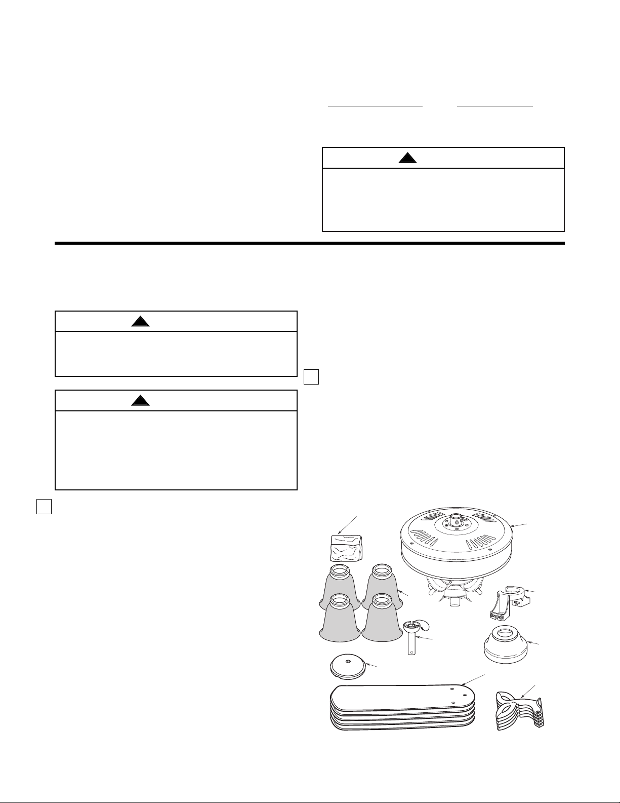
1. Check to see that you have received the following
parts:
NOTE: If you are uncertain of part description,
refer to exploded view illustration.
a. Fan motor assembly
b. Five fan blades
c. One ceiling cover
d. Five blade flanges
e. One hanger ball/downrod assembly
f. One hanger bracket
g. One switch housing cover
h. Glass shades (3 or 4)
i. One loose parts bag containing:
1. Sixteen M5 x 6 washer
head blade screws
2. One rubber gasket
3. Two wood pendants
4. Two couplings
5. Three wire connectors
6. One clevis pin
7. One hairpin clip
8. One Phillips round
head flange screw
This Manual Is Designed to Make it as Easy as Possible for You to Assemble,
Install, Operate and Maintain Your Ceiling Fan
T ools Needed for Assembly
One Phillips head screwdriver One stepladder
One 1/4” blade screwdriver One wire stripper
Three wire connectors (supplied).
Four 60-watt (max.) intermediate base bulbs (CF711)
Three 60-watt (max.) intermediate base bulbs
(CF710)
MA TERIALS
Wiring outlet box and box connectors must be of type
required by the local code. The minimum wire would
be a 3-conductor (2-wire with ground) of the following
size:
3
Installed Wire Length Wire Size A.W.G.
Up to 50 ft. 14
50-100 ft. 12
Unpacking Instructions
For your convenience, check-off boxes are provided next to each step. As each step is completed, place a
check mark in the box. This will insure that all steps have been completed and will be helpful in finding
your place should you be interrupted.
Before assembling your ceiling fan, refer to section on
proper method of wiring your fan (page 6). If you feel
you do not have enough wiring knowledge or
experience, have your fan installed by a licensed
electrician.
Do not install or use fan if any part is damaged or
missing. Call Toll-Free:
1-800-654-3545
This product is designed to use only those parts
supplied with this product and/or any accessories
designated specifically for use with this product by
Emerson Electric Co. Substitution of parts or
accessories not designated for use with this product
by Emerson Electric Co. could result in personal
injury or property damage.
NOTE: Place the parts from the loose parts bags
in a small container to keep them from being lost.
If any parts are missing, contact your local
retailer or catalog outlet for replacement before
proceeding.
2. Remove the fan housing assembly from the
protective plastic bag. Turn the upper styrofoam
pad over and carefully place the fan motor
assembly into the recess in the pad with the top of
the motor facing up.
LOOSE
PARTS
BAG
FAN
BLADES
SWITCH HOUSING
COVER
BLADE
FLANGES
GLASS
SHADES
(3 or 4)
HANGER
BRACKET
CEILING
COVER
HANGER BALL/
DOWNROD
ASSEMBLY
FAN MOTOR
ASSEMBLY
WARNING
!
WARNING
!
WARNING
!
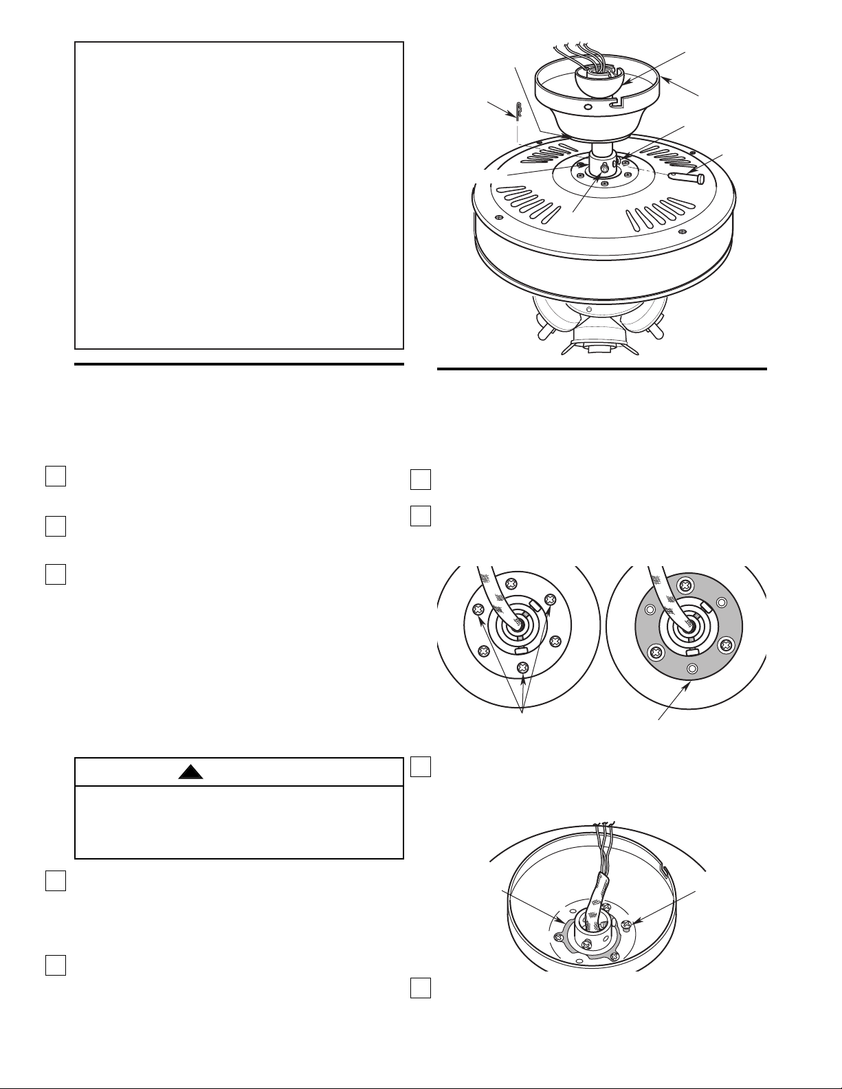
Installing The Hanger
Ball/Downrod Assembly
(For Standard Mounting)
1. Pass the 42” motor leads through the opening in
the ceiling cover. Be sure the cover is oriented
correctly.
2. Separate, untwist and unkink the three motor
leads. Route the motor leads through the hanger
ball/downrod assembly.
3. Loosen the two setscrews in the motor coupling.
Align the clevis pin holes in the downrod with the
holes in the motor coupling. Install the clevis pin
and secure with the hairpin clip (Figure 1). The
clevis pin must go through the holes in the motor
coupling and the holes in the downrod. Be sure to
push the straight leg of the hairpin clip through the
hole near the end of the clevis pin until the curved
portion of the hairpin clip snaps around the clevis
pin. The hairpin clip must be properly installed to
prevent the clevis pin from working loose. Pull on
the hanger ball to make sure the clevis pin is
properly installed.
4. While pulling up on the hanger ball, securely
tighten the two setscrews in the motor coupling
(Figure 1).
NOTE: The setscrews must be properly installed
as described above, or fan wobble could result.
5.The fan comes with blue, black and white leads that
are 42” long. Measure up approximately
6 to 9-inches above top of hanger ball/downrod
assembly. Cut off excess leads and strip back
insulation 1/2-inch from end of leads.
4
HANGER
BALL/DOWNROD
ASSEMBLY
CEILING
COVER
SETSCREW
CLEVIS
PIN
HAIRPIN
CLIP
DECORATIVE
CAP
SETSCREW
MOTOR COUPLING
Figure 1
IMPORTANT
Your ceiling fan is designed to be installed
either in the standard manner, or in the
close-to-the-ceiling manner. Using the
standard method, the hanger ball/downrod
assembly will suspend the fan several inches
below the ceiling cover. Using the
close-to-the-ceiling method, the ceiling cover
installs directly on the fan motor housing,
thus mounting the fan 3-1/2 inches closer to
the ceiling than the standard method. In no
case should the fan blades be lower than
seven feet above the floor. Depending on
your desired mounting method, proceed to
“INSTALLING HANGER BALL/DOWNROD
ASSEMBLY” for standard mounting, or to
“INSTALLING CEILING COVER ON FAN
MOTOR HOUSING” for close-to-the-ceiling
mounting.
It is critical that the clevis pin in the motor coupling
is properly installed and the setscrews securely
tightened. Failure to verify that the pin and setscrews
are properly installed could result in the fan falling.
WARNING
!
Installing The Ceiling Cover
On The Fan Motor Housing
(For Close-to-the-Ceiling Mounting)
1. Remove and retain three screws from the top of
the motor housing (Figure 2A).
2. Position the rubber gasket (supplied in parts bag)
on the motor housing (small holes in gasket
centered over the screw holes in the housing)
(Figure 2B).
3. Gently pry the decorative cap (Figure 1) from the
ceiling cover. Align the holes in the ceiling cover
with the holes in the motor housing and secure
using the three screws (Figure 3).
4. The fan comes with blue, black and white leads
that are 42” long. Measure up approximately 6 to
9-inches above the motor coupling. Cut off excess
leads and strip back insulation 1/2-inch from ends
of leads.
REMOVE SCREWS (3)
INSTALL GASKET
Figure 2A
Figure 2B
SCREW (3)
RUBBER
GASKET
Figure 3
 Loading...