


BP7305 Westfield 6/30/06 12:10 AM Page 1
READ AND SAVE THESE INSTRUCTIONS
WESTFIELD™ |
|
Wet Location |
|
52” Ceiling Fan |
Net Weight: 24.7 Lbs. |
Owner's Manual |
Model No.
CF680BQ00 CF680ORB00 CF680WB00
LIMITED WARRANTY
What The Warranty Covers:
This warranty covers the motor and the other components and accessories of your Emerson ceiling fan against all defects in workmanship and materials. You must be the original purchaser or user of the product to be covered.
What The Period Of Coverage Is:
As it applies to the motor, this warranty will last for ten years from the date you purchased your ceiling fan. All other components and accessories are covered by this warranty for one year from the date you purchased your ceiling fan. ANY IMPLIED WARRANTY OF MERCHANTABILITY OR FITNESS FOR A PARTICULAR PURPOSE, MADE WITH RESPECT TO COMPONENTS AND ACCESSORIES IS ALSO LIMITED TO ONE YEAR.
What Will Emerson Electric Co. Do To Correct Problems:
Emerson Electric Co. will replace a defective Emerson Air Comfort Ceiling Fan motor, blade, component or other accessory at no charge to you. If repair of the motor or blades is not practical or possible within a reasonable time and no replacement can be provided, Emerson will refund the actual purchase price of your fan. We will ship the repaired product or replacement to you at no charge, but you are responsible for all costs or removal, reinstallation and shipping of the product to Emerson Electric Co.
How Can You Get Service:
YOU MUST HAVE PROOF OF YOUR PURCHASE OF THE CEILING FAN TO OBTAIN LIMITED WARRANTY SERVICE. KEEP YOUR RECEIPT OR OTHER PROOF OF PURCHASE. You can return the product to our factory or to your nearest authorized service center.
•To return the product to the factory, obtain a return authorization and service identification tag by writing to Air Comfort Products, Division of Emerson Co., 8100 W. Florissant Ave., St. Louis, MO 63136. Include all model numbers shown on the product with your request.
•To return the product to an authorized service center, call 1-800-654-3545 for the address of the nearest authorized service center.
You will be responsible for all insurance, freight or other transportation charges to our factory or authorized service center. Your Emerson Air Comfort Ceiling Fan should be properly packed to avoid damage in transit since we will not be responsible for any such damage.
What Is Not Covered:
The glass globes and light bulbs of your ceiling fan are not covered by this warranty. This warranty also does not cover any defects, malfunctions or failures caused by:
•Repairs by persons not authorized by Emerson Electric Co.,
•Use of parts or accessories not authorized by Emerson Electric Co.,
•Mishandling, improper installation, modifications or damage to your ceiling fan while in your possession, or
•Unreasonable use, misuse, abuse, including failing to do reasonable and necessary maintenance, and normal wear and tear. Additionally, this warranty and any implied warranty of merchantability or fitness for a particular purpose are voided when:
•The original purchaser or user ceases to own the product, or
•The fan is moved from its original point of installation.
This warranty is only valid within the 50 states of the United States and the District of Columbia. No other written or oral warranties apply, and no employee, agent, dealer or other person is authorized to give any warranties on behalf of Emerson Electric Co.
REPAIR, REPLACEMENT OR A REFUND ARE THE EXCLUSIVE REMEDIES AVAILABLE UNDER THIS WARRANTY AND EMERSON IS NOT RESPONSIBLE FOR DAMAGES OF ANY KIND, INCLUDING INCIDENTAL AND CONSEQUENTIAL DAMAGES. Incidental damages include but are not limited to such damages as loss of time and loss of use. Consequential damages include but are not limited to the cost of repairing or replacing other property which was damaged if this product does not work properly.
How State Law Relates To The Warranty:
Some states do not allow the exclusion or limitation of incidental or consequential damages so the above exclusion or limitation may not apply to you. This warranty gives you specific legal rights, and you may also have other rights which vary from state to state.
Part No. F40BP73050001 |
Form No. BP7305-1 |
|
U.L. Model No.: CF680 |
BP7305 Westfield 6/30/06 12:10 AM Page 2
!WARNING
WARNING: To avoid fire, shock, and serious personal injury, follow these instructions.
Safety Instructions
1.Read your owner’s manual carefully and keep it for future reference.
2.Before servicing or cleaning unit, switch power off at service panel and lock service panel disconnecting means to prevent power from being switched on accidentally. When the service disconnecting means cannot be locked, securely fasten a warning device, such as a tag, to the service panel.
3.Be careful of the fan and blades when cleaning, painting, or working near the fan. Always turn off the power to the ceiling fan before servicing.
4.Do not put anything into the fan blades while they are turning.
5.Do not operate reversing switch until fan blades have come to a complete stop.
Additional Safety Instructions for Installation
1.To avoid possible shock, be sure electricity is turned off at the fuse box before wiring, and do not operate fan without blades.
2.The installation is to be in accordance with the National Electrical Code, ANSI/NFPA 70-1999 and Local Codes. Use the National Electrical Code if Local Codes do not exist. The ceiling fan must be grounded as a precaution against possible electrical shock. Electrical installation should be made or approved by a licensed electrician.
3.The outlet box and joist must be securely mounted and capable of reliably supporting at least 50 pounds. Use only U.L. outlet boxes listed as “Acceptable for Fan Support”, and use the mounting screws provided with the outlet box. Most outlet boxes commonly used for support of light fixtures are not acceptable for fan support and may need to be replaced. Consult a qualified electrician if in doubt.
4.The downrod furnished with the fan provides the minimum recommended floor to fan blade clearance for an 8 foot ceiling.
5.The fan must be mounted with the fan blades at least 7 feet from the floor to prevent accidental contact with the fan blades.
6.Follow the recommended instructions for the proper method of wiring your ceiling fan. If you do not know enough about electrical wiring, have your fan installed by a licensed electrician.
NOTE: This fan is suitable for use with solid-state speed controls.
WARNING: This product is designed to use only those parts supplied with this product and/or any accessories designated specifically for use with this product by Emerson Electric Co. Substitution of parts or accessories not designated for use with this product by Emerson Electric Co. could result in personal injury or property damage.
WARNING: To reduce the risk of personal injury, do not bend the blade flange when installing the blade flanges, balancing the blades or cleaning the fan. Do not insert foreign objects in between rotating fan blades.
DATE CODE:
The date code of this fan may be found on the box, stamped in ink on a white label. You should record this data above and keep it in a safe place for future use.
2
BP7305 Westfield 6/30/06 12:10 AM Page 3
THIS FAN IS SUITABLE FOR DAMP LOCATIONS SUCH AS COVERED PORCHES, COVERED PATIOS, AND COVERED DECKS...
ANYWHERE THERE IS A ROOF OVERHEAD.
This Manual is Designed to Make it as Easy as Possible for You to Assemble, Install, Operate and Maintain Your Ceiling Fan
Tools Needed for Assembly
One Phillips head screwdriver One wire stripper
One stepladder
Five wire connector (supplied)
Four 7-watt (max.) candelabra bulbs
Materials
Wiring, outlet box and box connectors must be of type required by the local code. The minimum wire would be a 3-conductor (2-wire with ground) of the following sizes:
Installed Wire Length |
Wire Size A.W.G. |
Up to 50 ft. |
14 |
50-100 ft. |
12 |
!WARNING
Before assembling your ceiling fan, refer to section on proper method of wiring your fan (page 10). If you feel you do not have enough wiring knowledge or experience, have your fan installed by a licensed electrician.
Unpacking Instructions
For your convenience, check-off boxes are provided next to each step. As each step is completed, place a check mark in the box. This will insure that all steps have been completed and will be helpful in finding your place should you be interrupted.
!WARNING
Do not install or use fan if any part is damaged or missing. Call Toll-Free:
1-800-654-3545
!WARNING
This product is designed to use only those parts supplied with this product and/or any accessories designated specifically for use with this product by Emerson Electric Co. Substitution of parts or accessories not designated for use with this product by Emerson Electric Co. could result in personal injury or property damage.

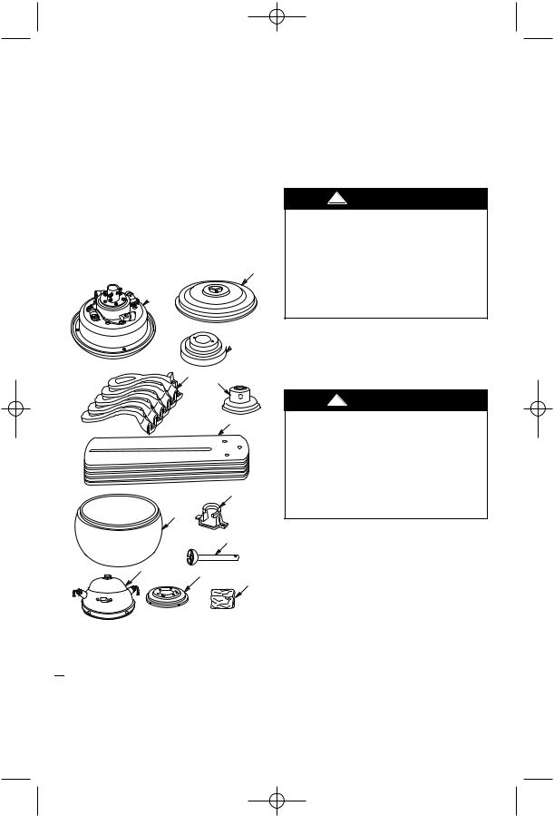
 1. Open styrofoam unit containing fan. Remove top half of styrofoam unit. Remove parts and check to see that you have received the following parts:
NOTE: If you are uncertain of part description, refer to exploded view illustration.
a.Fan motor and housing assembly
b.One upper housing
c.One ceiling cover
d.Four blade flanges
e.Four fan blades
f.One upper housing cover
g.One center glass
h.One hanger bracket
i.One hanger ball/downrod assembly
j.One switch cup assembly
k.One switch cup adapter
3
BP7305 Westfield 6/30/06 12:10 AM Page 4
l.One loose parts bag containing:
1.Two 8-32 x 1-1/4” threaded studs
2.Two knurled knobs
3.Two lockwashers
4.Five wire connectors
5.One clevis pin/hairpin clip assembly
6.Eleven 1/4-20 x 1/2” oval head screws
7.Sixteen 10-32 x .30” pan head screws
8.Sixteen #10 flat washers
9.Four 8-32 x 1/4” pan head screws
10.One pendant (large)
11.One pendant (small)
12. Two chain couplings |
B |
|
 A
A

 C
C
D
F
E
H
G
I
J
K
L
Electrical Requirements
Your new ceiling fan will require a grounded electrical supply line of 120 volts AC, 60 Hz, 15 amp circuit.
The outlet box must be securely anchored and capable of withstanding a load of at least 50 pounds.
!WARNING
To reduce the risk of fire, electric shock, or personal injury, mount fan to outlet box marked “Acceptable for Fan Support”, and use screws supplied with outlet box. Most outlet boxes commonly used for support of light fixtures are not acceptable for fan support and may need to be replaced. Consult a qualified electrician if in doubt.
If your fan is to replace an existing ceiling light fixture, turn electricity off at the main fuse or circuit breaker box at this time and remove the existing light fixture.
!WARNING
Turning off wall switch is not sufficient. To avoid possible electrical shock, be sure electricity is turned off at the main fuse or circuit breaker box before wiring. All wiring must be in accordance with National and Local codes and the ceiling fan must be properly grounded as a precaution against possible electrical shock.
NOTE: Place the parts from the loose parts bags in a small container to keep them from being lost.

 2. Remove the fan motor and housing assembly from the protective plastic bag. Place the fan assembly into the lower foam pad with the bottom of the motor facing up.
The lower foam pad serves as a holder |
|
for the fan during the first stages of |
|
assembly. |
4 |
BP7305 Westfield 6/30/06 12:10 AM Page 5
How to Assemble Your |
2. Remove and discard the four shipping |
||||||
|
Ceiling Fan |
retainers securing the motor hub in the |
|||||
|
|
|
|
motor housing. |
|
||
! |
WARNING |
NOTE: Take care not to scratch the fan |
|||||
housing when installing the blade |
|||||||
Turning off wall switch is not sufficient. |
assemblies. |
|
|
||||
To avoid possible |
electrical |
shock, be |
3. Insert an 1/4-20 x 1/2” oval head screw |
||||
sure electricity is turned off at the main |
|||||||
(supplied) into each of the two |
|||||||
fuse or circuit breaker box before wiring. |
|||||||
All wiring must be in accordance with |
recessed holes in one of the blade |
||||||
National and Local codes and the ceiling |
flanges. |
|
|
||||
fan must be properly grounded as a |
|
|
|
||||
precaution |
against |
possible |
electrical |
! |
WARNING |
||
shock. |
|
|
|
||||
|
|
|
|
To reduce the risk of personal injury, do |
|||
IMPORTANT: The side of the fan blade |
not bend the blade flanges when |
||||||
having the rib line MUST be facing |
installing the flanges, balancing the |
||||||
upward as shown in Figure 1. |
blades or cleaning the fan. Do not insert |
||||||
|
|
|
|
foreign objects between rotating fan |
|||
1. Mount the fan blades to the blade |
blades. |
|
|
||||
flanges using three 10-32 x .30” pan |
4. Position the blade flange on the motor |
||||||
head screws and three flat washers |
|||||||
(screws |
and |
washers |
supplied) |
hub so that the screws in the blades |
|||
(Figure 1). |
|
|
flange align with two threaded holes in |
||||
! |
WARNING |
the motor hub (Figure 2). Loosely |
|||||
tighten the screws at this time. Repeat |
|||||||
To reduce the risk of personal injury, do |
this procedure for the remaining four |
||||||
blade assemblies. |
|
||||||
not bend the blade flange when installing |
|
||||||
|
|
|
|||||
the blade flanges, balancing the blades or |
|
|
|
||||
cleaning the fan. Do not insert foreign |
|
|
|
||||
objects in between rotating fan blades. |
REMOVE ONE PAN HEAD |
|
|||||
|
|
|
|
|
|||
|
|
|
|
SCREW/LOCKWASHER |
MOTOR FLANGE |
||
|
|
|
|
|
|
||
|
|
10-32 x .30" |
|
|
1/4-20 x 1/2" OVAL |
||
RIB LINE (THIS SIDE |
PAN HEAD |
|
|
HEAD SCREWS (2) |
|||
OF BLADE UP) |
SCREWS (3) |
|
|
|
|||
|
|
|
FLAT |
|
|
|
|
|
|
|
WASHERS (3) |
|
|
|
|

 FAN BLADE
BLADE
FLANGE
Figure 1
BLADE
FLANGE
MOTOR HUB
Figure 2

 5. Gently snug all flange screws to the motor hub, working around the hub in a clockwise sequence. Next, securely tighten all flange screws, again working in a clockwise sequence. Failure to follow this procedure could result in fan wobble. This completes the blade installation.
5

BP7305 Westfield 6/30/06 12:10 AM Page 6

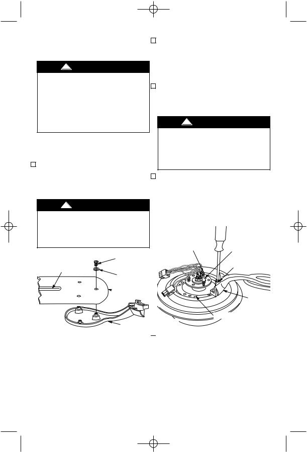
 6. Remove and retain one of the three pan head screw/lockwashers from the motor flange (Figure 2); loosen the other two pan head screws three or four turns.
7. Position the switch cup adapter on the motor flange so that the two screws mate with the two keyhole slots in the switch cup adapter (Figure 2).
NOTE: Make sure that the lockwashers are positioned between the screw head and the switch cup adapter.

 8. Turn the switch cup adapter clockwise and tighten both screws (Figure 3). Reinstall the other pan head screw/ lockwasher in the remaining hole in the switch cup adapter.
INSTALL ONE PAN HEAD
SCREW/LOCKWASHER
MOTOR FLANGE |
SWITCH CUP |
|
ADAPTER |
LARGE (9-PIN)
CONNECTORS SWITCH CUP ASSEMBLY
SMALL (2-PIN)
CONNECTORS
Figure 4

 10. Position the switch cup assembly on the switch cup adapter. Line up the three holes in the switch cup with the threaded holes in the switch cup adapter and install four 8-32 x 1/4” pan head screws (supplied) (Figure 5).
CAUTION: Before installing and tightening the screws, be sure there are no wires pinched between the switch cup adapter and switch cup assembly.
TIGHTEN TWO PAN
HEAD SCREWS
Figure 3

 9. Carefully rest the switch cup assembly on the fan blades, then engage the large (9-pin) connector of the switch cup assembly with the large motor connector (Figure 4). Connect the small (2-pin) connector of the switch cup assembly with the small motor connector. The two connectors are keyed and color-coded and must be mated correctly (color-to-color) before they can be engaged. Make sure the latches are engaged properly.
SWITCH CUP PULL CHAIN ASSEMBLY

 PENDANT


 COUPLING
SWITCH CUP ADAPTER
8-32 x 1/4" PAN HEAD SCREW (4)
Figure 5
6
 Loading...