


 BP7511-1 CF5200 Penbrooke Select Eco.qxp_ BP7511 2/8/16 12:02 PM Page 1
READ AND SAVE THESE INSTRUCTIONS |
|
44”, 54”, 60” or 72” |
TRANSITIONAL |
Fan Blades Not Included |
|
PENBROOKE SELECT ECO 

Ceiling Fan Owner's Manual
CF5200BS00Model- Numbers
Brushed Steel
CF5200ORB00 - Oil Rubbed Bronze
CF5200SW00 - Satin White
Net Weight: 21.2 Lbs.
Questions, problems, missing parts: Before returning to the store call Emerson Electric Customer Service
8 a.m. - 6 p.m., Eastern, Monday-Friday
1-800-654-3545
•Español - página 31
•Français - page 61
Part No. F40BP75110001 |
www.emersonfans.com |
Form No. BP7511-1 |
Revision: 160204 |
ETL Model No.: CF5200 |
 BP7511-1 CF5200 Penbrooke Select Eco.qxp_ BP7511 2/8/16 12:02 PM Page 2
|
|
|
|
|
|
|
|
||
|
|
|
Table of Contents |
|
|
||||
Section |
|
|
Page |
|
Section |
Page |
|||
Safety Instructions . . . . . |
. . . |
. . . . . . . . . . . . . . . . . . . |
. . . . . . . . . . . . . . . .2 |
|
10. Using Your Ceiling Fan . . . . . . . . . . . . . . . . . . . . . . . . . . . . . . . . |
. . .23 |
|||
1. Unpacking Instructions |
. . . |
. . . . . . . . . . . . . . . . . . . |
. . . . . . . . . . . . . .3-4 |
|
11. Optional AL100 Accent Light Installation . . . . . . . . . . . . . . . . . . |
. . .24 |
|||
2. Electrical Requirements . . . . . . . . . . . . . . . . . . . . . |
. . . . . . . . . . . . . . .4 |
|
12. Maintenance . . . . . . . . . . . . . . . . . . . . . . . . . . . . . . . . . . . . . . . . |
. . .25 |
|||||
3. Ceiling Fan Assembly |
. . . |
. . . . . . . . . . . . . . . . . . . . |
. . . . . . . . . . . . .5-9 |
|
13. Accessories . . . . . . . . . . . . . . . . . . . . . . . . . . . . . . . . . . . . . . . . . |
. . .25 |
|||
4. How to Hang Your Ceiling Fan . . . . . . . . . . . . . . . . |
. . . . . . . . . . .10-11 |
|
14. Energy Efficient Use of Ceiling Fan . . . . . . . . . . . . . . . . . . . . . . |
. . .25 |
|||||
5. How to Wire Your Ceiling Fan . . . . . . . . . . . . . . . . . |
. . . . . . . . . . .12-14 |
|
15. Repair Parts . . . . . . . . . . . . . . . . . . . . . . . . . . . . . . . . . . . . . . . . . |
26-27 |
|||||
6. Final Assembly . . . . . . |
. . . |
. . . . . . . . . . . . . . . . . . . . |
. . . . . . . . . . .15-16 |
|
16. Troubleshooting . . . . . . . . . . . . . . . . . . . . . . . . . . . . . . . . . . . . . . |
. . .28 |
|||
7. Wall Control Procedures . . . . . . . . . . . . . . . . . . . . . |
. . . . . . . . . . . . . .17 |
|
Ceiling Fan Limited Warranty . . . . . . . . . . . . . . . . . . . . . . . . . . . . . . |
. . .29 |
|||||
8. Wall Control Installation . . . . . . . . . . . . . . . . . . . . . . |
. . . . . . . . . . .18-21 |
|
Spanish . . . . . . . . . . . . . . . . . . . . . . . . . . . . . . . . . . . . . . . . . . . . . . . . |
. . .31 |
|||||
9. Programming the Receiver Operating Frequency |
|
|
French . . . . . . . . . . . . . . . . . . . . . . . . . . . . . . . . . . . . . . . . . . . . . . . . . |
. . .61 |
|||||
& High Speed Conditioning of Fan Control . . . . . |
. . . . . . . . . . . . . .22 |
|
|
|
|
|
|||
|
|
|
|
|
|
||||
READ AND SAVE THESE INSTRUCTIONS |
|
|
|||||||
|
|
|
|
|
|
|
|
|
|
|
|
|
Safety Instructions |
|
|
||||
|
|
|
|
|
3. The outlet box and joist must be securely mounted and |
||||
! |
|
WARNING |
|
||||||
|
|
|
capable of reliably supporting at least 50 pounds. Use |
||||||
TO REDUCE THE RISK OF FIRE, ELECTRICAL SHOCK, |
|
only U.L. outlet boxes listed as “Acceptable for Fan |
|||||||
|
Support of 22.7 kg. (50 lbs.) or less”, and use the |
||||||||
OR INJURY TO PERSONS, OBSERVE THE FOLLOWING: |
|
mounting screws provided with the outlet box. Most |
|||||||
a. Use this unit only in a manner intended by the |
|
outlet boxes commonly used for support of light fixtures |
|||||||
manufacturer. |
If you have questions, contact the |
|
are not acceptable for fan support and may need to be |
||||||
manufacturer. |
|
|
|
|
replaced. Consult a qualified electrician if in doubt. |
|
|
||
b. Before servicing or cleaning unit, switch power off at |
|
4. The downrod furnished with the fan provides the |
|||||||
service panel and lock service panel disconnecting |
|
minimum recommended floor to fan blade clearance for |
|||||||
means to prevent power from being switched on |
|
an 8 foot ceiling. |
|
|
|||||
accidentally. When the service disconnecting means |
|
5. The fan must be mounted with the fan blades at least |
|||||||
cannot be locked, securely fasten a warning device, |
|
7 feet from the floor to prevent accidental contact with |
|||||||
such as a tag, to the service panel. |
|
|
the fan blades. |
|
|
||||
|
|
|
|
|
6. Follow the recommended instructions for the proper |
||||
|
|
|
|
|
method of wiring your ceiling fan. If you do not know |
||||
|
|
|
|
|
enough about electrical wiring, have your fan installed by |
||||
1. Read your owner’s manual carefully and keep it for future |
|||||||||
|
a licensed electrician. |
|
|
||||||
reference. |
|
|
|
|
WARNING: To reduce the risk of electrical shock, this fan |
||||
2. Be careful of the fan and blades when cleaning, painting, |
|
must be installed with an isolating wall control/ switch. |
|
|
|||||
or working near the fan. Always turn off the power to the |
|
NOTE: This fan is suitable for use with solid-state speed |
|||||||
ceiling fan before servicing. |
|
|
controls. |
|
|
||||
3. Do not put anything into the fan blades while they are |
|
WARNING: This product is designed to use only those |
|||||||
turning. |
|
|
|
|
parts supplied with this product and/or any accessories |
||||
4. Do not operate reversing switch until fan blades have |
|
designated specifically for use this product by Emerson |
|||||||
come to a complete stop. |
|
|
Electric Co. Substitution of parts or accessories not |
||||||
Additional Safety Instructions for Installation |
|
designated for use with this product by Emerson could |
|||||||
|
result in personal injury or property damage. |
|
|
||||||
1. To avoid possible shock, be sure electricity is turned off |
|
WARNING: To reduce the risk of personal injury, do not |
|||||||
|
bend the blade flange when installing the blade flanges, |
||||||||
at the fuse box before wiring, and do not operate fan |
|
balancing the blades or cleaning the fan. Do not insert |
|||||||
without blades. |
|
|
|
|
foreign objects in between rotating fan blades. |
|
|
||
2. All wiring must be in accordance with the National |
|
WARNING: To avoid fire, shock or injury, do not use an |
|||||||
Electrical Code “ANSI/NFPA 70-2014” and Local |
|
||||||||
|
Emerson or any other brand of control not specifically |
||||||||
Electrical Codes. Use the National Electrical Code if |
|
||||||||
|
approved for this fan. |
|
|
||||||
Local Codes do not exist. The ceiling fan must be |
|
|
|
||||||
grounded as a precaution against possible electrical |
|
NOTE: All setscrews must be checked and re-tightened |
|||||||
shock. Electrical installation should be made or |
|
where necessary before installation. |
|
|
|||||
approved by a licensed electrician. |
|
|
|
|
|
|
|||
|
|
|
|
|
|
|
|
||
|
|
|
|
|
|
|
|
||
SERIAL NUMBER: |
|
|
|
DATE CODE: |
|
|
|
||
|
|
|
|
|
|
||||
The serial number of this fan can be found on the nameplate on top of the fan housing. The date code can be found on the carton and on top of the fan housing, stamped in ink on a white label. You should record this data above and keep it in a safe place for future use.
2 |
ETL Model No.: CF5200 |

 BP7511-1 CF5200 Penbrooke Select Eco.qxp_ BP7511 2/8/16 12:02 PM Page 3
1. Unpacking Instructions
! WARNING
Do not install or use fan if any part is damaged or missing. Call Toll1--Free:800-654-3545
! WARNING
This product is designed to use only those parts supplied with this product and/or any accessories designated specifically for use with this product by Emerson Electric Co. Substitution of parts or accessories not designated for use with this product by Emerson Electric Co. could result in personal injury or property damage.
1.1
NOTE:Check toIf seeyouthatareyouuncertainhave receivedof partthdescription,follow ng parts:refer to exploded view illustration.
HARDWARE CONTENTS
Part |
Description |
Quantity |
1 |
Threaded Studs, #8-32 x 1-1/4” |
2 |
|
|
|
2 |
Knurled Knobs, #8-32 |
2 |
|
|
|
3 |
Lockwashers, External Tooth #8 |
2 |
4 |
Wire Connectors, 12 ga. |
5 |
|
|
|
5 |
Clevis Pin |
1 |
|
|
|
6 |
Hairpin Clip |
1 |
7 |
Flat Head Screws, #6-32 x 3/8” |
4 |
8 |
Round Head Screw with Lockwasher |
|
|
#6-32 x 3/8” (Spare) |
1 |
|
|
|
9 |
Oval Head Screws, #10-32 x 5/8” |
11 |
10 |
Round Head Screws, #10-24 x 12mm |
21 |
|
|
|
11 |
Flat Washers, #10 |
21 |
12 |
Blade Balance Kit |
1 |
|
|
|
7 |
1 |
2 |
3 |
|
|
|
|
8 |
4 |
5 |
6 |
9 |
|
|
|
|
10 |
11 |
|
12 |
PACKAGE CONTENTS
Part |
Description |
Quantity |
A |
Fan Motor & Housing Assembly |
1 |
B |
Ceiling Cover |
1 |
C |
Motor Coupler Cover |
1 |
D |
Blade Flanges |
5 |
E |
Hanger Bracket |
1 |
F |
Hanger Ball / 4.5” Downrod Assembly |
1 |
G |
Switch Cup Adapter |
1 |
H |
Switch Cup Assembly |
1 |
I |
SW605 Wall Control |
1 |
|
A |
E |
|
|
|
|
|
F |
|
B |
G |
|
|
|
|
C |
H |
|
|
|
|
D |
I |
NOTE: Your ceiling fan will operate with the following Blade Select Blades (Sold Separately):
B77, B78, B79, B90, B91, B92, B97, B100, B101, B102, B103, B107, B108, B109, G44, G54, & G60.
NOTE: Place the parts from the loose parts bags in a small container to keep them from being lost. If any parts are missing, contact your local retailer or catalog outlet for replacement before proceeding.
1.2
Remove the fan motor assembly from the protective plastic bag. Place the fan assembly into the lower foam pad with the top of the motor facing up.
The lower foam pad serves as a holder for the fan during assembly.
|
emersonfans.com |
3 |
Please contact 1-800-654-3545 for further assistance |
ETL Model No.: CF5200 |
 BP7511-1 CF5200 Penbrooke Select Eco.qxp_ BP7511 2/8/16 12:02 PM Page 4
1. Unpacking Instructions (continued)
This Manual Is Designed to Make it as Easy as Possible for You to Assemble, Install, Operate and Maintain Your Ceiling Fan
|
|
|
|
Your Emerson Ceiling Fan comes supplied with a SW605 |
|
|
|
Tools Needed for Assembly |
|
||||
|
Fan Wall Control and a installed DC receiver. This system |
|
||||
|
One Phillips Head Screwdriver |
|
One Stepladder |
|
||
|
|
allows you to regulate your ceiling fan speed. |
|
|||
|
One 1/4” Blade Screwdriver |
|
One Wire Stripper |
This Emerson Ceiling Fan may be used with the following |
|
|
|
|
|
|
|
||
|
Materials |
|
accessories: SR600 Remote Control. |
|
||
|
|
|
|
|
||
|
Wiring outlet box and box connectors must be of type |
|
|
|
||
|
|
! WARNING |
|
|||
|
required by the local code. The minimum wire would be a |
|
|
|||
|
3-conductor (2-wire with ground) of following size: |
|
|
|
||
|
|
Before assembling your ceiling fan, refer to section on |
|
|||
|
|
|
|
|
|
|
|
Installed Wire Length |
Wire Size A.W.G. |
|
proper method of wiring your fan (page 12). If you feel |
|
|
|
|
|
|
|
you do not have enough wiring knowledge or experience, |
|
|
Up to 50 ft. |
|
14 |
|
have your fan installed by a licensed electrician. |
|
|
50-100 ft. |
|
12 |
|
|
|
|
|
|
|
|
|
|
|
|
|
|
|
|
|
2. Electrical Requirements
Your new ceiling fan will require a grounded electrical
supply line of 120 volts AC, 60 Hz, 15 amp circuit.
! WARNING
To reduce the risk of fire, electric shock, or personal injury, mount fan to outlet box marked “Acceptable for Fan Support of 22.7 kg. (50 lbs.) or less”, and use screws supplied with outlet box. Most outlet boxes commonly used for support of light fixtures are not acceptable for fan support and may need to be replaced. Consult a qualified electrician if in doubt.
! WARNING
Turning off wall switch is not sufficient. To avoid possible electrical shock, be sure electricity is turned off at the main fuse box before wiring. All wiring must be in accordance with National and Local codes and the ceiling fan must be properly grounded as a precaution against possible electrical shock.
The outlet box must be securely anchored and capable of withstanding a load of at least 50 pounds.
If your fan is to replace an existing ceiling light fixture, turn electricity off at the main fuse box at this time and remove the existing light fixture.
! WARNING
To avoid fire or shock, follow all wiring instructions carefully.
Any electrical work not described in these instructions should be done or approved by a licensed electrician.
Please call Emerson technical support at 1-800-654-3545 if you have any questions about installation and operation of this ceiling fan.
4 |
ETL Model No.: CF5200 |
BP7511-1 CF5200 Penbrooke Select Eco.qxp_ BP7511 2/8/16 12:02 PM Page 5 |
|
|
|
3. Ceiling Fan Assembly |
|
3.1 |
|
GREEN GROUND WIRE |
Remove the hanger ball by loosening the Phillips head set |
PIN |
|
screw in the hanger ball until the ball falls freely down the |
||
downrod (Figure 1). |
|
|
Remove the pin from the downrod, then remove the |
4.5" DOWNROD |
|
|
||
hanger ball (Figure 1). |
|
|
Retain the pin and hanger ball for reinstallation in |
|
|
Step 3.7. |
|
HANGER BALL |
|
|
|
|
|
PHILLIPS HEAD SET SCREW |
|
|
(LOOSENED) |
|
|
Figure 1 |
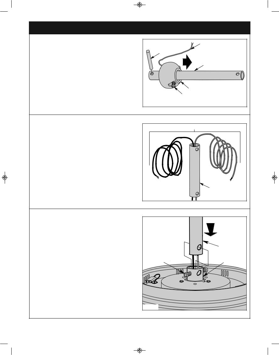
3.2
Separate, untwist and unkink the two 80” motor leads.
Route the two motor leads through the downrod (Figure 2).
TWO 80" MOTOR LEADS (UNTWISTED) |
4.5" DOWNROD |
Figure 2 |
3.3 |
|
|
Loosen the two Phillips head set screws in the motor |
|
|
coupler for installation of the downrod (Figure 3). |
|
|
Seat the 4.5” downrod in the motor coupler (Figure 3). |
|
|
Rotate and align the downrod holes with all the holes in the |
|
4.5" |
motor coupler (Figure 3). |
LOOSEN |
DOWNROD |
|
||
|
PHILLIPS HEAD |
MOTOR |
|
SET SCREWS (2) |
COUPLING |
|
Figure 3 |
|
|
|
emersonfans.com |
|
Please contact 1-800-654-3545 for further assistance |
|
5 |
ETL Model No.: CF5200 |
BP7511-1 CF5200 Penbrooke Select Eco.qxp_ BP7511 2/8/16 12:02 PM Page 6 |
|
|
|
|
|
3. Ceiling Fan Assembly |
(Continued) |
|
|
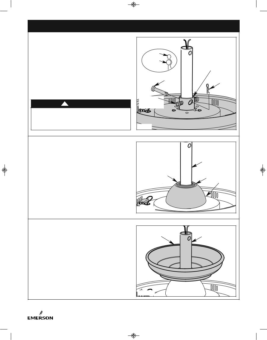
3.4 |
|
|
|
|
Align the clevis pin holes in the downrod with the holes in |
|
|
|
|
the motor coupler. |
|
HAIRPIN |
|
|
|
|
|
|
|
Install the clevis pin and secure with the hairpin clip |
CLIP |
|
|
|
CLEVIS |
|
|
||
(Figure 4). |
|
|
|
|
|
PIN |
|
|
|
The clevis pin must go through the holes in the motor |
|
|
MOTOR |
|
coupler. It is critical that the clevis pin in the motor coupler |
|
|
COUPLING |
|
|
CLEVIS |
|
||
is properly installed and securely tightened. |
|
HAIRPIN |
||
|
|
|
PIN |
|
Retighten the Phillips head screws to secure the downrod |
|
|
CLIP |
|
to the motor (Figure 4). |
WARNING |
PHILLIPS HEAD |
|
|
! |
|
|
||
It is critical that the clevis pin and setscrews in the motor |
RETIGHTEN |
|
|
|
SET SCREW (2) |
|
|
||
|
|
|
|
|
coupler are properly installed and securely tightened. |
|
|
|
|
Failure to verify that the pin and setscrews are properly |
|
|
|
|
installed could result in the fan falling. |
Figure 4 |
|
|
|
|
|
|
|
|
3.5 |
|
|
|
|
Make sure the grommet is properly installed in the coupling |
|
|
|
|
cover, then slide the coupling cover on the downrod until it |
|
|
|
|
rests on the motor housing (Figure 5). |
|
|
4.5" DOWNROD |
|
|
|
COUPLING COVER |
COUPLING |
|
|
|
GROMMET |
|
COVER |
|
|
|
|
MOTOR |
|
|
|
|
HOUSING |
|
|
Figure 5 |
|
|
3.6 |
|
|
|
|
Place the ceiling cover over the downrod (Figure 6). |
CEILING |
|
4.5" DOWNROD |
|
|
|
|
||
Be sure that the ceiling cover and the coupling cover are |
COVER |
|
|
|
|
|
|
||
both oriented correctly (Figure 6). |
|
|
|
|
|
|
Figure 6 |
|
|
6 |
ETL Model No.: CF5200 |
BP7511-1 CF5200 Penbrooke Select Eco.qxp_ BP7511 2/8/16 12:02 PM Page 7 |
|
|
|
|
3. Ceiling Fan Assembly (Continued) |
|
|
3.7 |
|
|
PIN |
Route the two motor leads through the hanger ball |
|
||
|
HANGER BALL |
||
(Figure 7). |
|
4.5" DOWNROD |
|
|
|
|
|
Reinstall the hanger ball on the downrod as follows: |
PHILLIPS HEAD |
|
|
Position the pin through the two holes in the downrod and |
|
||
SET SCREW |
|
||
align the hanger ball so the pin is captured in the groove in |
|
||
|
|
||
the top of the hanger ball (Figure 7). |
|
|
|
Pull the hanger ball up tight against the pin and securely |
|
|
|
retighten the Phillips head screw in the hanger ball |
|
|
|
(Figure 7). |
|
|
|
A loose Phillips head screw could create fan wobble. |
|
|
|
|
|
Figure 7 |
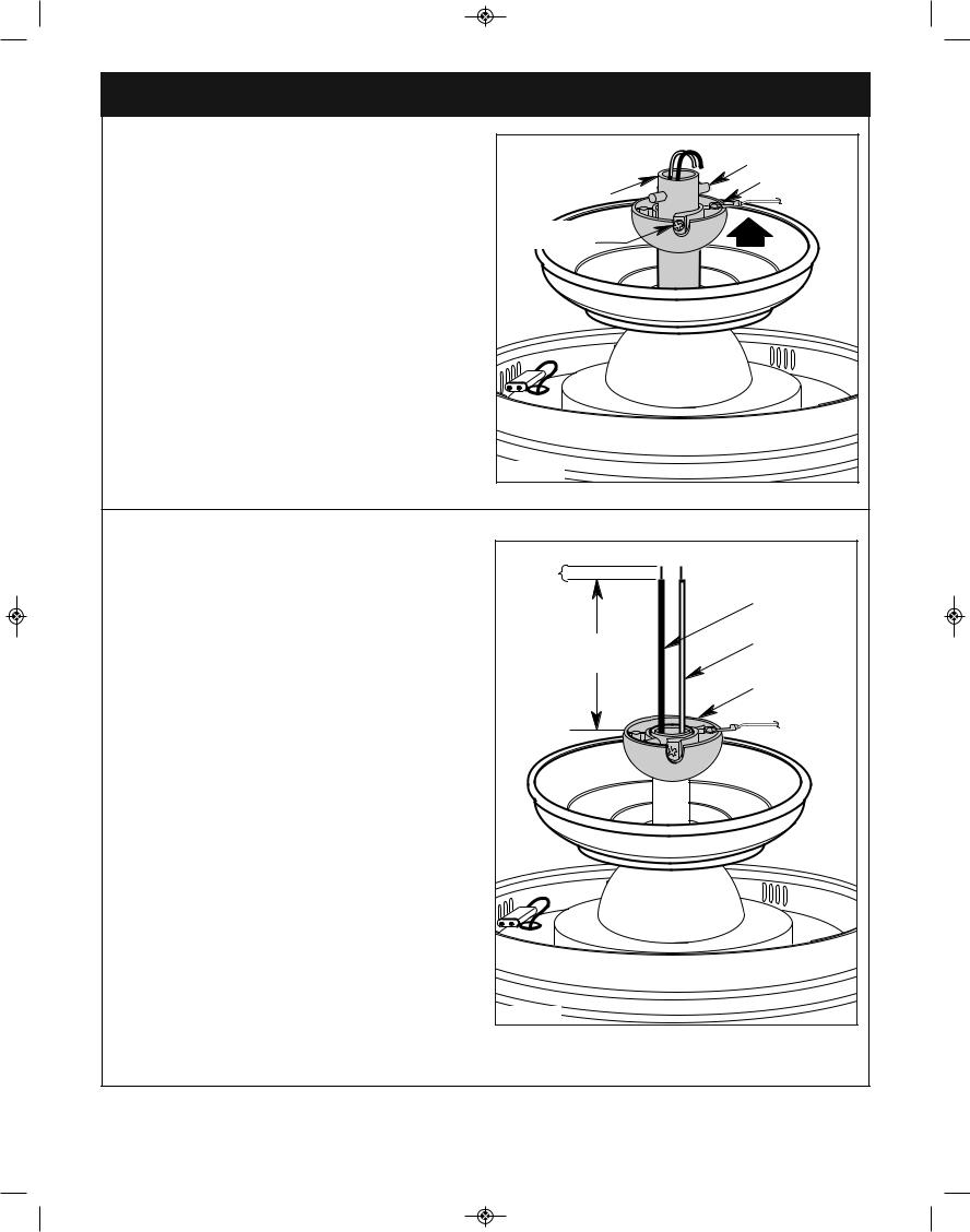
|
3.8
The fan comes with black and white leads that are 80” long.
Measure up approximately 6 to 9-inches above top of hanger ball/4.5” downrod assembly (Figure 8).
Cut off excess leads and strip back insulation 1/2-inch from end of leads.
1/2-INCH |
|
|
BLACK WIRE |
6 TO 9 |
WHITE WIRE |
INCHES |
|
|
HANGER BALL |
Figure 8 |
|
|
emersonfans.com |
7 |
Please contact 1-800-654-3545 for further assistance |
ETL Model No.: CF5200 |
BP7511-1 CF5200 Penbrooke Select Eco.qxp_ BP7511 2/8/16 12:02 PM Page 8 |
|
|
|
|
3. Ceiling Fan Assembly (Continued) |
||
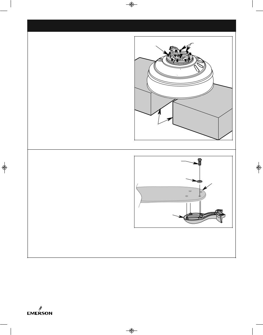
3.9 |
|
|
REMOVE & DISCARD |
Carefully turn the partially assembled ceiling fan upside |
PARTIALLY |
5 RUBBER SHIPPING |
|
down, place the ceiling fan onto the two carton styrofoam |
ASSEMBLED |
SPACERS & 10 SCREWS |
|
pieces, in preparation for final assembly (Figure 9). |
CEILING FAN |
|
|
|
|
||
Remove each of the ten spacer screws and five rubber |
|
|
|
shipping spacers from the motor hub before installation of |
|
|
|
blade assemblies (Figure 9). |
|
|
|
Discard the five rubber shipping spacers and ten spacer |
|
|
|
screws. |
|
|
|
|
|
STYROFOAM |
|
|
|
PIECES |
|
|
|
Figure 9 |
|
3.10 |
|
#10-24 x 12mm |
|
NOTE: Your ceiling fan will operate with the following |
ROUND HEAD SCREW |
|
|
Blade Select Blades (Sold Separately): |
(4 per blade/flange) |
|
|
FLAT WASHER |
|
||
B77, B78, B79, B90, B91, B92, B97, B100, B101, B102, |
|
||
(4 per blade/flange) |
|
||
B103, B107, B108, B109, G44, G54, & G60. |
|
FAN BLADE |
|
Mount the fan blade (sold separately) using the four |
|
(sold |
|
|
separately) |
||
#10-24 x 12mm round head screws and flat washers |
|
|
|
(supplied in parts bag) to secure flange to blade |
|
|
|
(Figure 10). |
|
|
|
Repeat for the remaining four blades.
BLADE FLANGE
Make sure all screws are tighten securely in the fan blade
NOTE:and flangeSome. accessory blades are supplied with Figure 10 shorter screws. These shorter screws MUST be used
to assemble the blades to flanges.
8 |
ETL Model No.: CF5200 |
 BP7511-1 CF5200 Penbrooke Select Eco.qxp_ BP7511 2/8/16 12:02 PM Page 9
|
3. Ceiling Fan Assembly (Continued) |
||
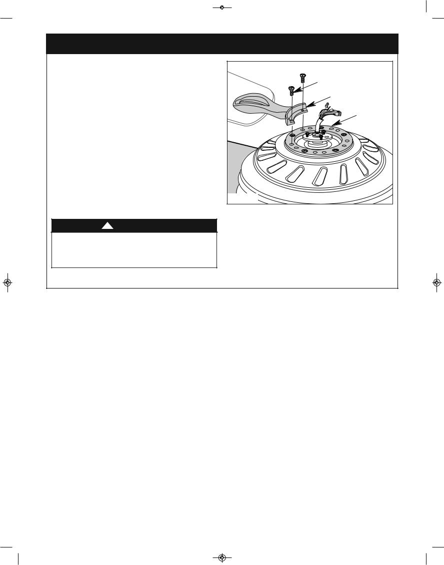
3.11 |
|
#10-32 x 5/8" OVAL |
|
Loosely attach one blade/flange assembly to the motor |
HEAD SCREW |
||
(2 per blade/flange) |
|||
hub by securing the two #10-32 x 5/8” oval head screws |
|||
|
|||
(supplied in parts bag) (Figure 11). |
BLADE/FLANGE |
||
Install remaining blade assemblies in the same way. |
ASSEMBLY |
||
|
|||
Gently snug all flange screws to the motor hub, working |
MOTOR |
||
around the hub in a clockwise sequence. |
HUB |
||
The blade flanges have an interlocking feature that must |
|
||
be fully engaged before tightening the screw. Make sure all |
|
||
the flanges are properly engaged and then tighten the |
|
||
flange screws. If one of the flanges does not seat properly |
|
||
on the motor hub, loosen the adjacent flange screws, re- |
|
||
engage and reseat the flanges, then tighten the screws |
|
||
NOTE: Take care not to scratch fan housing when |
|
||
again. |
|
|
|
installing blades. |
|
Figure 11 |
|
|
|
||
! |
WARNING |
|
|
To reduce the risk of personal injury, do not bend the |
|
||
blade flange when installing the blade flanges, |
|
||
balancing the blades or cleaning the fan. Do not insert |
|
||
foreign objects in between rotating fan blades. |
|
||
|
emersonfans.com |
9 |
Please contact 1-800-654-3545 for further assistance |
ETL Model No.: CF5200 |
 Loading...