


READ AND SAVE THESE INSTRUCTIONS
|
ST CROIX™ |
|
Damp Location |
|
Ceiling Fan |
|
Owner's Manual |
|
Model Numbers |
Two Person Installation Required |
CF3300AP |
Blades & Downrod Kit Sold Separately |
|
Net Weight: 44.8 Lbs. |
CF3300ORH |
LIMITED WARRANTY
What The Warranty Covers:
This warranty covers the motor and the other components and accessories of your Emerson ceiling fan against all defects in workmanship and materials. You must be the original purchaser or user of the product to be covered.
What The Period Of Coverage Is:
As it applies to the motor, this warranty will last for a lifetime of your ceiling fan. All other components and accessories are covered by this warranty for one year from the date you purchased your ceiling fan. ANY IMPLIED WARRANTY OF MERCHANTABILITY OR FITNESS FOR A PARTICULAR PURPOSE, MADE WITH RESPECT TO COMPONENTS AND ACCESSORIES IS ALSO LIMITED TO ONE YEAR.
What Will Emerson Electric Co. Do To Correct Problems:
Emerson Electric Co. will replace a defective Emerson Air Comfort Ceiling Fan motor, blade, component or other accessory at no charge to you. If repair of the motor or blades is not practical or possible within a reasonable time and no replacement can be provided, Emerson will refund the actual purchase price of your fan. WE WILL SHIP THE REPAIRED PRODUCT OR REPLACEMENT TO YOU AT NO CHARGE, BUT YOU ARE RESPONSIBLE FOR ALL COSTS OR
REMOVAL, REINSTALLATION AND SHIPPING OF THE PRODUCT TO EMERSON ELECTRIC CO.
How Can You Get Service:
YOU MUST HAVE PROOF OF YOUR PURCHASE OF THE CEILING FAN TO OBTAIN LIMITED WARRANTY SERVICE. KEEP YOUR RECEIPT OR OTHER PROOF OF PURCHASE. You can return the product to our factory or to your nearest authorized service center.
•To return the product to the factory, obtain a return authorization and service identification tag by writing to Air Comfort Products, Division of Emerson Electric Co., 8100 W. Florissant Ave., St. Louis, MO 63136. Include all model numbers shown on the product with your request.
•To return the product to an authorized service center, call 1-800-654-3545 for the address of the nearest authorized service center.
You will be responsible for all insurance, freight or other transportation charges to our factory or authorized service center. Your Emerson Air Comfort Ceiling Fan should be properly packed to avoid damage in transit since we will not be responsible for any such damage.
What Is Not Covered:
The glass globes and light bulbs of your ceiling fan are not covered by this warranty. This warranty also does not cover any defects, malfunctions or failures caused by:
•Repairs by persons not authorized by Emerson Electric Co.,
•Use of parts or accessories not authorized by Emerson Electric Co.,
•Mishandling, improper installation, modifications or damage to your ceiling fan while in your possession, or
•Unreasonable use, misuse, abuse, including failing to do reasonable and necessary maintenance, and normal wear and tear. Additionally, this warranty and any implied warranty of merchantability or fitness for a particular purpose are voided when:
•The original purchaser or user ceases to own the product, or
•The fan is moved from its original point of installation.
This warranty is only valid within the 50 states of the United States and the District of Columbia. No other written or oral warranties apply, and no employee, agent, dealer or other person is authorized to give any warranties on behalf of Emerson Electric Co.
REPAIR, REPLACEMENT OR A REFUND ARE THE EXCLUSIVE REMEDIES AVAILABLE UNDER THIS WARRANTY AND EMERSON IS NOT RESPONSIBLE FOR DAMAGES OF ANY KIND, INCLUDING INCIDENTAL AND CONSEQUENTIAL DAMAGES. Incidental damages include but are not limited to such damages as loss of time and loss of use. Consequential damages include but are not limited to the cost of repairing or replacing other property which was damaged if this product does not work properly.
How State Law Relates To The Warranty:
Some states do not allow the exclusion or limitation of incidental or consequential damages so the above exclusion or limitation may not apply to you. This warranty gives you specific legal rights, and you may also have other rights which vary from state to state.
Part No. F40BP73850000 |
Form No. BP7385 |
|
U.L. Model No.: CF3300 |
!WARNING
WARNING: To avoid fire, shock, and serious personal injury, follow these instructions.
Safety Instructions
1.Read your owner’s manual carefully and keep it for future reference.
2.Before servicing or cleaning unit, switch power off at service panel and lock service panel disconnecting means to prevent power from being switched on accidentally. When the service disconnecting means cannot be locked, securely fasten a warning device, such as a tag, to the service panel.
3.Be careful of the fan and blades when cleaning, painting, or working near the fan. Always turn off the power to the ceiling fan before servicing.
4.Do not put anything into the fan blades while they are turning.
5.Do not operate reversing switch until fan blades have come to a complete stop.
Additional Safety Instructions for Installation
1.To avoid possible shock, be sure electricity is turned off at the fuse box before wiring, and do not operate fan without blades.
2.All wiring must be in accordance with the National Electrical Codes “ANSI/NFPA 70-1999” and Local Electrical Codes. Use the National Electrical Code if Local Codes do not exist. The ceiling fan must be grounded as a precaution against possible electrical shock. Electrical installation should be made or approved by a licensed electrician.
3.The fan mounting bracket must be surely mounted and capable of reliably supporting at least 100 lbs. Outlet boxes are not acceptable for fan support. See Page 6 of owner’s manual for support requirements. Consult a qualified electrician if in doubt.
CAUTION: To reduce the risk of personal injury, mount the fan base to a ceiling joist or structural member using the hardware provided with your fan.
WARNING: Support Directly from Building Structure.
4.The fan must be mounted with the fan blades at least 7 feet from the floor to prevent accidental contact with the fan blades.
5.Follow the recommended instructions for the proper method of wiring your ceiling fan. If you do not know enough about electrical wiring, have your fan installed by a licensed electrician.
WARNING: To avoid fire, shock or injury, do not use an Emerson or any other brand of control not specifically approved for this fan.
WARNING: This product is designed to use only those parts supplied with this product and/or any accessories designated specifically for use with this product by Emerson Electric Co. Substitution of parts or accessories not designated for use with this product by Emerson Electric Co. could result in personal injury or property damage.
WARNING: To reduce the risk of personal injury, do not bend the blade flange when installing the blade flanges, balancing the blades or cleaning the fan. Do not insert foreign objects in between rotating fan blades.
NOTE: This fan is suitable for use with solid-state speed controls.
WARNING: To reduce the risk of fire or electric shock, this fan should only be used with fan speed control SW22, manufactured by Rhine Electric Co., Ltd.
WARNING: To reduce the risk of electrical shock, this fan must be installed with an isolating wall control/switch.
WARNING: To reduce the risk of fire, electric shock, and injury to persons, ceiling fan must be installed with fan blades and light kits that are marked to indicate the suitability with this model. Other blades and light kits can not be substituted.
DATE CODE:
The date code of this fan may be found on the box, stamped in ink on a white label. You should record this data above and keep it in a safe place for future use.
2 |
U.L. Model No.: CF3300 |
THIS FAN IS SUITABLE FOR DAMP LOCATIONS
SUCH AS COVERED PORCHES, COVERED PATIOS, AND COVERED DECKS...ANYWHERE THERE IS A ROOF OVERHEAD.
Tools Needed for Assembly
One Phillips head screwdriver |
One stepladder |
One 1/4” blade screwdriver |
One wire stripper |
One 5/16” open end wrench or pliers
7/16”, 1/2” & 9/16” wrench or socket wrench One 1/4” drill bit
MATERIALS
Wiring outlet box and box connectors must be of type required by the local code. The minimum wire would be a 3-conductor (2-wire with ground) of following size:
Installed Wire Length |
Wire Size A.W.G. |
Up to 50 ft. |
14 |
50-100 ft. |
12 |
!WARNING
Before you assemble your ceiling fan, refer to section on proper method of wiring your fan (page 8). If you feel you do not have enough wiring knowledge or experience, have your fan installed by a licensed electrician.
Unpacking Instructions
For your convenience, check-off boxes are provided next to each step. As each step is completed, place a check mark in the box. This will insure that all steps have been completed and will be helpful in finding your place should you be interrupted.
!WARNING
Do not install or use fan if any part is damaged or missing. Call Toll-Free:
1-800-654-3545
!WARNING
This product is designed to use only those parts supplied with this product and/or any accessories designated specifically for use with this product by Emerson Electric Co. Substitution of parts or accessories not designated for use with this product by Emerson could result in personal injury or property damage.
1.Check to see that you have received the following parts:
NOTE: If you are uncertain of part description, refer to exploded view illustration.
NOTE: Blades and downrod kit sold separately.
m.Mounting bracket bag, containing:
1.One 3/8 x 2” lag bolt
2.One 3/8 x 5” lag bolt
3.Two 3/8” flat washers
4.One brass barrel nut
5.One bushing
6.One ceiling support cable
7.One 5/32 x 10mm phillips screw
n.One hardware bag, containing:
1.Five wire connectors
2.One 1/16” hex wrench
3.One clevis pin
4.One hair pin clip
5.Two threaded studs
6.Two lockwashers
7.Two knurled knobs
8.Two 5/16-18 x 1/4” cup point setscrews
9.One 3/16” hex wrench
o.One flange assembly bag, containing:
1.Seventeen #8-32 x 15mm flat head screws
p.Two blade assembly bags, each containing:
1.Twenty-five #10-32 x 18mm oval head screws
a. Fan assembly |
|
q. One downrod assembly bag, containing: |
b. Two fan motor covers |
|
1. Nine 1/4 x 10mm round head screws |
|
|
|
c. One decorative downrod sleeve |
|
NOTE: Keep all bags unopened until time of |
d. One upper decorative downrod sleeve |
|
assembly. Then place the parts from each loose |
assembly |
|
parts bags in a small container to keep them from |
e. One decorative strap ring |
|
being lost. If any parts are missing, contact your |
f. One ceiling canopy |
|
local retailer or catalog outlet for replacement |
|
before proceeding. |
|
g. Four right hand blade flanges |
|
|
|
2. Remove the fan assembly from the protective |
|
h. Four left hand blade flanges |
|
|
i. One hanger ball/downrod extension assembly |
|
plastic bag. Place the fan assembly into the foam |
|
||
j. One hanger bracket assembly |
|
pad with the downrod coupling facing up. |
|
The foam pad serves as a holder for the fan during |
|
k. Eight blade medallions |
|
|
|
the first stages of assembly. |
|
l. One SW22 wall control with almond and |
|
|
|
|
|
white knobs |
3 |
U.L. Model No.: CF3300 |
|

F. DECORATIVE |
|
|
|
STRAP RING |
|
|
A. FAN |
D. UPPER |
|
|
|
|
M. SW22 |
ASSEMBLY |
|
DECORATIVE |
|
|
|
|
WALL |
|
|
DOWNROD SLEEVE |
|
|
|
OFF |
CONTROL |
|
|
|
|
|
B. FAN MOTOR |
|
C. DECORATIVE DOWNROD |
COVERS (2) |
|
|
|
SLEEVE ASSEMBLY |
|
|
|
|
|
H. RIGHT HAND |
M. MOUNTING |
|
BLADE FLANGES (4) |
|
|
BRACKET BAG |
|
|
I.LEFT HAND BLADE |
|
|
|
|
|
FLANGES (4) |
|
|
|
N. HARDWARE |
|
|
BAG |
|
G. CEILING |
|
L. BLADE |
CANOPY |
O. FLANGE |
|
||
MEDALLIONS (8) |
E. DOWNROD |
ASSEMBLY |
|
EXTENSION |
BAG |
|
K. HANGER BRACKET |
P. BLADE |
|
ASSEMBLY |
|
|
ASSEMBLY |
|
|
J. HANGER BALL/ |
BAGS |
|
|
|
|
DOWNROD |
Q. DOWNROD |
|
EXTENSION |
|
|
ASSEMBLY |
|
|
|
BAG |
How to Put Your Ceiling Fan Together
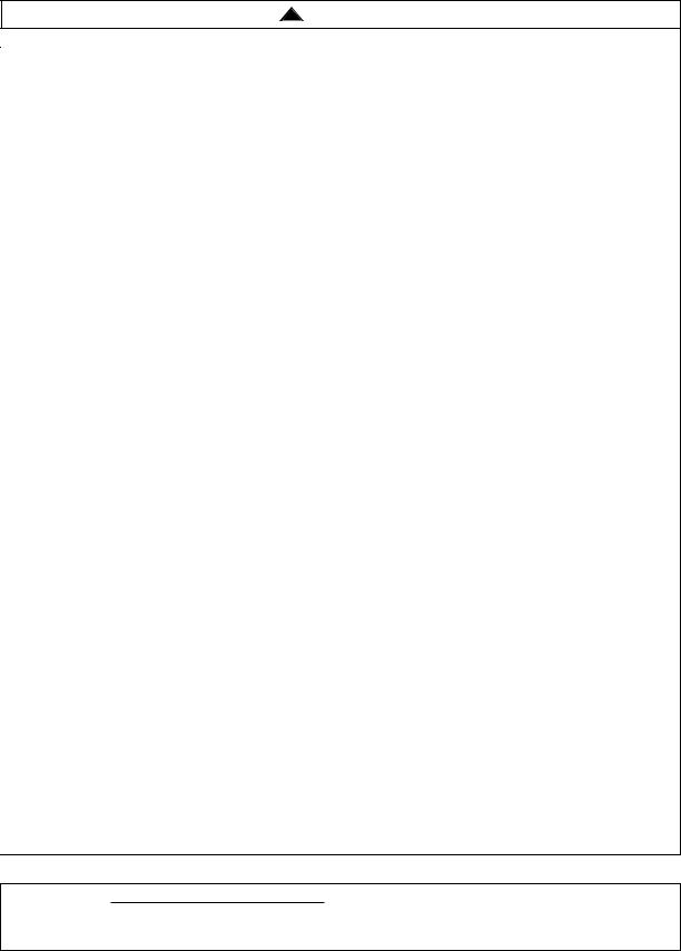
1. Loosely install both 5/16-18 x 1/4” cup point |
|
|
|
|
|
|
setscrews (supplied) into the downrod coupling. |
|
|
|
|
|
|
Separate, untwist and unkink the three 80” motor |
|
|
|
|
DOWNROD |
|
leads and support wire. Route the motor lead wires |
|
|
|
|
EXTENSION |
|
|
|
|
|
|
|
|
and support wire through the downrod extension. |
|
|
|
CLEVIS PIN |
HAIRPIN |
|
Align the clevis pin holes in the downrod extension |
|
|
|
CLIP |
||
|
|
|
|
|
|
|
with the holes in the downrod coupling. Install the |
|
|
|
|
|
|
clevis pin and secure with the hairpin clip |
|
|
|
|
|
|
(Figure 1). The clevis pin must go through the |
|
|
|
DOWNROD |
5/16-18 x 1/4" CUP |
|
holes in the downrod coupling and the holes in the |
|
|
|
|||
|
|
|
POINT SETSCREW (2) |
|||
downrod extension. Be sure to push the straight leg |
|
|
|
COUPLING |
||
|
|
|
|
|
|
|
of the hairpin clip through the hole near the end of |
|
|
|
|
|
|
the clevis pin until the curved portion of the hairpin |
|
|
|
|
|
|
clip snaps around the clevis pin. The hairpin clip |
|
|
|
|
|
|
must be properly installed to prevent the clevis pin |
|
|
|
|
|
|
from working loose. Pull on the downrod extension |
|
|
|
|
|
|
to make sure the clevis pin is properly installed. |
|
|
|
|
|
|
|
|
|
Figure 1 |
|
||
|
|
|
|
|
For ease of installation, loosely tape the |
|
2. While pulling up on the downrod extension, |
|
|
|
NOTE: |
||
securely tighten the two setscrews in the downrod |
|
|
|
ends of the motor leads and the support wire |
||
coupling using the 3/16” hex wrench (supplied). |
|
|
|
together to route through downrod during fan |
||
The setscrews must be tightened into the downrod |
|
|
|
installation. |
|
|
extension. A loose extension downrod will result |
|
|
|
3. Route the motor leads and support wire through |
||
|
|
|
||||
with fan assembly noise and vibration. |
|
|
|
|||
|
|
|
the downrod (Figure 2). |
|
||
|
|
|
|
|||
|
|
|
|
|
||
|
|
|
|
4. Securely attach the downrod to the downrod |
||
! WARNING |
|
|
|
|||
|
|
|
||||
|
|
|
|
extension using the four 1/4 x 10mm round head |
||
It is critical that the clevis pin in the downrod |
|
|
|
|||
|
|
|
screws (supplied in the downrod assembly bag). |
|||
coupling is properly installed and the |
|
|
|
|||
|
|
|
The round head screws must be fully tightened into |
|||
setscrews securely tightened. Failure to verify |
|
|
|
|||
that the pin and setscrews are properly |
|
|
|
the downrod extension. A loose downrod will result |
||
installed (as shown in Figure 1) could result in |
|
|
|
with fan assembly noise and vibration. |
||
the fan falling. |
4 |
|
|
|
U.L. Model No.: CF3300 |
|
|
|
|
|
|||
|
|
|
||||
DOWNROD
1/4 x 10mm ROUND
HEAD SCREW (4)
DOWNROD
EXTENSION
Figure 2
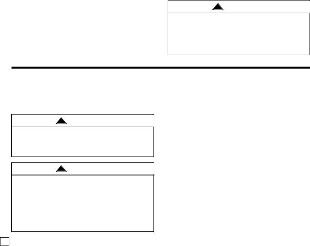
5.Route the motor lead wires and support wire through the decorative downrod sleeve assembly. Carefully slide the decorative downrod sleeve assembly over the downrod and set firmly on downrod coupling (Figure 3).
6.Using the hex wrench (supplied), tighten the three setscrews located at the top of the decorative downrod sleeve assembly (Figure 3).
NOTE: It is important that all setscrews are securely tightened and the decorative downrod sleeve assembly is secure. To not overtighten setscrews.
DOWNROD
SETSCREW (3) 
DECORATIVE
DOWNROD SLEEVE
ASSEMBLY
7.Route the motor lead wires and support wire through the upper decorative downrod sleeve and the decorative strap ring (Figure 4). Careful not to scratch the downrod with the sleeve and ring during installation.
NOTE: Be careful not to scratch the downrod during installation.
8.Position the upper decorative downrod sleeve and the decorative strap ring just above the decorative downrod sleeve assembly during initial installation (Figure 4).
DOWNROD
DECORATIVE
STRAP RING
UPPER DECORATIVE
DOWNROD SLEEVE
DOWNROD
SETSCREW (3)
Figure 4
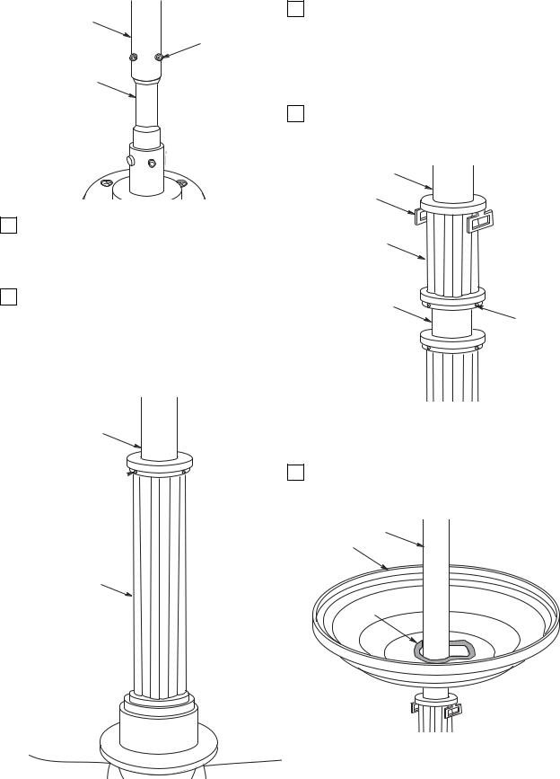
NOTE: Apply masking tape to the entire edge of the ceiling canopy center hole to prevent accidental scratching of downrod surface (Figure 5).
9.Route the motor lead wires and support wire through the ceiling canopy (Figure 5). Use extreme caution not to scratch the downrod with the ceiling canopy during installation.
DOWNROD
CEILING
CANOPY
MASKING
TAPE
Figure 5
NOTE: Be careful not to scratch the downrod during installation.
Figure 3 |
5 |
U.L. Model No.: CF3300 |
|
 Loading...