


READ AND SAVE THESE INSTRUCTIONS
VELOCE
Ceiling Fan Owner's Manual
Model Numbers
CF230BS00
CF230ORB00
CF230WW00
Net Weight: 17.0 Lbs.
Part No. F40BP74340001 |
Form No. BP7434-1 |
|
U.L. Model No.: CF230 |
!WARNING
WARNING: To avoid fire, shock, and serious personal injury, follow these instructions.
Safety Instructions
1.Read your owner’s manual carefully and keep it for future reference.
2.Before servicing or cleaning unit, switch power off at service panel and lock service panel disconnecting means to prevent power from being switched on accidentally. When the service disconnecting means cannot be locked, securely fasten a warning device, such as a tag, to the service panel.
3.Be careful of the fan and blades when cleaning, painting, or working near the fan. Always turn off the power to the ceiling fan before servicing.
4.Do not put anything into the fan blades while they are turning.
5.Do not operate reversing switch until fan blades have come to a complete stop.
Additional Safety Instructions for Installation
1.To avoid possible shock, be sure electricity is turned off at the fuse box before wiring, and do not operate fan without blades.
2.All wiring must be in accordance with the National Electrical Codes “ANSI/NFPA 70-2008” and Local Electrical Codes. Use the National Electrical Code if Local Codes do not exist. The ceiling fan must be grounded as a precaution against possible electrical shock. Electrical installation should be made or approved by a licensed electrician.
3.The ceiling structure must be capable of reliably supporting at least 50 pounds.
4.Use only U.L. outlet boxes listed as “Acceptable for Fan Support of 15.9 kg (35 lbs) or less”, and use the mounting screws provided with the outlet box. Most outlet boxes commonly used for support of light fixtures are not acceptable for fan support and may need to be replaced. Consult a qualified electrician if in doubt.
5.The fan must be mounted with the fan blades at least 7 feet from the floor to prevent accidental contact with the fan blades.
6.Follow the recommended instructions for the proper method of wiring your ceiling fan. If you do not know enough about electrical wiring, have your fan installed by a licensed electrician.
CAUTION: To reduce the risk of electric shock, disconnect the electrical supply circuit to the fan before light kit.
7.Use only with light kits marked suitable for use in damp locations” to the Additional Safety Instructions for Installation.
NOTE: All set screws must be checked and re-tightened where necessary before installation.
WARNING: To reduce the risk of fire or electrical shock, do not use this fan with any solid-state speed control device.
WARNING: To avoid fire, shock or injury, do not use on Emerson or any other brand of control not specifically approved fro this fan.
WARNING: To reduce the risk of fire or electric shock, this fan should only be used with fan speed control, Model No. SR401/U.L. Model No. UC7067RAL manufactured by Rhine Electric Co., Ltd.
WARNING: To avoid fire, shock or injury, do not use an Emerson or any other brand of control not specifically approved for this fan.
WARNING: This product is designed to use only those parts supplied with this product and/or any accessories designated specifically for use with this product by Emerson Electric Co. Substitution of parts or accessories not designated for use with this product by Emerson Electric Co. could result in personal injury or property damage.
WARNING: To reduce the risk of personal injury, do not bend the blade flange when installing the blade flanges, balancing the blades or cleaning the fan. Do not insert foreign objects in between rotating fan blades.
WARNING: To reduce the risk of electric shock, this fan must be installed with an isolating wall control/switch.
DATE CODE:
The date code of this fan may be found on the box, stamped in ink on a white label. You should record this data above and keep it in a safe place for future use.
2 |
U.L. Model No.: CF230 |
This Manual Is Designed to Make it as Easy as Possible for You to Assemble, Install, Operate and Maintain Your Ceiling Fan
THIS FAN IS SUITABLE FOR DAMP LOCATIONS SUCH AS COVERED PORCHES, COVERED PATIOS,
AND COVERED DECKS...ANYWHERE THERE IS A ROOF OVERHEAD.
USE ONLY WITH LIGHT KITS MARKED SUITABLE FOR USE IN DAMP LOCATIONS.
Tools Needed for Assembly
One Phillips head screwdriver |
One stepladder |
One 1/4” blade screwdriver |
One wire stripper |
MATERIALS
Wiring outlet box and box connectors must be of type required by the local code. The minimum wire would be a 3-conductor (2-wire with ground) of the following size:
Installed Wire Length |
Wire Size A.W.G. |
Up to 50 ft. |
14 |
50-100 ft. |
12 |
|
|
!WARNING
Before assembly your ceiling fan, refer to section on proper method of wiring your fan (page 9 or 12). If you feel you do not have enough wiring knowledge or experience, have your fan installed by a licensed electrician.
Unpacking Instructions
!WARNING
Do not install or use fan if any part is damaged or missing. Call Toll-Free:
1-800-654-3545
!WARNING
This product is designed to use only those parts supplied with this product and/or any accessories designated specifically for use with this product by Emerson Electric Co. Substitution of parts or accessories not designated for use with this product by Emerson Electric Co. could result in personal injury or property damage.
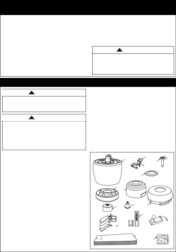
1.Open carton containing fan. Remove top half of styrofoam unit. Remove parts and check to see that you have received the following parts:
NOTE: If you are uncertain of part description, refer to exploded view illustration.
a.Fan motor assembly
b.One hanger bracket
c.One 4.5” downrod assembly
d.One ceiling cover trim ring
e.One ceiling cover with trim plugs
f.One lower cover
g.One light kit plate assembly
h.One coupler cover
i.Four fan blade flanges
j.Four fan blades
k.One 50 watt GU10 base light bulb
l.RCFP-190 receiver & SR400 transmitter
m.One loose parts bag containing:
1.Three 12 ga. wire connectors
2.Thirteen #10-24 x 5/16" flange head blade screws
3.Four #10-24 x 3/16" pan head screws
4.Four #10 external tooth lockwasher
5.One rubber gasket
6.One #8-32 x 5/16” light switch screw (spare)
7.One 1/4-20 x 9/16” flange screw with lockwasher (spare)
8.Two threaded stud, #8-32 x 1-1/4”
9.Two external tooth lockwashers
10.Two knurled knobs, #8-32
11.One clevis pin
12.One hairpin clip
13.One balancing kit
NOTE: Place the parts from the loose parts bags in a small container to keep them from being lost. If any parts are missing, contact your local retailer or catalog outlet for replacement before proceeding.
2.Remove the fan assembly from the protective plastic bag. Place the fan assembly into the upper foam pad with the lead wires up.
b.
a.
c.
d.
g.
e.
k.
h. 
 f.
f.
l.  l.
l.

 i.
i.
 j.
j.
m.
3 |
U.L. Model No.: CF230 |
Electrical Requirements
Your new ceiling fan will require a grounded electrical supply line of 120 volts AC, 60 Hz, 15 amp circuit.
The ceiling structure must be capable of reliably supporting at least 50 pounds.
!WARNING
To reduce the risk of fire, electrical shock, or personal injury, mount fan to outlet box marked “Acceptable for Fan Support of 15.9 kg (35 lbs) or less", and use screws supplied with outlet box. Most outlet boxes commonly used for support of light fixtures are not acceptable for fan support and may need to be replaced. Consult a qualified electrician if in doubt.
If your fan is to replace an existing ceiling light fixture, turn electricity off at the main fuse box at this time and remove the existing light fixture.
Your Emerson ceiling fan comes supplied with a Fan Remote Control which consists of a wall mounted switch which allows you to regulate your ceiling fan speed.
!WARNING
Turning off wall switch is not sufficient. To avoid possible electrical shock, be sure electricity is turned off at the main fuse box before wiring. All wiring must be in accordance with National and Local codes and the ceiling fan must be properly grounded as a precaution against possible electrical shock.
!WARNING
To avoid fire or shock, follow all wiring instructions carefully. Any electrical work not described in these instructions should be done or approved by a licensed electrician.
IMPORTANT: Your ceiling fan will not function properly, and may be damaged, if used with any wall dimmer switch or control other than the Emerson Electric Fan/Light Remote Control supplied with the fan.
Installation of Hanger Bracket
IMPORTANT
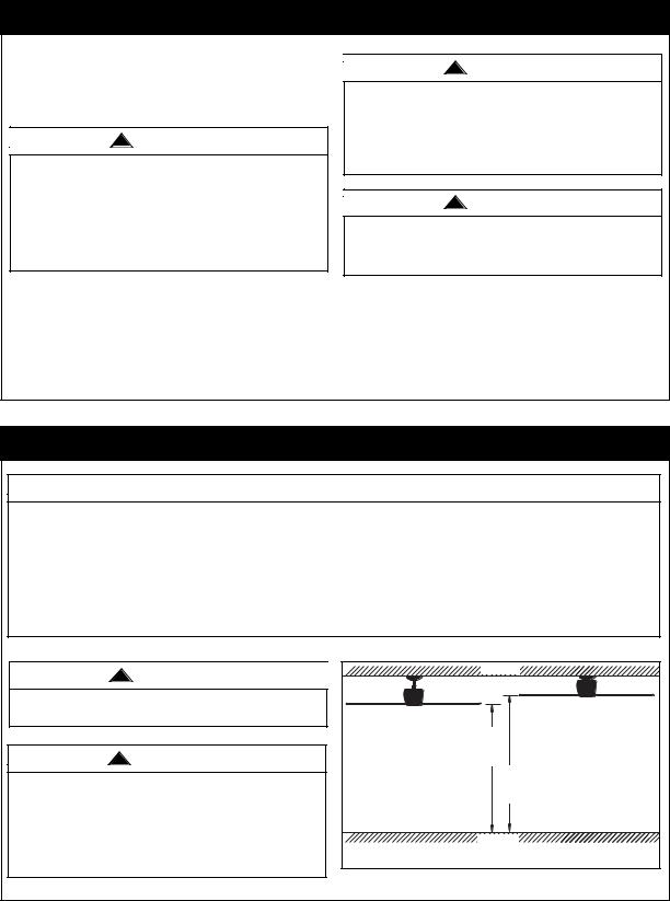
Your Emerson Ceiling is designed to be installed either in the standard manner, or in the close-to-the- ceiling manner. Using the standard method, the hanger ball/downrod assembly will suspend the fan several inches below the ceiling cover. Using the close-to-the-ceiling method, the ceiling cover installs directly on the fan motor housing, thus mounting the fan 3-1/2 inches closer to the ceiling than the standard methond. In no case should the fan blades be lower than seven feet above the floor. Depending on your desire mounting method, proceed to ‘INSTALLING HANGER BALL/DOWNROD ASSEMBLY” for standard mounting, or to “INSTALLING CEILING COVER ON FAN MOTOR HOUSING” for close-to-the-ceiling mounting.
!WARNING
The fan must be hung with at least 7' of clearance from floor to blades (Figure 1).
!WARNING
To reduce the risk of fire, electrical shock, or personal injury, mount fan to outlet box marked “Acceptable for Fan Support of 15.9 kg (35 lbs) or less", and use screws supplied with outlet box. Most outlet boxes commonly used for support of light fixtures are not acceptable for fan support and may need to be replaced. Consult a qualified electrician if in doubt.
|
CEILING |
|
CLOSE-TO-THE-CEILING |
STANDARD |
INSTALLTION |
INSTALLTION |
AT |
|
LEAST |
|
7' |
|
AT |
|
LEAST |
|
7' |
|
FLOOR |
Figure 1 |
|
4 |
U.L. Model No.: CF230 |
Installation of Hanger Bracket (continued)
!WARNING
Turning off wall switch is not sufficient. To avoid possible electrical shock, be sure electricity is turned off at the main fuse box before wiring. All wiring must be in accordance with National and Local codes and the ceiling fan must be properly grounded as a precaution against possible electrical shock.
1.Disconnect electrical power to the branch circuit at the circuit breaker or fuse box before attempting to install the ceiling fan mounting plate on the outlet box.
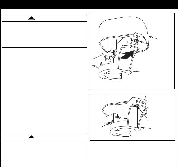
2.Loosen (but do not remove) the two mounting screws in the outlet box (Figure 2). Position the hanger bracket on the outlet box so that the T-slots in the hanger bracket are aligned with the outlet box screws.
|
OUTLET BOX |
|
LOOSEN TWO |
T-SLOT |
SCREWS (SUPPLIED |
WITH OUTLET BOX) |
|
|
SLIDE THE HANGER |
|
BRACKET ONTO |
|
THE OUTLET BOX |
|
SCREWS, THROUGH |
|
THE T-SLOT |
|
HANGER |
|
BRACKET |
Figure 2 |
|
NOTE: The hanger bracket must be mounted flush with the ceiling in order for the ceiling cover to install properly. If necessary, use leveling washers (not supplied) between the outlet box and the hanger bracket.
3.Slide the hanger bracket onto the outlet box screws. Center the bracket over the outlet box and then securely tighten the screws (Figure 3).
!WARNING
Hanger bracket must seat firmly against outlet box. If the outlet box is recessed, remove wall board until bracket contacts box. If bracket and/or outlet box are not securely attached, the fan could wobble or fall.
 SECURELY TIGHTEN
SCREWS
HOOK |
HANGER BRACKET |
|
Figure 3
5 |
U.L. Model No.: CF230 |

Installation of Blades & Light Assembly
1.Mount the blade flanges to the fan blades using three #10-24 x 5/16” Phillips blade screws per blade (supplied) (Figure 4). Repeat for the three remaining blades.
!WARNING
To reduce the risk of personal injury, do not bend the blade flange when installing the blade flanges, balancing the blades or cleaning the fan. Do not insert foreign objects in between rotating fan blades.
2.Attach one blade assembly to the motor using the captive screw provided for each flange (Figure 5). Make sure the screws are tightened securely. Repeat this procedure for the other three blade assemblies.
NOTE: Take care not to scratch the fan housing when installing the blade assemblies.
3.Remove one of the fan motor assembly screw (and retain for later use) and loosen the two other screws for installation of the light kit plate assembly (Figure 6).
4.Remove and retain the wire connectors from the white and blue wires (Figure 6).
5.Connect the white wire from the ceiling fan to the white wire of the light kit plate (Figure 7). Connect the blue wire from the ceiling fan to the black wire of the light kit plate. Use wire connectors (previously removed) to make connections.
NOTE: Carefully tuck all wires and connectors into the fan motor assembly.
!WARNING
To avoid possible fire or shock, make sure that electrical wires are not pinched between the light kit plate assembly and the fan motor assembly.
10-24 x 5/16" FLANGE HEAD BLADE SCREW (3 Per Blade)
FAN BLADE
FAN BLADE 
FLANGE
Figure 4
|
CAPTIVE SCREW |
MOTOR |
BLADE FLANGE |
HOUSING |
ASSEMBLY |
Figure 5
REMOVE AND RETAIN |
FAN MOTOR SCREW |
REMOVE AND RETAIN |
WIRE CONNECTORS (2) |
LOOSEN TWO FAN |
MOTOR SCREWS |
Figure 6 |
|
|
LIGHT KIT PLATE |
|
|
ASSEMBLY |
|
REINSTALL WIRE |
LIGHT SWITCH |
|
BLACK WIRE |
|
|
CONNECTORS |
|
|
|
|
|
|
LIGHT SWITCH |
|
|
WHITE WIRE |
|
|
FAN MOTOR |
|
|
BLUE WIRE |
|
|
FAN MOTOR |
Figure 7 |
|
WHITE WIRE |
|
|
6 |
U.L. Model No.: CF230 |
 Loading...