


Installation
Manual
Catalog 5110
Accessory 72A Serial Module
for 4000 Series, 7000 Series, & Series 300 ATSs
Contents of Accessory 72A Kit 755257
Serial Module |
DIN Rail & |
10–inch |
|
Hardware |
Serial Cable |
||
|
|||
|
|
|
|
629750 |
754607 |
629798–001 |
|
|
|
|
|
|
|
|
Refer to the wiring diagrams and drawings provided with the automatic transfer switch (ATS).
The ASCO Catalog 5110 Serial Module (optional Accessory 72A) is required with 4000 Series, 7000 Series, or Series 300 Automatic Transfer Switches (ATSs) for serial communications. With this option installed, the ATS Controller can respond to requests (from ASCO devices) to send the status of standard features and optional accessories. In addition, the controller can receive remote commands to control the operation of the ATS.
This manual explains how to install the Serial Module on 4000 Series, 7000 Series, and Series 300 ATSs only.
Accessory 72A Kit 755257–001
Includes the above three items plus a 4–foot serial cable ( 629798–002 ) for a Power Manager.
For G–design 7ATB, 7ACTB, and 7ADTB Automatic Transfer & Bypass–Isolation Switches a 9–foot serial cable ( 629798–004 ) must be ordered separately.
DANGER is used in this manual to warn of high voltages capable of causing shock, burns, or death.
WARNING is used in this manual to warn of possible personal injury.
CAUTION is used in this manual to warn of possible equipment damage.
An experienced licensed electrician should install the Serial Module.
TABLE OF CONTENTS
page
INSTALLATION
Installation Drawing . . . . . . . . . . . . . . . . . 786556
Mounting . . . . . . . . . . . . . . . . . . . . . . . . . . . . . . . 1
Connections . . . . . . . . . . . . . . . . . . . . . . . . . . . . 1
Setting the ATS Address . . . . . . . . . . . . . . . . . . 3
Address Form . . . . . . . . . . . . . . . . . . . . . . . . . . . 5
50 Hanover Road, Florham Park, New Jersey 07932–1591 USA |
381333–240 D |
For sales or service call 1 800 800–2726 (ASCO) www.ascopower.com |
|
ASCO POWER TECHNOLOGIES CANADA PO Box 1238, 17 Airport Road, Brantford, Ontario, Canada N3T 5T3 telephone 519 758–8450, fax 519 758–0876, for service call 1 888 234–2726 (ASCO) www.asco.ca

SERIAL MODULE INSTALLATION
With Accessory 72A Serial Module Catalog 5110 added to 4000 Series, 7000 Series, and Series 300 Automatic Transfer Switches (ATSs), real–time data can be accessed through the serial interface. Refer to the installation drawings provided and follow the steps below to install the Serial Module.
De–energize the Normal and Emergency sources before opening the enclosure. Place the engine generator starting control in the OFF position. Make sure the generator is not operating.
Mounting
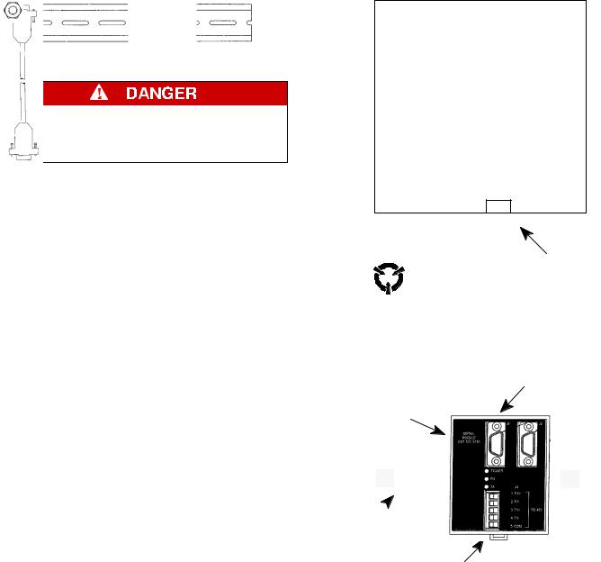
The Serial Module mounts on a DIN rail directly under the ATS controller. See Figures 1 and 2.
1.De–energize both Normal and Emergency sources that feed the ATS. Then open the enclosure door and check with a non–contact AC voltage detector.
2.Mount the DIN rail (supplied in the kit) onto two studs (on the door) below the controller.
3.Install the Serial Module onto the DIN rail by hooking the top of the module on the top of the DIN rail and rocking it downward until it snaps in place. If you need to remove the Serial Module, pull the release tab underneath.
Connections
A short serial cable connects the Serial Communication Module to the Controller. If a Power Manager is present, a long serial cable connects the Serial Communication Module to the Power Manager. Refer to wiring diagram provided. Wiring must be performed by an experienced licensed electrician in accordance with the National Electrical Code and all local codes.
1.Install the 10–inch serial cable (from the kit) between the ATS controller receptacle (J7 on 4000 & 7000 Series, J4 on Series 300) and the Serial Module receptacle J1.
2.If a Power Manager is present, connect the 4–foot serial cable between Power Manager receptacle J5 and the Serial Module receptacle J2* (see Figure 2).
*A 9–foot serial cable (629798–004) is required for G7ATB, G7ACTB, G7ADTB.
3.Prepare and connect the specified communication cable (Table A) to the Serial Module J4 terminal plug as listed in Table B and shown in Figure 3.
4.When daisy chaining multiple ATSs, the ATS the farthest distance from the controlling device must have a termination resistor. The Serial Module has a built–in termination resistor that can be connected by moving two DIP switches to ON (see Figure 4).
Group 1 or 5
ATS Controller
9–pin D connector
|
serial |
|
connector |
Touch ground first ! |
10–inch |
serial cable |
|
Electrostatic |
|
sensitive devices. |
|
|
serial |
|
connector |
Serial |
J1 |
|
|
Module |
|
DIN rail 
removable plug |
|
|
|||
with terminals |
|
|
|||
Figure 1. Serial Module mounted on DIN rail. |
|||||
Table A. Acceptable Communication Cable. |
|||||
|
|
|
|
|
|
Standard 80 degree C |
|
Plenum Rated |
|||
Cable |
|
|
|
|
Cable |
Belden 9842 or 9829 |
|
Belden 89729 or 82729 |
|||
Alpha 6202C or 6222C |
|
Alpha 58902 |
|||
Table B. Serial communication connections. |
|||||
|
|
|
|
|
|
Serial Module |
Function |
|
Description |
||
J4 terminals |
|
||||
|
|
|
|
|
|
5 |
|
COM |
|
shield |
|
3 |
|
TX+ |
|
twisted pair |
|
4 |
|
TX– |
|
||
|
|
|
|||
1 |
|
RX+ |
|
twisted pair |
|
2 |
|
RX– |
|
||
|
|
|
|||
1
 Loading...