


Operator’s
Manual
 Series 185 Automatic Transfer Switches
100 through 400 ampere sizes
DANGER is used in this manual to warn of high voltages capable of causing shock, burns, or death.
WARNING is used in this manual to warn of possible personal injury.
CAUTION is used in this manual to warn of possible equipment damage.
An experienced licensed electrician must install the ATS.
100–230 ampere sizes
Refer to the outline and wiring drawings provided with your ASCO Series 185 ATS for all installation details.
ASCO Series 185 Automatic Transfer Switches (ATSs) are Listed under Underwriter’s Laboratories Standard for Transfer Switch Equipment, UL–1008. They are intended for use only in optional standby systems in accordance with the National Electrical Code, NEC/NFPA 70, Article 702. This ATS is for use with 2–wire automatic start generators only.
Refer to Application Informaton 381339–292 to confirm that you have selected tha appropriate product for the intended installation.
This automatic transfer switch is intended for standby power applicatons in residential / light commercial use only.
This product is not intended for emergency or life–support systems.
If you have more stringent application requirements contact ASCO Power Technologies for other products suitable for critical applications.
Rating Label
Each automatic transfer switch contains a rating label to define the loads and fault circuit withstand / closing ratings. Refer to the label on the transfer switch for specific values.
Do not exceed the values on the rating label. Exceeding the rating can cause personal injury or serious equipment damage.
TABLE OF CONTENTS
page INSTALLATION . . . . . . . . . . . . . . . . . . . . . . . . . . 1 CONTROLLER . . . . . . . . . . . . . . . . . . . . . . . . 2–5 FUNCTIONAL TEST . . . . . . . . . . . . . . . . . . . . . . 6 SEQUENCE OF OPERATION . . . . . . . . . . . . . 7 TROUBLESHOOTING . . . . . . . . . . . . . . . . . . 8–9 INDEX . . . . . . . . . . . . . . . . . . . . . . . . . . . . . . . . . 10
50 Hanover Road, Florham Park, New Jersey 07932–1591 USA |
381333–319 A |
For sales or service call 1 800 800–2726 (ASCO) www.ascopower.com |
|
ASCO POWER TECHNOLOGIES CANADA PO Box 1238, 17 Airport Road, Brantford, Ontario, Canada N3T 5T3 telephone 519 758–8450, fax 519 758–0876, for service call 1 888 234–2726 (ASCO) www.asco.ca

Series 185
Nameplate |
Catalog Number Identification |
The Transfer Switch nameplate includes data for each specific ASCO Series 185 ATS. Use the ATS only within the limits shown on this nameplate.
A typical Catalog Number is shown below with its elements explained. The example is for a D–design, 2 pole, 200 A, 220–240 V, in a Type 1 indoor enclosure:
D 185 |
|
A |
|
2 |
|
200 |
|
F |
|
4 |
|
C |
Neutral |
|
Phase Poles |
|
Amperes |
|
Voltage |
|
|
Controller |
|
Enclosure |
A – standard |
|
2 – single Ø |
|
100 |
|
F 220---240 |
|
|
4 – standard |
|
C – Type 1 |
|
|
|
|
200 |
|
|
|
|
4X – if |
|
M – Type 3R |
|
|
|
|
230 |
|
|
|
|
accessories |
|
|
|
|
|
|
260 |
|
|
|
|
ordered |
|
|
|
|
|
|
|
|
|
|
|
|
|
|
|
|
|
|
400 |
|
|
|
|
|
|
|
|
|
|
|
|
|
|
|
|
|
|
|
|
|
|
|
|
|
|
|
|
|
|
|
clock battery |
cable spacers |
|
|
load power |
|
emergency |
|||||
|
|
|
(see INSTALLATION) |
connections |
|
||||||
|
|
|
|
power |
|||||||
|
|
|
|
|
|
|
|
|
|
|
|
|
|
|
|
|
|
|
|
|
|
|
connections |
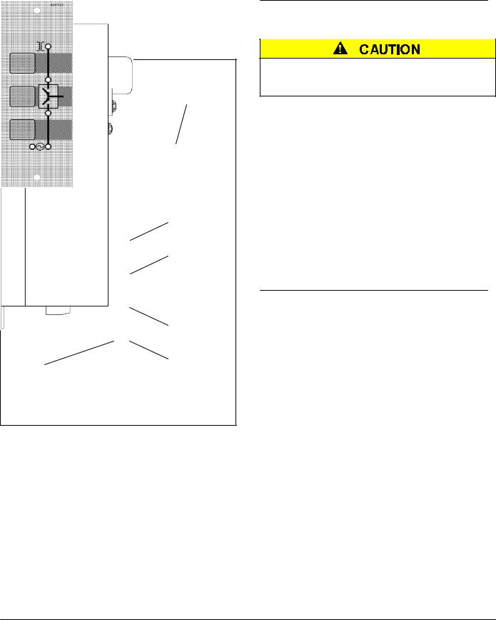
neutral connections
terminals for optional switch position contacts (shown installed)
Transfer
Switch
 ground connections
membrane |
generator |
Controller |
utility power |
|
controls |
||||
control |
harness plug |
connections |
||
|
connections |
|||
|
|
|
200 ampere size in typical enclosure with location of customer connections
381333–319 A
INSTALLATION |
Series 185 |
|
|
Installation of the ASCO Series 185 automatic transfer switch (ATS) must be performed by a licensed electrician. It must be installed according to the National Electrical Code (NEC) and all local electrical code requirements. Remove the enclosure cover and inspect the ATS for shipping damage. If damage is evident do not install the ATS.
1 --- Mounting
Refer to the enclosure outline drawing. Mount the ATS according to details and instructions shown on this diagram. Mount the ATS vertically to a rigid supporting structure. Level all mounting points by using flat washers behind the holes to avoid distortion of the enclosure.
MALFUNCTION or SHORTENED LIFE
Protect the ATS from construction grit and metal chips to prevent malfunction or shortened life.
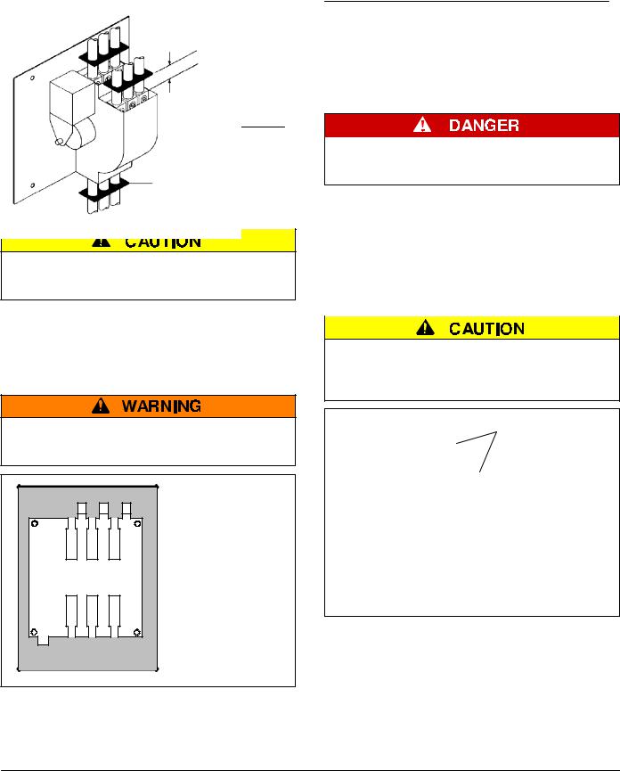
Transfer switches rated 260 and 400 amperes are mounted on an insulator backing piece (installed behind the transfer switch). If the transfer switch is removed from the enclosure and then reinstalled, this insulator must be placed behind the transfer switch. See Figure 1.
FLASH HAZARD – DAMAGE
Be sure that the insulator piece is installed behind the 260 and 400 ampere transfer switches.
Figure 1. Insulator for 260 and 400 A.
2 --- Electrical Power Connections
Refer to the wiring diagram. The ATS must be protected by suitably sized circuit breakers feeding the utility and generator source terminals. The rating of the circuit breakers must be based on the requirements of the National Electrical Code for its nameplate ampere and short circuit withstand ratings.
ELECTROCUTION HAZARD Turn off utility power and turn off the generator to prevent electrocution when wiring the transfer switch.
Cable Spacers for 200 and 230 A
Three cable spacers are included with 200 and 230 ampere transfer switches. Run the copper power cables through the cable spacers as shown in Figure 2. Position the cable spacers approximately 1½ inches from the terminal lugs.
CABLE LOOSENING DUE TO SHORT CIRCUIT Install three cable spacers 1 1/2 inches from the power terminals to prevent the cables from loosening during a short–short condition.
cable spacers
1 ½ inch approximate
use copper power cables only for 200 and 230 A
cable spacer
Figure 2. Cable spacers for 200 and 230 A.
1 |
381333–319 A |
Series 185 |
CONTROLLER |
|
|
The Group 4 digital Controller is used in ASCO Series 185 automatic transfer switches. It provides the sensing, timing, and control functions for the ATS. This micro– processor–based controller includes built–in control buttons and status lights for control of the ATS and generator.
clock battery cover
see page 3
|
|
Utility |
|
|
Acceptable |
Transfer |
|
Load on |
|
||
Test |
|
Utility light |
button |
|
|
Bypass |
|
|
|
|
|
Time Delay |
|
|
button |
|
|
Set |
|
Load on |
|
||
Exerciser |
|
|
button |
|
Generator |
|
|
light |
Automatic |
|
Generator |
Generator |
|
|
|
Acceptable |
|
Exerciser |
|
|
|
light |
|
light |
|
|
|
|
Figure 3. Front view of controller.
1 --- Push Buttons
On the front control display are three push buttons that control the operation of the generator and the ATS.
Before using the transfer test button, be sure that conditions are safe for running the generator and for load transfer.
Transfer Test
Use this button to test the system. This operation starts the generator and transfers the load. Be sure that conditions are safe to do this operation.
Bypass Time Delay
Use this button to cancel the active time delay or exercise period (stops the generator after cooldown).
Set Engine Exerciser
Use this button to set the automatic generator exerciser (page 3).
2 --- Indicator Lights
On the front control display are five lights that indicate the status of the sources and the ATS.
Utility Acceptable
This light indicates that the utility voltage is acceptable for connection to the load.
Generator Acceptable
This light indicates that the generator voltage is acceptable for connection to the load.
Load on Utility
This light indicates that the generator voltage is acceptable for connection to the load.
Load on Generator
This light indicates that the generator voltage is acceptable for connection to the load.
Automatic Generator Exerciser
When the utility is acceptable and the load is on the utility, this light flashes the number of days until the next exercise period. When it is off, no exerciser period is set. The light is also off when the generator is running.
381333–319 A |
2 |
 Loading...