


5081-P-FF

Model 5081-P-FF/FI
F
OUNDATION
®
Fieldbus Two-Wire pH/ORP
Transmitter
Instruction Sheet
PN 51A-5081P-FF-FI/rev.B
October 2007
ESSENTIAL INSTRUCTIONS
READ THIS PAGE BEFORE PROCEEDING!
Your purchase from Rosemount Analytical, Inc. has resulted in one of the finest instruments available for your
particular application. These instruments have been designed, and tested to meet many national and international standards. Experience indicates that its performance is directly related to the quality of the installation
and knowledge of the user in operating and maintaining the instrument. To ensure their continued operation to
the design specifications, personnel should read this manual thoroughly before proceeding with installation,
commissioning, operation, and maintenance of this instrument. If this equipment is used in a manner not specified by the manufacturer, the protection provided by it against hazards may be impaired.
• Failure to follow the proper instructions may cause any one of the following situations to occur: Loss of life;
personal injury; property damage; damage to this instrument; and warranty invalidation.
• Ensure that you have received the correct model and options from your purchase order. Verify that this manual covers your model and options. If not, call 1-800-854-8257 or 949-757-8500 to request correct manual.
• For clarification of instructions, contact your Rosemount representative.
• Follow all warnings, cautions, and instructions marked on and supplied with the product.
• Use only qualified personnel to install, operate, update, program and maintain the product.
• Educate your personnel in the proper installation, operation, and maintenance of the product.
• Install equipment as specified in the Installation section of this manual. Follow appropriate local and national
codes. Only connect the product to electrical and pressure sources specified in this manual.
• Use only factory documented components for repair. Tampering or unauthorized substitution of parts and
procedures can affect the performance and cause unsafe operation of your process.
• All equipment doors must be closed and protective covers must be in place unless qualified personnel are
performing maintenance.
• If this equipment is used in a manner not specified by the manufacturer, the protection provided by it against
hazards may be impaired.
For additional information, please refer to the Instruction Manuals CD shipped with this
product, or visit our website at www.emersonprocess.com/raihome/liquid/.
MODEL 5081-P-FF/FI SPECIFICATIONS
SPECIFICATIONS - GENERAL
Case: Cast aluminum containing less than 6% magnesium.
NEMA 4X (IP65), NEMA 7 (explosion-proof)
Epoxy-polyester paint, Neoprene O-ring seals
Dimensions: 6.3 in. x 6.9 in. x 6.4 in. (160 mm x 175 mm x 161
mm); diameter 6.1 in (155 mm)
Conduit Openings: 3/4 in. FNPT
Reference Impedance: Transmitter accepts high impedance
(i.e. glass) reference electrodes as well as low impedance
(i.e. silver-silver chloride) reference electrodes.
Response Time: Display reaches 95% of final reading within 10
seconds.
Temperature Sensors: The following RTDs can be used with
the Model 5081-P pH/ORP transmitter:
3 and 4 wire Pt 100 RTDs
3 and 4 wire Pt 1000 RTDs
Transmitter can also be used with two-wire RTDs.
Temperature Range: 5°F to 248°F (-15°C to 130°C)
Local Display: Two line LCD; first line shows process variable
(pH or ORP), second line shows temperature and output signal. When triggered, fault and warning messages alternate
with temperature and output readings.
Process variable: 7 segment LCD, 0.8 in. (20 mm) high
Temperature/output: 7 segment LCD, 0.3 in. (7 mm) high
Display board can be rotated 90 degrees clockwise or counterclockwise.
During calibration and programming, messages and prompts
appear in the temperature/output area.
Power Supply and Load Requirements:
A power supply volt-
age of 9-32 Vdc at 22 mA is required.
Security: User selected security code prevents accidental
changes to program settings.
Ambient Temperature: -4 to 149°F (-20 to 65°C)
Relative Humidity: 0 to 95% (with covers sealed)
Storage Temperature: -22 to 176°F (-30 to 80°C)
EMI/RFI: Meets the requirements of
EN-61326
Hazardous Area Classification:
Intrinsic Safety:
Class I, II, III, Div. 1
Groups A-G
T4 Tamb = 70°C
Exia Entity
Class I, Groups A-D
Class II, Groups E-G
Class III
T4 Tamb = 70°C
ATEX 0600 II 1 G
Baseefa02ATEX1284
EEx ia IIC T4
Tamb = -20°C to +65°C
Non-Incendive:
Class I, Div. 2, Groups A-D
Dust Ignition Proof
Class II & III, Div. 1, Groups E-G
NEMA 4X Enclosure
Class I, Div. 2, Groups A-D
Suitable for Class II, Div. 2, Groups E-G
T4 Tamb = 70°C
Explosion-Proof:
Class I, Div. 1, Groups B-D
Class II, Div. 1, Groups E-G
Class III, Div. 1
Class I, Groups B-D
Class II, Groups E-G
Class III
Tamb = 65°C max
SPECIFICATIONS - pH
pH Input Range: 0 to 14 pH
Temperature Input Range: 5°F to 248°F (-15°C to 130°C)
Accuracy at 25°C: ±0.01 pH
Repeatability at 25°C: ±0.01 pH
Resolution: 0.01 pH and 0.1°C or °F
Stability at 25°C: 0.25% per year
Diagnostics: The internal diagnostics can detect:
Calibration Error Low Temperature Error
High Temperature Error Sensor Failure
Line Failure CPU Failure
ROM Failure Input Warning
Glass Failure Glass Warning
Reference Failure Reference Warning
Once one of the above is diagnosed, the LCD will display a
message describing the failure/default detected.
Temperature Compensation: Automatic or manual between 5°F
to 248°F (-15°C to 130°C)
Solution Temperature Compensation: Transmitter will convert
pH measured at any temperature to the pH at 25°C.
Temperature coefficient is programmable between -0.044
pH/°C and 0.028 pH/°C
Calibration: Automatic two-point and manual two-point buffer
calibration. For automatic calibration, the transmitter recognizes NIST, DIN 19266 and 19267, JIS 8802, BSM, Merck,
and Ingold buffers.
SPECIFICATIONS - ORP
ORP Input Range: -1400 to 1400 mV
Temperature Input Range: 5°F to 248°F (-15°C to 130°C)
Output Scale Expansion: Continuously expandable between -
1400 and 1400 mV
Accuracy at 25°C: ±1 mV
Repeatability at 25°C: ±1 mV
Resolution: 1 mV and 0.1°C or °F
Stability at 25°C: 0.25% per year
2
Sira MC070112/00
3
MODEL 5081-P-FF/FI WIRING
SENSOR WIRING AND SET-UP
Wire sensor per Figure 1. Refer to the sensor instruction
manual for more details.
If your sensor has an integral preamplifier or you are using
a remote preamplifier, you will need to change the preamplifier location in the program menu. Please see Figure 14.
Select “trAnS” for integral preamplifier or “SnSr” for J-box
or sensor preamplifier.
WIRING THROUGH A JUNCTION BOX WITH
REMOTE PREAMPLIFIER
Wire sensor as shown in Figure 5. Refer to the sensor
instruction manual for more details.
WIRING THROUGH A JUNCTION BOX
Sensors with integral preamplifiers can be wired to the analyzer through a remote junction box (PN 23550-00). Wire
the extension cable and sensor cable point-to-point. Refer
to the sensor instruction manual for more details.
POWER WIRING
For general purpose areas, wire power as shown in
Figure 1. For hazardous areas, please see hazardous
area installation drawings.
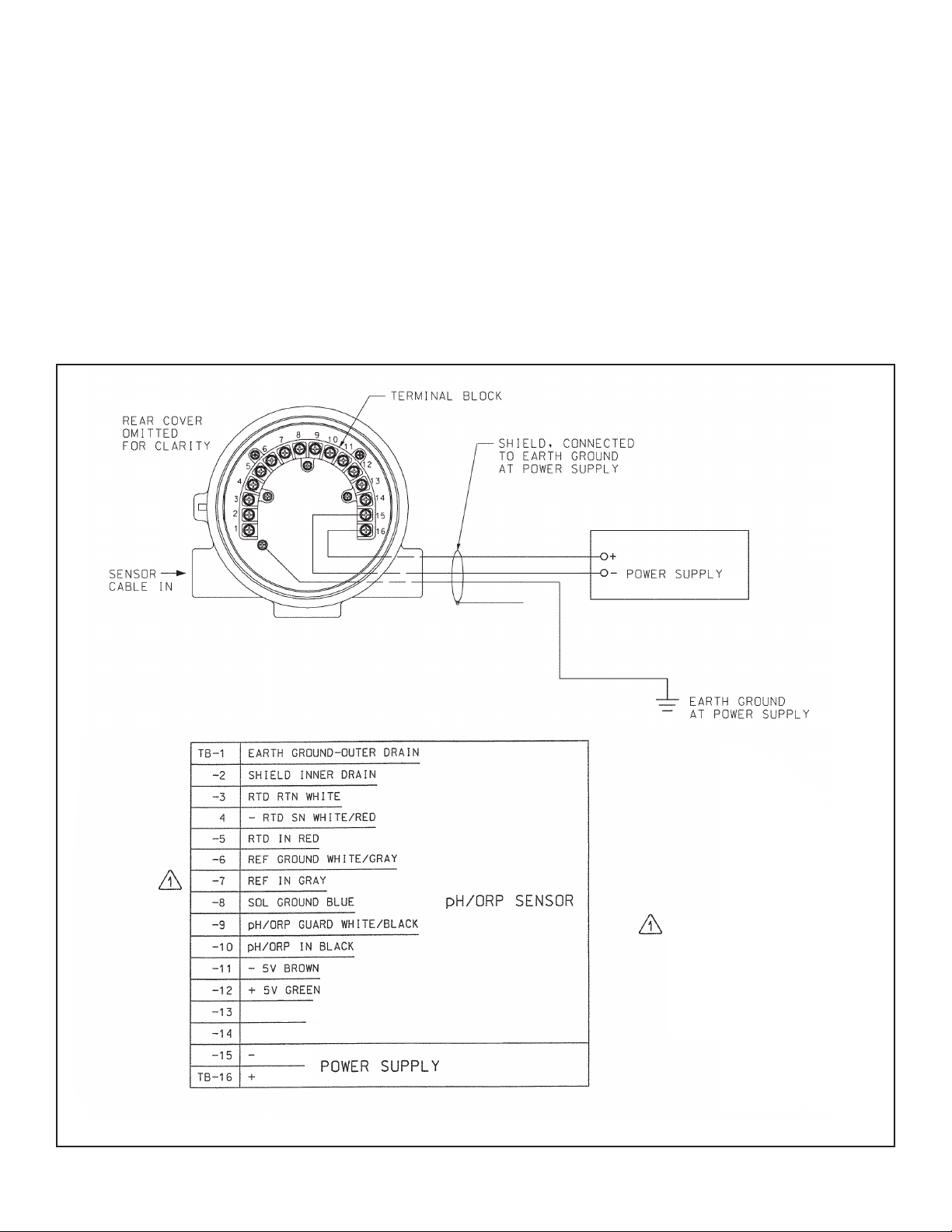
FIGURE 1. Model 5081-P-FF/FI Wiring Details
(9 - 32 VDC)
NOTE: REF wire covered with
sleeving. To prevent
depletion of KCL if
other wires touched,
remove sleeving
before wiring to TB-7.
4
MODEL 5081-P-FF/FI WIRING
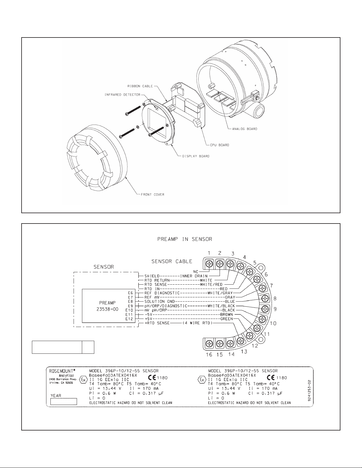
FIGURE 2. Exploded View of Model 5081-P-FF/FI
FIGURE 3. Wiring Diagram — Sensor with Preamplifier
DWG. NO. REV.
45081P30 A
5
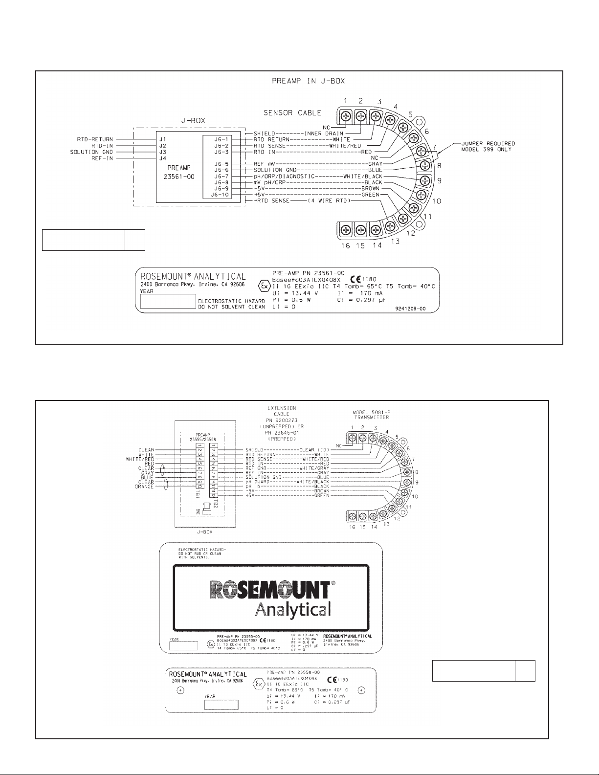
WIRING THROUGH A JUNCTION BOX WITH REMOTE PREAMPLIFIER
MODEL 5081-P-FF/FI WIRING
FIGURE 4. Wiring diagram — sensor Model 381+ with preamplifier
Wire sensor as shown in Figure 5. Refer to the sensor instruction manual for more details.
FIGURE 5. Wiring Through a Junction Box with Remote Preamplifier
DWG. NO. REV.
45081P28 A
DWG. NO. REV.
45081P29 A

MODEL 5081-P-FF/FI INSTALLATION
6
INSTALLATION
UNPACKING AND INSPECTION
Inspect the shipping container. If it is damaged, contact the
shipper immediately for instructions. Save the box. If there
is no apparent damage, unpack the container. Be sure all
items shown on the packing list are present. If items are
missing, notify Rosemount Analytical immediately.
ROTATING THE DISPLAY
The 5081-P-FF/FI display can be rotated 90° left or right.
Disengage the cover lock and remove the front cover.
Remove the three screws holding the PCB stack and gently lift the display board. Do not disengage the ribbon cable
between the display board and the CPU board. Rotate the
display. The black infrared sensor will be at the top of the
display.
INSTALLATION
See Figure 6.
1. Although the analyzer is suitable for outdoor use, do not
install it in direct sunlight or in areas of extreme temperatures.
2. Install the analyzer in an area where vibrations and electromagnetic and radio frequency interference are minimized or absent.
3. Keep the analyzer and sensor wiring at least one foot
from high voltage conductors. Be sure there is easy
access to the analyzer.
4. The conduit connections on the sides of the 5081-P
housing should be sealed to prevent moisture from
entering the enclosure.
5. The transmitter must not be mounted with both conduit
openings at the top.
MILLIMETER
INCH
FIGURE 6. Mounting Model 5081-P-FF/FI
7
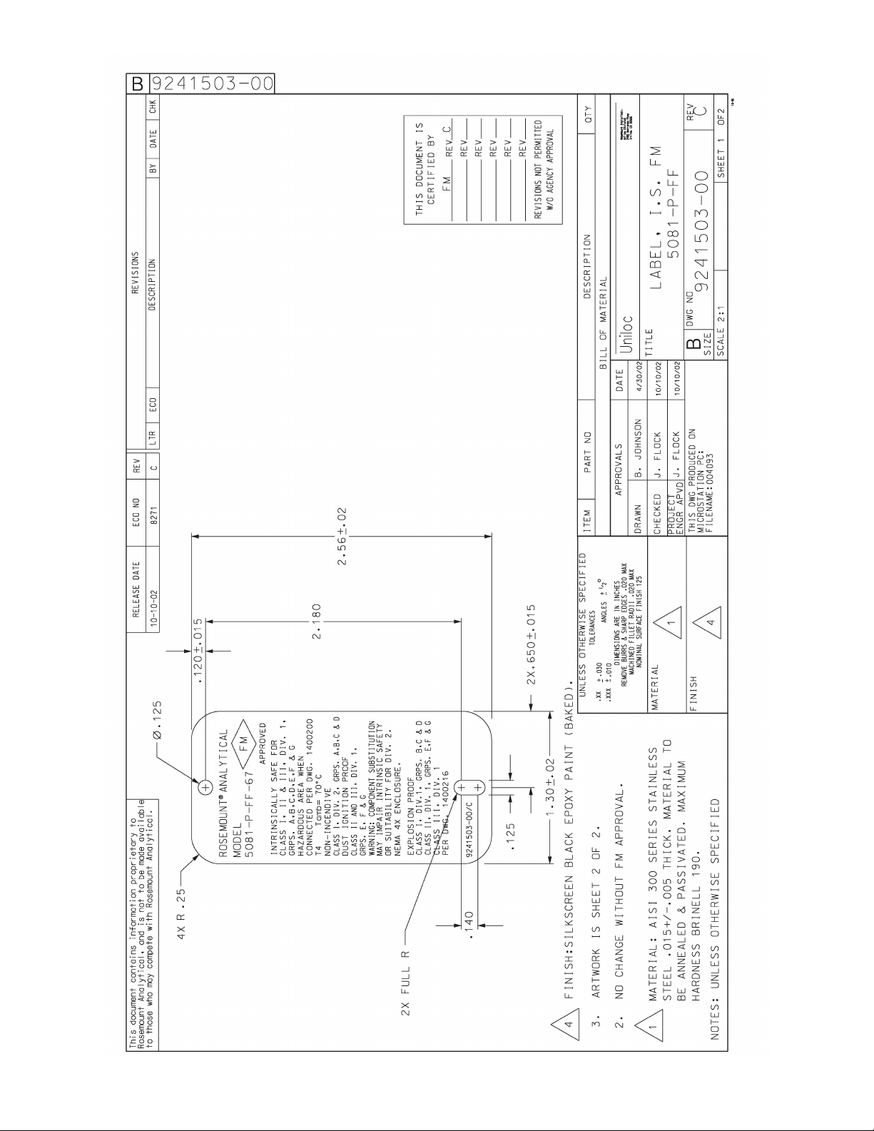
FIGURE 8. FM Intrinsically Safe Installation Label
8
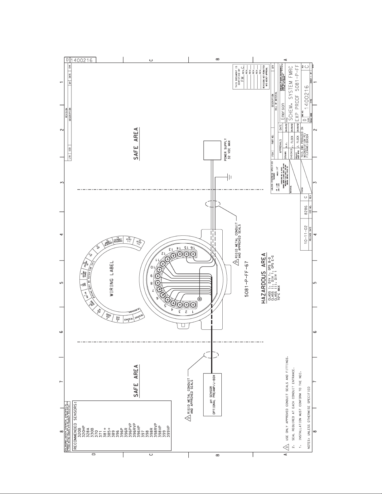
FIGURE 7. FMRC Explosion-Proof Installation
MODEL 5081-P-FF/FI HAZARDOUS AREA INSTALLATION
HAZARDOUS AREA INSTALLATION
9
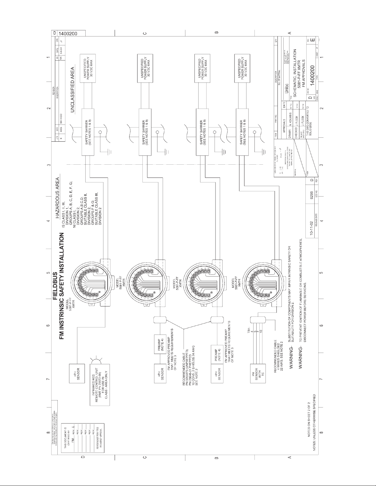
FIGURE 9. FM Intrinsically Safe Installation (1 of 2)
 Loading...