


 Loading...
Quick Start Guide
00825-0200-4840, Rev BA
December 2014
Rosemount Ultrasonic
3107 Level and 3108 Flow Transmitters

Quick Start Guide |
December 2014 |
|
|
©
 NOTICE
This installation guide provides basic guidelines for the Rosemount 3107 and Rosemount 3108. It does not provide instructions for detailed configuration, diagnostics,
maintenance, service, troubleshooting, or installations. Refer to the Rosemount 3107 and 3108 Reference Manual (Document Number 00809-0200-4840) for more instructions. Manuals are available electronically on www.rosemount.com.
Failure to follow these installation guidelines could result in death or serious injury
The Rosemount 3107 and Rosemount 3108 are ultrasonic transmitters. They must be installed, connected, commissioned, operated, and maintained by suitably qualified personnel only, observing any national and local requirements that may apply
Use the equipment only as specified. Failure to do so may impair the protection provided by the equipment
Explosions could result in death or serious injury
Installation of the transmitters in a hazardous environment must be in accordance with the appropriate local, national, and international standards, codes, and practices. Please review the Product Certifications section for any restrictions associated with a safe installation
Before connecting a Field Communicator in an explosive atmosphere, ensure the instruments are installed in accordance with intrinsically safe or non-incendive field wiring practices
Verify that the operating atmosphere of the transmitter is consistent with the appropriate hazardous locations certifications
External surface may be hot
Care must be taken to avoid possible burns
Process leaks could result in death or serious injury
Install and tighten process connectors before applying pressure
Do not attempt to loosen or remove process connectors while the transmitter is in service
Electrical shock could cause death or serious injury
Make sure that the transmitter is not powered when making connections
If the liquid level switch is installed in a high voltage environment and a fault condition or installation error occurs, high voltage may be present on leads and terminals
2
December 2014 |
Quick Start Guide |
Overview of the Rosemount 3107 and 3108
The Rosemount 3107 and 3108 are sealed 4–20 mA loop-powered liquid level transmitters, specifically designed for use in waste water and effluent treatment plant on aqueous applications.
These rugged UPVC transmitters are certified Intrinsically Safe for use in Zone 0 areas, and factory fitted with up to 165 ft. (50 m) of two-core cable for simple low cost installation in sumps, wet-wells and over open channel flow structures.
The transmitter may be mounted in a hazardous area if powered from a protected power supply. They can be connected directly to a plant control system, or used with a Rosemount 3490 Series Control Unit for programmable control functionality.
Theory of operation
Each transmitter is designed to be mounted above a liquid, and uses ultrasonic pulses to continuously measure the distance to the liquid surface. The microprocessor-controlled electronics calculates distance to the liquid level from the time delay between the transmitting and receiving of signals.
When programmed with the bottom reference of the application – usually the bottom of a tank – the transmitter will calculate the liquid depth (level), and output the level (Figure 1) as a 4–20 mA signal and a digital HART® signal.
The 3107 and the 3108 can also calculate contents (volume) or open channel flow, and then output the result as a 4–20 mA signal and a digital HART signal.
Programming is achieved by remote communication using HART.
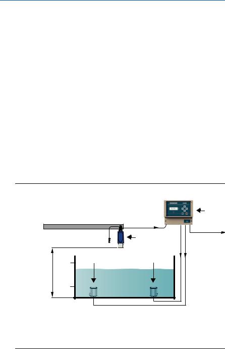
Figure 1. Typical application
|
|
|
B |
|
|
G |
|
|
|
A |
C |
|
|
D |
D |
20mA |
E |
E |
|
|
|
|
|
F |
|
|
|
4mA |
|
|
|
A. Rosemount 3108 Flow Transmitter |
E. Pump |
|
|
B. Rosemount 3490 Series Control Unit |
F. Transmitter Bottom Reference |
||
C. 4–20 mA signal output |
|
G. 4–20 mA and HART signal input |
|
D. Relay |
|
|
|
3
Quick Start Guide |
December 2014 |
|
|
Components of the transmitter
The transmitter has a housing containing advanced electronics to generate ultrasonic pulses, process the resultant signals, and provide a 4–20mA and HART output.
There is a factory-fitted cable for the signal output and connecting an external power supply. The 3108 has a factory-fitted Remote Temperature Sensor.
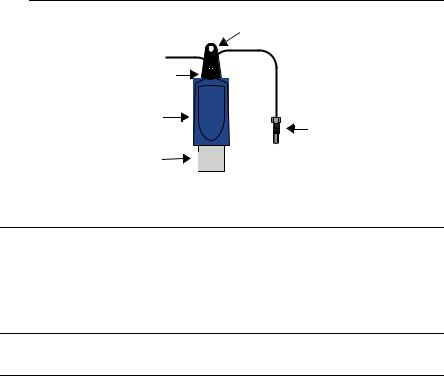
Figure 2. Transmitter components
A
|
B |
|
C |
|
D |
|
E |
|
D |
A. Mounting bracket |
D. UPVC wetted parts |
B. Two-core cable |
E. Remote temperature sensor (3108 only) |
C. 1-in. mounting thread |
|
Considerations before you install
Install the transmitter where it is protected from ultraviolet radiation to prevent long term degradation of the plastics used in its construction e.g. shrouded from direct sunlight.
Note
See also “Product Certifications” on page 21 for special conditions for safe use.
General
Installation must be carried out by suitably trained personnel in accordance with the applicable code of practice.
If the equipment is likely to come into contact with aggressive substances, it is the responsibility of the user to take suitable precautions that prevent it from being adversely affected, thus ensuring that the type of protection is not compromised.
Aggressive Substances are acidic liquids or gases that may attack metals or solvents that may affect polymeric materials.
Suitable Precautions are regular checks as part of routine inspections, or establishing, from the material's datasheet, that it is resistant to specific chemicals.
The equipment should only be cleaned with a damp cloth; do not use solvents.
4

December 2014 |
Quick Start Guide |
|
|
The transmitter is Double Insulated, and therefore Protective Earthing is not required. However, the cable screen should be connected (see Figure 9 on page 10).
Note that if the equipment is used in a manner not specified by the manufacturer, the protection afforded by the equipment may be impaired.
This transmitter is classified Type A in accordance with the European EMC directive 2004/108/EC. To ensure electro-magnetic compatibility, in any member state, it should not be installed in a residential area.
Note
It is not advisable to mount the transmitter in close proximity to a source of electrical noise such as a variable-speed drive, or other high-powered electrical device.
Environmental
The Rosemount 3107 and 3108 ultrasonic transmitters are Intrinsically Safe (IS) approved for hazardous area installations.
The 3107 is designed for open or closed tank installation. It is weatherproof and protected against the ingress of dust
The 3108 is designed for open channel flow measurement. It is weatherproof and protected against the ingress of dust
Avoid installing the 3107 and 3108 near heat sources
Figure 3. Environmental considerations
|
|
|
|
|
|
|
|
|
OK |
OK |
OK |
||||||
Installation
Mount the transmitter above the liquid using the 1-in. thread provided, but no closer than 13.8 in. (0,35 m) to the surface. The transmitter does not detect any liquid surface closer than 12 in. (0,3 m) to the transmitter face
The transmitter should be mounted vertically to ensure a good echo from the liquid surface. The beam half angle of the transmitter is 6 degrees (Figure 5 on page 7)
5

Quick Start Guide |
December 2014 |
|
|
Obstructions in the tank, or well, may generate echoes which can be confused with the real liquid surface echo. Obstructions within the beam angle generate strong false echoes. Wherever possible, the transmitter should be positioned to avoid false echoes.
To avoid detecting unwanted objects in the tank or well, it is advisable to maintain a distance of at least 1.3 in. from the center line of the transmitter for every foot (11 cm per meter) range to the obstruction. (See Figure 5 on page 7).
No false echoes are generated if the transmitter is located near the side of the tank or well and the wall is smooth and free of protrusions. However, there will still be a reduction in the echo size. It is recommended that the transmitter be mounted no closer than 12 in. (0,3 m) to the wall to avoid a large reduction in the echo size
If the transmitter is mounted in an enclosed tank with a domed top, avoid mounting the transmitter in the center of the tank roof because this could act as a parabolic reflector and create unwanted echoes
Avoid applications where heavy condensation could form on the transmitter face
If the transmitter is mounted in a stand-off or nozzle, the transmitter face should protrude at least 0.2 in. (5 mm) into the tank
If the transmitter is used in environments where direct sunlight can cause high surface temperatures on exposed instruments, a sun-shade is recommended
Mounting the transmitter above the liquid surface
A 1 in. thread is provided to mount the transmitter (Figure 4). The thread form is either BSPP (G1) or NPT, and is marked below the mounting thread.
Mounting bracket
The transmitter is supplied with a purpose made 316 Stainless Steel mounting bracket (Figure 4) which should be used to mount the transmitter over the liquid surface. The bracket is designed to fit over the threaded neck of the transmitter and is retained by a locknut
Use a chain or wire through the hole provided in the bracket, which is shaped to ensure that the transmitter will hang perpendicular to the liquid surface.
Never suspend the transmitter by the cable. Check that the material of the chain or wire is corrosion resistant to the liquids and any vapors present.
The bracket may be bolted to a suitable cross member above the liquid surface. Ensure the transmitter is perpendicular to the surface to maximise the return echo size.
Figure 4. Mounting bracket
A
A. 1-in. mounting thread
6
December 2014 |
Quick Start Guide |
|
|
|
|
Note
To help with alignment, the echo size (signal strength) can be indicated on the Rosemount 3490 Series Control Unit or a Field Communicator.
Flange mounting
The instrument (accessory) flanges supplied by Emerson are manufactured from PVC and are a full face design. Care must be taken when installing to a raised face mating flange on the tank or vessel to prevent distortion of the PVC flange by over-tightening the bolts. See Product Data Sheet 00813-0200-4840 for a list of all accessories and their part numbers.
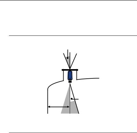
Figure 5. Flange mounting
A
B
C
A.Transmitter is mounted vertically (maximum deviation of 3°).
B.6° beam half angle.
C.1.3 in./ft. (11 cm/m). Minimum of 12 in. (0.3 m).
Mounting from a conduit
The 3107 and the 3108 can be mounted from a conduit using the optional adaptor accessory. See Product Data Sheet 00813-0200-4840 for a list of all accessories and their part numbers.
7
Quick Start Guide |
December 2014 |
|
|
Open channel flow installations
Mount an ultrasonic transmitter over an area of clear liquid. Avoid mounting the transmitter directly over any inlet stream. Never suspend the transmitter by the cable.
The positioning is critical, and should be the correct distance upstream from the flow structure as stated in the relevant standard for your country. For example, in the ISO standards, the distance should be four to five times the maximum height of the water (Hmax) for a thin plate weir, or three to four times Hmax for a flume. For optimum accuracy, position the transmitter’s front face at a height equal to the sum of the maximum flow depth plus the transmitter deadband of 12.2 in. (300 mm) plus an extra 2 in. (50 mm).
It is important that the bottom reference of the transmitter should be related to the datum of the primary measuring device (Figure 7).
When setting the bottom reference on a ‘V’- notch weir, it is important the true invert is used (Figure 8 on page 9) and not the meniscus level.
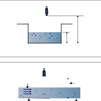
Figure 6. Choosing the height position above a flow
A
C
B
A.Transmitter front face
B.Hmax
C.Transmitter bottom reference = Hmax + 12.2 in. (300 mm) + 2 in. (50 mm)
Figure 7. Bottom reference of a flume or weir
D |
|
|
|
|
|
A |
|
|
|
|
|
||
|
|
|
|
|
||
|
|
|
|
|
|
|
|
|
|
|
|
|
|
|
|
|
|
C |
B |
||
A. Transmitter bottom reference |
C. Approach channel |
||
B. Primary element (e.g. flume, weir) invert |
D. Flow |
||
|
|
|
|
8
December 2014 |
Quick Start Guide |
|
|
|
|
Note
The transmitter should be free from a situation where it is likely to 'drown' (refer to the relevant standard for further information)
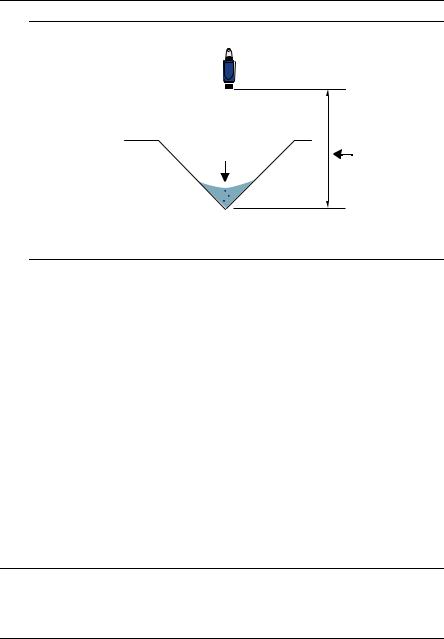
Figure 8. Bottom reference of a ‘V’ notch weir
B |
A |
A.Transmitter bottom reference (i.e. true invert)
B.Meniscus level
The Rosemount 3108 transmitter has a factory fitted remote temperature sensor. The temperature sensor is enclosed in a M8 x 1.5 threaded stainless steel body, and can be installed in a suitable plastic conduit box and clamped in place using a suitable compression type cable gland.
Open weir chamber
Mount the remote temperature sensor so that it is representative of the mean air temperature in the chamber and is in a shaded area away from direct sunlight and solar radiation.
Enclosed or partially covered flume chamber
Mount the remote temperature sensor in the approach channel, in a shaded area away from direct sunlight and solar radiation. The temperature sensor should be positioned in the weir chamber or flume approach channel so the average air temperature can be accurately measured. The temperature sensor must be protected at all times from direct sunlight and any radiated heat.
In extreme high temperatures, for the best accuracy and stability of level measurement reading, the transmitter should be shrouded to prevent the incidence of direct sunlight and solar radiation. If the flow structure permits, mount the transmitter within the flow channel or chamber.
Note
For some installations, the use of a calibration device is mandatory. Emerson offers the Rosemount Head Verification Device (HVD) for this purpose.
See Product Data Sheet 00813-0200-4840 for more information.
9
Loading...