


 Loading...
Quick Installation Guide
00825-0100-4801, Rev KB
December 2010
Rosemount 3051S
Rosemount 3051S Series Pressure Transmitter with HART® Protocol
Rosemount 3051SF Series Flowmeter Transmitter with HART® Protocol
Start
Step 1: Mount the Transmitter
Step 2: Consider Housing Rotation
Step 3: Set Switches and Jumpers
Step 4: Connect Wiring and Power Up
Step 5: Verify Configuration
Step 6: Trim the Transmitter
Safety Instrumented Systems
Product Certifications
End
¢00825-0100-4801J¤
www.rosemount.com

Quick Installation Guide
Rosemount 3051S
00825-0100-4801, Rev KB
December 2010
© 2010 Rosemount Inc. All rights reserved. All marks property of owner.
Rosemount and the Rosemount logotype are registered trademarks of Rosemount Inc.
Rosemount Inc. |
Emerson Process Management |
8200 Market Boulevard |
GmbH & Co. OHG |
Chanhassen, MN USA 55317 |
Argelsrieder Feld 3 |
T (US) (800) 999-9307 |
82234 Wessling |
T (Intnl) (952) 906-8888 |
Germany |
F (952) 949-7001 |
T 49 (8153) 9390, F49 (8153) 939172 |
Emerson Process Management |
Beijing Rosemount Far East Instrument Co., |
|
Asia Pacific Private Limited |
Limited |
|
1 Pandan Crescent |
No. 6 North Street, Hepingli, Dong Cheng District |
|
Singapore 128461 |
Beijing 100013, China |
|
T (65) 6777 |
8211 |
T (86) (10) 6428 2233 |
F (65) 6777 |
0947/65 6777 0743 |
F (86) (10) 6422 8586 |
IMPORTANT NOTICE
This installation guide provides basic guidelines for Rosemount 3051S transmitters (reference manual document number 00809-0100-4801). It also provides the basic electronics guidelines for the 3051SFA (reference manual document number 00809-0100-4809), 3051SFC (reference manual document number 00809-0100-4810), and 3051SFP (reference manual document number 00809-0100-4686). It does not provide instructions for diagnostics, maintenance, service, or troubleshooting. This document is also available electronically on www.rosemount.com.


 WARNING
Explosions could result in death or serious injury:
Installation of this transmitter in an explosive environment must be in accordance with the appropriate local, national, and international standards, codes, and practices. Please review the approvals section of the 3051S reference manual for any restrictions associated with a safe installation.
•Before connecting a Field Communicator in an explosive atmosphere, ensure the instruments in the loop are installed in accordance with intrinsically safe or non-incendive field wiring practices.
•In an Explosion-Proof/Flameproof installation, do not remove the transmitter covers when power is applied to the unit.
Process leaks may cause harm or result in death.
• Install and tighten process connectors before applying pressure.
Electrical shock can result in death or serious injury.
•Avoid contact with the leads and terminals. High voltage that may be present on leads can cause electrical shock.
Conduit/Cable Entries
•Unless marked, the conduit/cable entries in the transmitter housing use a 1/2-14 NPT thread form. Only use plugs, adapters, glands, or conduit with a compatible thread form when closing these entries.
2
Quick Installation Guide
00825-0100-4801, Rev KB
December 2010
Rosemount 3051S
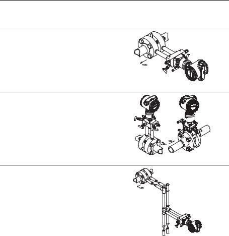
STEP 1: MOUNT THE TRANSMITTER
Liquid Flow Applications
1.Place taps to the side of the line.
2.Mount beside or below the taps.
3.Mount the transmitter so that the drain/vent valves are oriented upward.
Gas Flow Applications
1.Place taps in the top or side of the line.
2.Mount beside or above the taps.
Steam Flow Applications
1.Place taps to the side of the line.
2.Mount beside or below the taps.
3.Fill impulse lines with water.
3
Quick Installation Guide
Rosemount 3051S
00825-0100-4801, Rev KB
December 2010
STEP 1 CONTINUED...
|
|
|
|
|
|
|
|
|
|
|
|
|
|
|
|
|
|
|
|
|
|
|
|
|
|
|
|
|
|
|
|
|
|
|
|
|
|
|
|
|
|
|
|
|
|
|
|
|
|
|
|
|
|
|
|
|
|
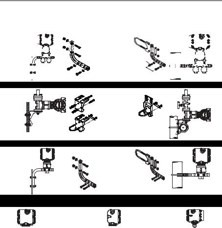
Panel Mount |
|
|
|
|
|
|
|
|
Pipe Mount |
||||||||||||||||||||||||||||||||
|
|
|
|
|
|
|
|
|
|
|
|
|
|
|
|
|
|
|
Coplanar™ Flange |
||||||||||||||||||||||||||||||
|
|
|
|
|
|
|
|
|
|
|
|
|
|
|
|
|
|
|
|
|
|
|
|
|
|
|
|
|
|
|
|
|
|
|
|
|
|
|
|
|
|
|
|
|
|
|
|
|
|
|
|
|
|
|
|
|
|
|
|
|
|
|
|
|
|
|
|
|
|
|
|
|
|
|
|
|
|
|
|
|
|
|
|
|
|
|
|
|
|
|
|
|
|
|
|
|
|
|
|
|
|
|
|
|
|
|
|
|
|
|
|
|
|
|
|
|
|
|
|
|
|
|
|
|
|
|
|
|
|
|
|
|
|
|
|
|
|
|
|
|
|
|
|
|
|
|
|
|
|
|
|
|
|
|
|
|
|
|
|
|
|
|
|
|
|
|
|
|
|
|
|
|
|
|
|
|
|
|
|
|
|
|
|
|
|
|
|
|
|
|
|
|
|
|
|
|
|
|
|
|
|
|
|
|
|
|
|
|
|
|
|
|
|
|
|
|
|
|
|
|
|
|
|
|
|
|
|
|
|
|
|
|
|
|
|
|
|
|
|
|
|
|
|
|
|
|
|
|
|
Traditional Flange
In-line
PlantWeb™ |
Housings |
|
Junction Box |
Remote Mount Display |
4
Quick Installation Guide
00825-0100-4801, Rev KB
December 2010
Rosemount 3051S
STEP 1 CONTINUED...
Bolting Considerations
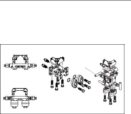
If the transmitter installation requires assembly of the process flanges, manifolds, or flange adapters, follow these assembly guidelines to ensure a tight seal for optimal performance characteristics of the transmitters. Use only bolts supplied with the transmitter or sold by Emerson as spare parts. Figure 1 illustrates common transmitter assemblies with the bolt length required for proper transmitter assembly.
Figure 1. Common Transmitter Assemblies
A. Transmitter with |
C. Transmitter with Traditional |
D. Transmitter with |
||
Flange and Optional Flange |
Coplanar Flange and |
|||
Coplanar Flange |
||||
Adapters |
|
Optional Manifold and |
||
|
|
|||
|
|
|
Flange Adapters |
|
|
|
4 x 2.25-in. (57 mm) |
||
4 x 1.75-in. (44 mm) |
|
|
|
|
B. Transmitter with Coplanar |
|
|
|
|
Flange and Optional |
|
|
|
|
Flange Adapters |
|
|
|
|
|
4 x 1.75-in. (44 mm) |
4 x 1.50-in. (38 mm) |
||
|
|
|||
|
|
|
4 x 1.75-in. (44 mm) |
|
4 x 2.88-in. (73 mm) |
|
|
|
|
Bolts are typically carbon steel or stainless steel. Confirm the material by viewing the markings on the head of the bolt and referencing Figure 2. If bolt material is not shown in Figure 2, contact the local Emerson Process Management representative for more information.
Use the following bolt installation procedure:
1.Carbon steel bolts do not require lubrication and the stainless steel bolts are coated with a lubricant to ease installation. However, no additional lubricant should be applied when installing either type of bolt.
2.Finger-tighten the bolts.
3.Torque the bolts to the initial torque value using a crossing pattern. See Figure 2 for initial torque value.
4.Torque the bolts to the final torque value using the same crossing pattern. See Figure 2 for final torque value.
5.Verify that the flange bolts are protruding through the isolator plate before applying pressure.
5

Quick Installation Guide
Rosemount 3051S
00825-0100-4801, Rev KB
December 2010
STEP 1 CONTINUED...
Figure 2. Torque values for the flange and flange adapter bolts |
|
||||||||
Bolt Material |
Head Markings |
|
|
|
Initial Torque |
Final Torque |
|||
Carbon Steel (CS) |
|
|
|
B7M |
|
|
|
300 in.-lbs. |
650 in.-lbs. |
|
|
|
|
|
|
||||
Stainless Steel (SST) |
|
|
|
|
|
|
150 in.-lbs. |
300 in.-lbs. |
|
|
B8M |
|
|
|
|||||
|
|
|
|
||||||
316 |
|
|
|
|
|
|
|||
|
|
|
|
|
|
||||
|
|
|
|
|
316 |
|
|
||
316 |
|
STM |
SW |
|
|||||
R |
316 |
|
316 |
|
|
||||
|
|
|
|
|
|
|
|
|
|
O-rings with Flange Adapters


 WARNING
Failure to install proper flange adapter O-rings may cause process leaks, which can result in death or serious injury. The two flange adapters are distinguished by unique O-ring grooves. Only use the O-ring that is designed for its specific flange adapter, as shown below.
Rosemount 3051S / 3051 / 2051 / 3095 |
Flange Adapter |
O-ring |
PTFE Based |
Elastomer |
Rosemount 1151 |
Flange Adapter |
O-ring |
PTFE |
Elastomer |
Whenever the flanges or adapters are removed, visually inspect the o-rings. Replace them if there are any signs of damage, such as nicks or cuts. If you replace the o-rings, re-torque the flange bolts and alignment screws after installation to compensate for seating of the PTFE o-ring.
6

Quick Installation Guide
00825-0100-4801, Rev KB
December 2010
Rosemount 3051S
STEP 1 CONTINUED...
Inline Gage Transmitter Orientation
The low side pressure port (atmospheric reference) on the inline gage transmitter is located under the sensor module neck label. (See Figure 3.)
Keep the vent path free of any obstruction, including but not limited to paint, dust, and lubrication by mounting the transmitter so that any contaminants can drain away.
Figure 3. Inline Gage Transmitter
Low side pressure port (under neck label)
STEP 2: CONSIDER HOUSING ROTATION
To improve field access to wiring or to better view the optional LCD display:
1.Loosen the housing rotation set screw.
2.First rotate the housing clockwise to the desired location. If the desired location cannot be achieved due to thread limit, rotate the housing counter clockwise to the desired location (up to 360° from thread limit).
3.Retighten the housing rotation set screw.
Figure 4. Transmitter Housing
Set Screw
PlantWeb |
Junction Box |
Housing Rotation Set
Screw (3/32-inch)
STEP 3: SET SWITCHES AND JUMPERS
If alarm and security adjustment option is not installed, the transmitter will operate normally with the default alarm condition alarm high and the security off.
Figure 5. Transmitter Switch and Jumper Configuration
PlantWeb
Meter/
Adjustment
Module
Security Alarm
Slide the security and alarm switches into the preferred position by using a small screwdriver. (An LCD display or an adjustment module must be in place to activate the switches.)
Junction Box
Security Alarm
Pull the jumpers out and rotate 90° into desired position to set the security and alarm.
7
Quick Installation Guide
Rosemount 3051S
00825-0100-4801, Rev KB
December 2010
STEP 4: CONNECT WIRING AND POWER UP
Use the following steps to wire the transmitter:
1.Remove the housing cover labeled “Field Terminals.”
2.Connect the positive lead to the “+” terminal, and the negative lead to the “–” terminal.
NOTE
Do not connect the power across the test terminals. Power could damage the test diode in the test connection. Twisted pairs yield best results. For single compartment housing (Junction Box housing), shielded signal wiring should be used in high EMI/RFI environments. Use 24 AWG to 14 AWG wire and do not exceed 5,000 feet (1500 meters).
3.Plug and seal the unused conduit connection.
4.If applicable, install wiring with a drip loop. Arrange the drip loop so the bottom is lower than the conduit connections and the transmitter housing.
5.Replace the housing cover.
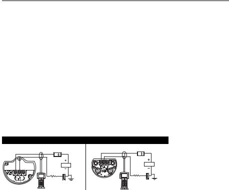
The figures below show the wiring connections necessary to power a 3051S and enable communications with a hand-held Field Communicator.
Figure 6. Transmitter Wiring |
|
PlantWeb Housing Wiring |
Junction Box Housing Wiring |
RL 250 |
RL 250 |
Power |
Power |
Supply |
Supply |
NOTE
Installation of the transient protection terminal block does not provide transient protection unless the 3051S case is properly grounded.
8
Quick Installation Guide
00825-0100-4801, Rev KB
December 2010
Rosemount 3051S
STEP 4 CONTINUED...
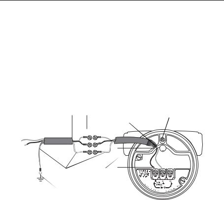
Signal Wiring Grounding
Do not run signal wiring in conduit or open trays with power wiring, or near heavy electrical equipment. Grounding terminations are provided on the sensor module and inside the Terminal Compartment. These grounds are used when transient protect terminal blocks are installed or to fulfill local regulations. See Step 2 below for more information on how the cable shield should be grounded.
1.Remove the Field Terminals housing cover.
2.Connect the wiring pair and ground as indicated in Figure 7. a. The cable shield should:
•Be trimmed close and insulated from touching the transmitter housing.
•Continuously connect to the termination point.
•Be connected to a good earth ground at the power supply end.
Figure 7. Wiring
Minimize |
|
|
|
|
|
Ground for |
|
Distance |
Trim shield and |
|
|||||
|
Transient |
||||||
|
|
|
|
insulate |
|
Protection |
|
|
|
|
|
|
|
|
|
|
|
|
|
|
|
|
|
|
|
|
|
|
|
|
|
|
|
|
|
|
|
|
|
|
|
|
|
|
|
|
|
|
|
|
|
|
|
|
|
|
|
|
|
|
|
|
|
Insulate |
Minimize |
Shield |
Distance |
 Connect Shield Back to the
Power Supply Ground
3.Replace the housing cover. It is recommended that the cover be tightened until there is no gap between the cover and the housing.
4.Plug and seal unused conduit connections.
9

Quick Installation Guide
Rosemount 3051S
00825-0100-4801, Rev KB
December 2010
STEP 4 CONTINUED...
Remote Display Wiring and Power Up
The Remote Mount Display and Interface system consists of a local transmitter and a remote mount LCD display assembly. The local 3051S transmitter assembly includes a Junction Box housing with a three position terminal block integrally mounted to a sensor module. The remote mount LCD display assembly consists of a dual compartment PlantWeb housing with a seven position terminal block. See Figure 8 on page 11 for complete wiring instructions. The following is a list of necessary information specific to the Remote Mount Display system:
•Each terminal block is unique for the remote display system.
•A 316 SST housing adapter is permanently secured to the remote mount LCD display PlantWeb housing, providing an external ground and a means for field mounting with the provided mounting bracket.
•A cable is required for wiring between the transmitter and remote mount LCD display. The cable length is limited to 100 ft.
•50 ft. (option M8) or 100 ft. (option M9) cable is provided for wiring between the transmitter and remote mount LCD display. Option M7 does not include cable; see recommended specifications below:
Cable type: Recommend Belden 3084A DeviceNet cable or Belden 123084A Armored DeviceNet cable. Other comparable cable may be used as long as it has independent dual twisted shielded pair wires with an outer shield. The Power wires must be 22 AWG minimum and the CAN communication wires must be 24 AWG minimum.
Cable length: Up to 100 feet depending upon cable capacitance.
Cable capacitance: The capacitance from the CAN communications line to the CAN return line as wired must be less than 5000 picofarads total. This allows up to 50 picofarads per foot for a 100 foot cable.
10
Quick Installation Guide
00825-0100-4801, Rev KB
December 2010
Rosemount 3051S
STEP 4 CONTINUED...
Intrinsic Safety Consideration: The transmitter assembly with remote display has been approved with Belden 3084A DeviceNet cable. Alternate cable may be used as long as the transmitter with remote display and cable is configured according to the installation control drawing or certificate. Refer to appropriate approval certificate or control drawing in Appendix B of the 3051S reference manual for remote cable IS requirements.
IMPORTANT
Do not apply power to the remote communications terminal. Follow wiring instructions carefully to prevent damage to system components.
Figure 8. Remote Mount Display wiring diagram
Junction Box Housing |
Remote Mount Display |
(white) 24 AWG |
|
(blue) 24 AWG |
|
(black) 22 AWG |
|
(red) 22 AWG |
|
|
4-20 mA |
11
Loading...