


1F97-1277
Big Blue Touchscreen Thermostat with
CAUTION
!
Automatic Heat/Cool Changeover Option
Installation and Operating Instructions for Model:
Save these instructions for future use!
FAILURE TO READ AND FOLLOW ALL INSTRUCTIONS
CAREFULLY BEFORE INSTALLING OR OPERATING THIS
CONTROL COULD CAUSE PERSONAL INJURY AND/OR
PROPERTY DAMAGE.
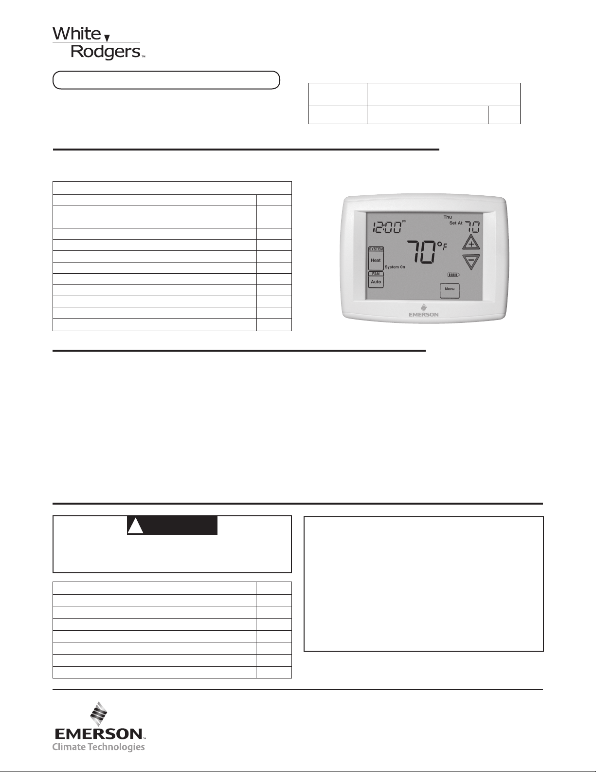
Model Programming Choices
1F97-1277
Non-Programmable 5+1+1 Day 7 Day
APPLICATIONS
THERMOSTAT APPLICATION GUIDE
Description
Heat Pump (No Aux. or Emergency Heat) Yes
Heat Pump (with Aux. or Emergency Heat) Yes
Systems with up to 3 Stages Heat, 2 Stages Cool No
Heat Only Systems Yes
Millivolt Heat Only Systems – Floor or Wall Furnaces Yes
Cool Only Systems Ye s
Gas or Oil Heat Yes
Electric Furnace Yes
Hydronic (Hot Water) Zone Heat – 2 Wires Ye s
Hydronic (Hot Water) Zone Heat – 3 Wires Ye s
Wired Remote Temperature Sensor (Indoor/Outdoor) Yes
Dual Fuel Feature (Heat Pump Mode) Yes
1F97-1277 Touchscreen Thermostat
SPECIFICATIONS
Electrical Rating:
Battery Power.......................... mV to 30 VAC, NEC Class II, 50/60 Hz or DC
Input-Hardwire ......................... 20 to 30 VAC
Terminal Load ............................. 1.5A per terminal, 2.5A maximum all terminals combined
Setpoint Range ............................ 45 to 99°F (7 to 37°C)
Differential (Single Stage) .................... Heat 0.6°F; Cool 1.2°F
Differential (Multi-Stage) ..................... Heat 0.6°F; Cool 1.2°F
Differential (Heat Pump) ..................... Heat 1.2°F; Cool 1.5°F
Operating Ambient.......................... 32°F to +105°F (0 to +41°C)
Operating Humidity ......................... 90% non-condensing max.
Shipping Temperature Range ................. -4 to +150°F (-20 to +65°C)
Dimensions Thermostat...................... 4-9/16"H x 5-13/16"W x 1-3/16"D
To prevent electrical shock and/or equipment damage,
disconnect electric power to system at main fuse or
circuit breaker box until installation is complete.
Index Page
Installation 2
Wiring Connections 2
Thermostat Quick Reference 4
Installer Conguration Menu 5
Operating Your Thermostat 8
Programming 9
Troubleshooting 12
www.white-rodgers.com
www.emersonclimate.com
ATTENTION: MERCURY NOTICE
This product does not contain mercury. However, this
product may replace a product that contains mercury.
Mercury and products containing mercury must not be
discarded in household trash. Do not touch any spilled
mercury. Wearing non-absorbent gloves, clean up any
spilled mercury and place in a sealed container. For proper
disposal of a product containing mercury or a sealed
container of spilled mercury, place it in a suitable shipping
container. Refer to www.thermostat-recycle.org for
location to send the product containing mercury.
PART NO. 37-7388A
1241
2 "AA" Batteries
INSTALLATION
Mounting
Hole
Mounting
Hole
Place Level
across
Mounting Tabs
(for appearance only)
Place Level
across
Mounting Tabs
(for appearance only)
+
S
-
W/E
6
L
WARNING
!
Thermostat installation and all components of the
control system shall conform to Class II circuits per
the NEC code.
Remove Old Thermostat
A standard heat/cool thermostat consists of three basic parts:
1. The cover, which may be either a snap-on or hinge type.
2. The base, which is removed by loosening all captive
screws.
3. The switching subbase, which is removed by unscrewing
the mounting screws that hold it on the wall or adapter
plate. Before removing wires from old thermostat,
label each wire with the terminal designation from
which it was attached. Disconnect the wires from the old
thermostat one at a time. Do not let wires fall back into
the wall.
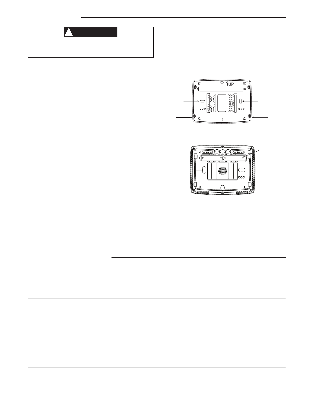
Battery Location
2 "AA" alkaline batteries are included in the thermostat at
the factory with a battery tag to prevent power drainage.
Remove the battery tag to engage the batteries.
To replace batteries, set system to OFF, remove thermostat
from wall and install the batteries in the rear along the top of
the thermostat (see Figure 1).
Figure 1 – Thermostat Base Multi-Stage 1F97-1277
Installing New Thermostat
1. Pull the thermostat body off the thermostat base. Forcing
or prying on the thermostat will cause damage to the unit.
2. Place base over hole in wall and mark mounting hole
locations on wall using base as a template.
3. Move base out of the way. Drill mounting holes. If you
are using existing mounting holes and the holes drilled
are too large and do not allow you to tighten base snugly,
use plastic screw anchors to secure the base.
4. Fasten base snugly to wall using mounting holes shown
in Figure 1 and two mounting screws. Leveling is for
appearance only and will not affect thermostat operation.
5. Connect wires to terminal block on base using appropriate
wiring schematic (see diagrams on next page).
6. Push excess wire into wall and plug hole with a re resistant material (such as berglass insulation) to prevent
drafts from affecting thermostat operation.
7. Carefully line the thermostat up with the base and snap
into place.
WIRING CONNECTIONS
Refer to equipment manufacturers' instructions for specic
system wiring information. After wiring, see CONFIGURA-
TION section for proper thermostat conguration.
Rear view of thermostat
For wiring diagrams, see next page.
Wiring diagrams shown are for typical systems and describe
the thermostat terminal functions.
TERMINAL DESIGNATION DESCRIPTIONS
Terminal Designation Description
B ...................Changeover valve for heat pump energized constantly in heating
O ...................Changeover valve for heat pump energized constantly in cooling
Y ...................Compressor Relay
G ...................Fan Relay
RC...................Power for Cooling
RH...................Power for Heating
C ...................Common wire from secondary side of cooling
L ...................For Call for Service indicator for systems with diagnostic connection
6 ...................Powered closed connection for 3-wire zone valve
W ...................Heat Relay
-....................Common (DC) for wired remote temperature sensor
S ...................Frequency signal from remote temperature sensor
+ ...................Power (DC) to remote temperature sensor
2
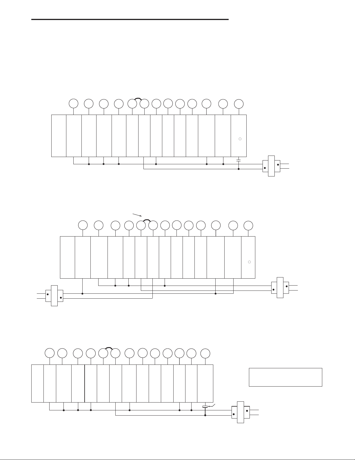
WIRING CONNECTIONS
To Remote Te mperature Sensor
HEATING
To Remote Temperature Sensor
Single Stage Connections
Refer to equipment manufacturers' instructions for specic system
wiring information.
This thermostat is designed to operate a single-transformer or twotransformer system.
You can congure the thermostat for use with the following systems:
Single Stage System with Single Transformer
To Remote Te mperature Sensor
Jumper
B
120VAC
TRANSFORMER
System
Single
Stage
(SS)
CLASS II
Energized
in Heat
or Off
Mode
System
Single
Stage
(SS)
NEUTRAL
24VAC
HOT
Energized in
Cool
Mode
B
Energized
in Heat,
Off Mode
O
Energized
on call
for Cool
(Compressor)
O
Energized
in Cool
Mode
Y
Remove Jumper Wire
between RH & RC
Energized
on call
for Cool
(Compressor)
G
Blower/
Circulator Fan
Energized on
call for
Cool &
for Heat
(if ELE
is selected)
Y
RC
RH
C*
DC
supply
24 Volt
voltage
Com-
24 Volt
24 Volt
(Hot)
Cool
(Hot)
Heat
mon
(optional)
to remote
Temperature
Sensor
*Common connection required for fault or
malfunction indication and remote sensor.
Single Stage with Two Transformers
Jumper
RC
24 Volt
(Hot)
Cool
RH
C*
24 Volt
Com-
24 Volt
mon
(Hot)
(option-
Heat
al)
*Common connection required for fault or
malfunction indication and remote sensor.
G
Blower/
Circulator Fan
Energized on
call for
Heat or
Cool
(if ELE
is selected)
SINGLE STAGE gas, oil or electric.
HEAT PUMP TYPE 1 (HP 1). Single stage compressor system; gas
or electric backup.
After wiring, see INSTALLER CONFIGURATION section for proper
thermostat conguration.
{
+
S
-
Remote
Temperature
Sensor
signal
DC
Return
to
Remote
Temperature
Sensor
W
Energized
on call for
Heat
6
Third
wire for
3-wire
zone
valve
L
Diagnostic
Indicator
(See
1
Note
)
NEUTRAL
24VAC
HOT
CLASS II
TRANSFORMER
120VAC
{
NOTE: If continuous backlight or hardwired
power input are desired but do not function
+
DC
supply
voltage
to remote
Temperature
Sensor
S
Remote
Temperature
Sensor
signal
-
DC
Return
to
Remote
Temperature
Sensor
W
Energized
on call for
Heat
6
Third wire
for 3-wire
zone valve
Diagnostic
Indicator
(See
Note
in both HEAT and COOL modes, cut the
L
heating transformer 24V wires and tape off.
Connect the neutral circuit disconnected
from the heating transformer to the neutral
circuit of the cooling transformer. Disconnect the wire to the RH terminal and install
a jumper between RH and RC. Depending
on the system requirements, replace the
1
)
cooling transformer with a 75VA class II
transformer if needed.
NEUTRAL
24VAC
HOT
CLASS II
TRANSFORMER
120VAC
COOLING
Heat Pump Systems
{
Jumper
B
System
Heat
Pump 1
(HP1)
Energized in
Heat/
Emergency
Mode
O
Energized
in Cool
& Off
Mode
Y
1st
Stage
Heat
& Cool
(Compressor)
**
RC
G
Blower/
Circulator Fan
24 VAC
Energiz-
(Hot)
ed on
Cool
call for
Heat or
Cool
RH
24 VAC
(Hot)
Heat
24 VAC
Common
(optional)
NOTE ➀: Connection for Call for Service diagnostic indicator compatible with mechanical or electronic condenser control with Comfort AlertTM.
+
C*
DC
supply
voltage
to remote
Temperature
Sensor
S
Remote
Temperature
Sensor
signal
-
DC
Return
to
Remote
Temperature
Sensor
W
Auxiliary &
Emergency
Heat
1st
Stage
6
Power
Closed
Connection
for
3-wire
zone
valve
L
Diagnostic
Indicator
(See
Note )
Comfort
Alert II module
or similar
malfunction
module
NEUTRAL
24VAC
HOT
TRANSFORMER
*24 VAC common connection
optional for system operation.
Required for fault or malfunction indi-
cation, remote temperature sensor, or
for continuous backlight operation.
**Dual fuel de-energizes
compressor when auxiliary heat is
energized.
120VAC
CLASS II
3
1
2
3
4
5
6
7
8
9
10
11
12
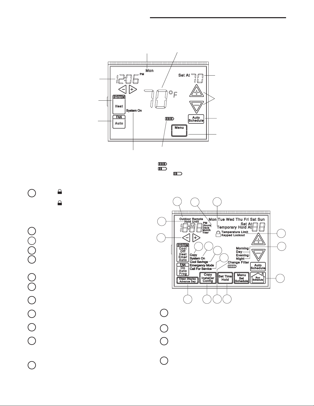
Time of Day
Day of Week
Room
Temperature
System
Switch
Fan
Switch
Indicates when
thermostat is calling
for Heat or Cool
Battery Level Indicator
Indicating the current power level
of the 2 “AA” batteries.
Full power remaining.
Half power remaining.
Change The batteries should be replaced at this time.
Menu key for entering
different modes such as
Configuration, Set Time,
Set Schedule and Cleaning
Enters user-friendly
program into
the schedule
Temperature
UP/Down used for
modifying set point
as well as to
navigating the menus
Set Temperature
THERMOSTAT QUICK REFERENCE
13
14
15
16
16
15
14
13
12
11
10
9
8
76
54
3
2
1
Home Screen Description
Figure 2 – Home Screen Display
Programming and Conguration Items
Displays and "Keypad Lockout" when in keypad
lockout mode.
Displays
Lockout" when limited range is activated and locked.
Displays only "Temperature Limit" when limited range
is activated.
Indicates period of day being programmed.
RUN SCHEDULE (run program) button.
SET TIME button or HOLD temperature button.
Displays "Change Filter" when the system has run
for the programmed lter time period as a reminder to
change or clean your lter.
COPY button or INSTALLER CONFIG button.
CLEAN DISPLAY button allows 30 seconds to wipe off
the display or ADVANCE DAY button for programming.
Used in programming to set time and in conguration
menu to change selections.
"Hold Until" indicates the time when a temporary hold
period will end.
"Hours" and "Days" displays during steps in installer
conguration.
The words "Hold At" are displayed when the thermo-
stat is in the HOLD mode. "Temporary Hold At" is
displayed when the thermostat is in a temporary HOLD
mode.
"Call For Service" indicates a fault in the heating/cool-
ing system. It does not indicate a fault in the thermostat.
4
and "Temperature Limit" and "Keypad
Figure 3 – Programming & Conguration Items
"System On" indicates when heating or cooling stage
is energized.
"Copy" indicates the copy program feature is being
used during programming.
A steady "Cool Savings" display indicates the feature
is enabled in the installer menu. A ashing "Cool Savings" display indicates the feature is active.
"Remote" indicates that the indoor remote temperature
sensor, is being accessed. "Outdoor Remote" indicates the outdoor remote temperature sensor is being
accessed.
 Loading...