


Blue Single 1/1 Stage Thermostat with Automatic Heat/Cool Changeover Option
Save these instructions for future use!
FAILURE TO READ AND FOLLOW ALL INSTRUCTIONS CAREFULLY BEFORE INSTALLING OR OPERATING THIS CONTROL COULD CAUSE PERSONAL INJURY AND/OR PROPERTY DAMAGE.
Single Stage or Heat Pump Installation and Operating Instructions for Model:
Model |
Programming Choices |
||
|
|
|
|
1F80-0471 |
5/2 Day |
5/1/1 Day |
Non-Programmable |
1F86-0471 |
Non-Programmable |
||
APPLICATIONS
THERMOSTAT APPLICATION GUIDE |
|
1F80-0471 Thermostat |
|
|
|
||
Description |
|
|
|
Gas or Oil Heat |
|
Yes |
|
Electric Furnace |
|
Yes |
|
Heat Pump (No Aux. or Emergency Heat) |
|
Yes |
|
Heat Pump (with Aux. or Emergency Heat) |
|
No |
|
Systems with up to 3 Stages Heat, 2 Stages Cool |
|
No |
|
Heat Only Systems |
|
Yes |
|
Millivolt Heat Only Systems – Floor or Wall Furnaces |
|
Yes |
|
Cool Only Systems |
|
Yes |
|
Hydronic (Hot Water) Zone Heat – 2 Wires |
|
Yes |
|
Hydronic (Hot Water) Zone Heat – 3 Wires |
|
Yes |
|
SPECIFICATIONS
Electrical Rating: |
|
Battery Power. . . . . . . . . . . . . . . . . . . . . . . . . . |
mV to 30 VAC, NEC Class II, 50/60 Hz or DC |
Input-Hardwire . . . . . . . . . . . . . . . . . . . . . . . . . |
20 to 30 VAC |
Terminal Load . . . . . . . . . . . . . . . . . . . . . . . . . . . . . |
1.0 A per terminal, 1.5A maximum all terminals combined |
Setpoint Range . . . . . . . . . . . . . . . . . . . . . . . . . . . . |
45° to 90°F (7° to 32°C) |
Differential (Single Stage) . . . . . . . . . . . . . . . . . . . . |
Heat 0.6°F; Cool 1.2°F (adjustable) |
Differential (Heat Pump) . . . . . . . . . . . . . . . . . . . . . |
Heat 1.2°F; Cool 1.2°F (adjustable) |
Operating Ambient. . . . . . . . . . . . . . . . . . . . . . . . . . |
32° to +105°F (0° to +41°C) |
Operating Humidity . . . . . . . . . . . . . . . . . . . . . . . . . |
90% non-condensing max. |
Shipping Temperature Range . . . . . . . . . . . . . . . . . |
-4° to +150°F (-20° to +65°C) |
Dimensions Thermostat. . . . . . . . . . . . . . . . . . . . . . |
3.4"H x 4.4"W x 1.3"D |
|
|
! CAUTION
To prevent electrical shock and/or equipment damage, disconnect electric power to system at main fuse or circuit breaker box until installation is complete.
Index |
Page |
Installation |
2 |
Wiring Connections |
2 |
Thermostat Quick Reference |
3 |
Installer Configuration Menu |
4 |
Operating Your Thermostat |
6 |
Programming |
6 |
Troubleshooting |
8 |
ATTENTION: MERCURY NOTICE
This product does not contain mercury. However, this product may replace a product that contains mercury.
Mercury and products containing mercury must not be discarded in household trash. Do not touch any spilled mercury. Wearing non-absorbent gloves, clean up any spilled mercury and place in a sealed container. For proper disposal of a product containing mercury or a sealed container of spilled mercury, place it in a suitable shipping container. Refer to www.white-rodgers.com for location to send product containing mercury.
www.white-rodgers.com |
PART NO. 37-6749D |
Replaces 37-6749C |
|
|
0902 |
INSTALLATION
!WARNING
Thermostat installation and all components of the control system shall conform to Class II circuits per the NEC code.
Remove Old Thermostat
A standard heat/cool thermostat consists of three basic parts:
1.The cover, which may be either a snap-on or hinge type.
2.The base, which is removed by loosening all captive screws.
3.The switching subbase, which is removed by unscrewing the mounting screws that hold it on the wall or adapter plate. Before removing wires from old thermostat, label each wire with the terminal designation from which it was attached. Disconnect the wires from the old thermostat one at a time. Do not let wires fall back into the wall.
Installing New Thermostat
1.Pull the thermostat body off the thermostat base. Forcing or prying on the thermostat will cause damage to the unit.
2.Place base over hole in wall and mark mounting hole locations on wall using base as a template.
3.Move base out of the way. Drill mounting holes. If you are using existing mounting holes and the holes drilled are too large and do not allow you to tighten base snugly, use plastic screw anchors to secure the base.
4.Fasten base snugly to wall using mounting holes shown in Figure 2 and two mounting screws. Leveling is for appearance only and will not affect thermostat operation.
5.Connect wires to terminal block on base.
6.Push excess wire into wall and plug hole with a fire resistant material (such as fiberglass insulation) to prevent drafts from affecting thermostat operation.
7.Carefully line the thermostat up with the base and snap into place.
SS/HP Switch
(Conventional or Heat Pump Selection)
The SS/HP switch is factory set to the SS position. In this position, thermostat is configured as conventional single stage. If you have a single stage heat pump system, switch SS/HP to HP position (see figure 2).
Gas/Elec Switch (Fan Option)
The GAS/ELEC switch is factory set to the GAS position. In this position, the thermostat will not power the circulator fan on a call for heat, but will power the circulator on a call for cool.
If your system requires that the thermostat power the circulator fan on a call for heat, this switch should be set to the ELEC position. Typically, gas and oil heating systems do not require the thermostat to power the circulator fan during a call for heat. If your heat is gas or oil, the switch should be set to the GAS position.
When the thermostat is configured for Heat Pump, the thermostat will always power the circulator fan on a call for heat in the HEAT mode.
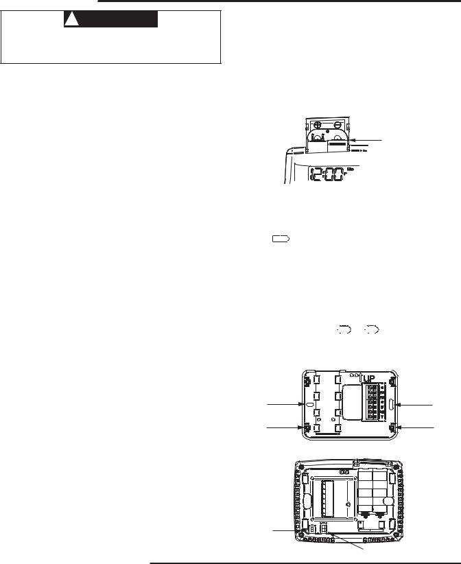
Batteries
2 "AA" alkaline batteries are included in the thermostat. To install the batteries, pull the battery door as shown by the arrow and lift open. Using the polarity indicated inside the battery door, insert the batteries. To close the battery door, swing the door down while pulling in the direction of arrow. Once fully down, snap the door back into position.
To replace the batteries, set system to OFF, following the instructions above.
Figure 1 – Battery door shown open
“AA” Alkaline Batteries |
Thermostat can be powered by system AC power or Battery. If is displayed, the thermostat is battery powered. If
  is not displayed, thermostat is system powered with optional battery back-up. When battery power remain-
ing is approximately half, the will be displayed. When "Change
 " is displayed, install fresh “AA” alkaline batteries immediately. For best results, replace all batteries with a premium brand alkaline battery such as Duracell® or Energizer®. We recommend replacing batteries every 2 years. If the home is going to be unoccupied for an extended period (over 3 months) and
 is displayed, the batteries should be replaced before leaving. When less than two months of battery life remain, the setpoint temperature will offset by
10 degrees (10 degrees cooler in Heat mode / 10 degrees warmer in Cool mode). If offset occurs, the normal setpoint can be manually reset with 


 or
or 

 . Another offset will
occur within two days if batteries are not replaced.
Figure 2 – Thermostat base and rear view of thermostat
Mounting |
Mounting |
Hole |
Hole |
Place Level |
Place Level |
across |
across |
Mounting Tabs |
Mounting Tabs |
(for appearance only) |
(for appearance only) |
SS/HP |
SS |
GAS |
Switch |
HP |
ELEC |
|
|
GAS/ELEC Switch
WIRING CONNECTIONS
Refer to equipment manufacturers' instructions for specific system wiring information. After wiring, see CONFIGURATION section for proper thermostat configuration. Refer to 37-6754 for 1F80-0471 wiring diagram specifications.
TERMINAL DESIGNATION DESCRIPTIONS
Terminal Designation |
Description |
Terminal Designation |
Description |
O/B ........................ |
(SS) Power closed for 3 wire zone |
RH ........................ |
Power for Heating |
|
HP) Changeover valve for heat pump |
RC ........................ |
Power for Cooling |
Y............................ |
Compressor Relay |
C.......................... |
Common wire from secondary side of |
W ........................... |
Heat Relay |
|
cooling system transformer or heat |
G............................ |
Fan Relay |
|
only system transformer |
2

THERMOSTAT QUICK REFERENCE
Home Screen Description
Displays the power level of the 2 "AA" batteries:

 indicates good power level.
 indicates batteries at about
half power. “Change 
 ” indicates batteries are low and should be replaced with 2 new premium brand “AA” Alkaline batteries.
SYSTEM
Indicator
Figure 4 – Home Screen Display
Time |
|
|
|
|
Room |
|
|
|
|
|
|||||
Day of Week |
Temperature |
Setting |
|||||||||||||
|
|
|
|
||||||||||||
|
|
|
|
|
|
Temperature |
|||||||||
|
|
|
|
|
|
|
|
|
|
||||||
|
|
|
|
|
|
|
|
|
|
|
|
|
|
|
|
|
|
|
|
|
|
|
|
|
|
|
|
|
|
|
|
|
|
|
|
|
|
|
|
|
|
|
|
|
|
|
|
|
|
|
|
|
|
|
|
|
|
|
|
|
|
|
|
|
|
|
|
|
|
|
|
|
|
|
|
|
|
|
|
|
|
|
|
|
|
|
|
|
|
|
|
|
|
|
|
|
|
|
|
|
|
|
|
|
|
|
|
|
|
|
|
Temperature Up/Down

 HOLD Button
SYSTEM |
FAN |
|
|
|
Button |
|
|
||
Indicator |
FAN |
MENU/SCHEDULE/RUN |
||
|
||||
|
|
Button |
Button |
Figure 5 – Programming & Configuration Items |
|
2 |
1 |
|
4 |
8 |
|
3 |
10 |
9 |
|
5 |
7 |
|
|
6
Programming and Configuration Items
1Flame icon 
 ) is displayed when the system is in HEAT mode. Snowflake icon (

 ) is displayed when the system is in COOL mode.
2The word "Hold" is displayed when the thermostat is in the HOLD mode. "Temp Hold" is displayed when the thermostat is in a Temporary HOLD mode.
3Displays "Change Filter" when the system has run for the programmed filter time period as a reminder to change or clean your filter.
4 Displays "Set" for setpoint when in Run Program mode.
5Displays System Mode (Heat, Cool, Auto, Off) or "Time" in menu mode.
6Displays Fan Mode (On, Auto) or "Run" in Menu mode or "Saving" in Cool SavingsTM Mode.
7Displays "Run Schedule", "Schedule", or "Menu".
8Displays "Save" when Cool SavingsTM is working.
9Displays "Heat Pump" when system is configured as Heat Pump thermostat.
10Displays "Hold" in programmable mode when in "Hold" mode. Displays Light Bulb in non-program- mable mode.
3

INSTALLER/CONFIGURATION MENU
With thermostat in Heat, Cool or Auto, in normal operation, press the Menu button for at least 5 seconds. The display will show item #1 in the table below. Press Menu to advance to the next menu item. Press 


 or
or 

 to change an item option. Shaded items are not available on 1F86.
INSTALLER/CONFIGURATION MENU
MENU |
|
|
PRESS |
DISPLAYED |
Press |
|
|
|
or |
|
|
|
|
to |
|
|
|
|
|
|
|
|
|
|
|
|
|||||||
REF |
HP |
SS |
BUTTON |
(FACTORY DEFAULT) |
select from listed |
|
options |
COMMENTS |
||||||||
|
||||||||||||||||
1 |
1 |
|
MENU |
On (Cool O) |
|
Heat b On |
|
Reversing Valve Output (SS/HP switch |
||||||||
|
|
|
must be in the Heat Pump HP position) |
|||||||||||||
|
|
|
|
|
|
|
|
|
|
|
|
|
|
|
||
2 |
2 |
1 |
MENU |
P (2) |
|
P 3, P 0 |
|
Selectable Programs Per Week |
||||||||
|
|
(For programmable thermostat only) |
||||||||||||||
|
|
|
|
|
|
|
|
|
|
|
|
|
|
|
||
3 |
3 |
2 |
MENU |
Cool Saving CS (OFF) |
Cool Saving CS On |
Select Cool Savings on or off |
||||||||||
MENU |
CS (3) |
6, 5, 4, 2, 1 |
|
|
|
Selects Cool Savings value 1 (low) to 6 (high) |
||||||||||
|
|
|
|
|
|
|||||||||||
4 |
4 |
3 |
MENU |
E (On) |
|
|
E OFF |
|
Selects Energy Management Recovery (EMR) |
|||||||
|
|
|
on or off |
|||||||||||||
|
|
|
|
|
|
|
|
|
|
|
|
|
|
|
||
5 |
|
4 |
MENU |
CR Heat |
|
FA, SL |
|
Adjustable Anticipation (Heat) (only when |
||||||||
|
(ME) |
|
|
SS/HP switch is at the SS position) |
||||||||||||
|
|
|
|
|
|
|
|
|
|
|
|
|
|
|||
6 |
|
5 |
MENU |
CR Cool |
|
|
|
SL |
|
Adjustable Anticipation (Cool) (only when |
||||||
|
(FA) |
|
|
|
|
SS/HP switch is at the SS position) |
||||||||||
|
|
|
|
|
|
|
|
|
|
|
|
|
|
|||
7 |
5 |
|
MENU |
CR Heat Pump |
|
|
|
SL |
|
Adjustable Anticipation (Heat Pump) |
||||||
|
(FA) |
|
|
|
|
(only when SS/HP switch is at the HP position) |
||||||||||
|
|
|
|
|
|
|
|
|
|
|
|
|
|
|||
8 |
6 |
6 |
MENU |
CL (OFF) |
|
|
CL On |
|
Compressor Lockout Time |
|||||||
|
|
|
|
|
Heat Cool Off, |
|
|
|||||||||
|
|
|
|
Auto Heat |
Heat Off with Fan icon, |
System Mode Configuration |
||||||||||
9 |
7 |
7 |
MENU |
Heat Off without Fan |
||||||||||||
Cool Off |
with Automatic Changeover |
|||||||||||||||
|
|
|
|
icon, Cool Off, |
|
|||||||||||
|
|
|
|
|
|
|
||||||||||
|
|
|
|
|
|
Auto Off |
|
|
||||||||
|
|
|
|
|
|
|
|
|
|
|
|
|
|
|
|
|
10 |
8 |
8 |
MENU |
L (On) |
|
|
L OFF |
|
Selects Display Light on or off |
|||||||
11 |
9 |
9 |
MENU |
0 HI |
1 HI, 2 HI, 3HI, 4 HI, |
Adjustable Ambient Temperature Display |
||||||||||
1 LO, 2 LO, 3 LO, 4 LO |
||||||||||||||||
|
|
|
|
|
|
|||||||||||
12 |
10 |
10 |
MENU |
F |
|
|
|
|
C |
|
Selects Fahrenheit/Celsius Temperature Display |
|||||
|
|
|
MENU |
Change Filter (OFF) |
Change Filter On |
|
Selects Filter Change-out Indicator |
|||||||||
13 |
11 |
11 |
MENU |
Change Filter 200 h |
25 h to 1975 h in |
|
When on, selects time in 25 hour increments |
|||||||||
|
|
|
25-hour increment |
25-hour increment |
||||||||||||
|
|
|
|
|
||||||||||||
14 |
12 |
12 |
RUN |
|
|
|
|
|
|
|
|
|
|
|
Returns to Normal Operation |
|
1)Select Reversing Valve Output (SS/HP switch must be set at HP, omitted if SS/HP switch is SS Position) – The O/B option is factory set at "O" position. This will accommodate the majority of heat pump applications, which require the changeover relay to be energized in COOL. If the thermostat you are replacing or the heat pump being installed with this thermostat requires a "B" terminal, to energize the changeover relay in HEAT, the O/B option should be set at "B" position.
2)ProgramOptions1F80 only –This control can be configured for 5/2 day or 5/1/1 day programming or non-programming mode. The default setting is P2, indicating 5/2 day program-
ming. The programs per week can be toggled to P3 or P0 by pressing the 


 or
or 

 keys. A selection of 0 Days for non-programmable will eliminate the need for EMR, and that step in the menu will be skipped.
3)Select Cool Savings™ and value – Selects the Cool Savings feature On or OFF. If selected On, press MENU to select the amount of adjustment for the feature in Cool mode with 1 (1°) being the least amount of adjustment and 6 (6°) being the most amount of adjustment. Default value is 3 (3°). In normal operation "Saving" will appear under
"Fan".
Cool Savings is an optional energy saving feature that can reduce your cooling costs. It is based on the principal that lower indoor humidity makes a slightly higher temperature feel more comfortable. Cool Savings operates during periods of high demand which normally occur on the hottest summer days when the cooling system may run for hours to reach the thermostat setting. Long cooling run times also lower the indoor humidity. Cool Savings very slowly adjusts the setpoint temperature to make the setpoint closer to the displayed temperature, to a maximum number of degrees selected. Adjusting the setpoint temperature over a long cooling run time allows the system to reach your set temperature and turn off. The room temperature will actually be higher than the thermostat displays, but the reduction in humidity will allow comfort at the slightly higher temperature. When Cool Savings is making adjustments, "Save" will show next to the setpoint temperature and the room temperature may vary within the adjustment range selected.
If this feature is selected OFF, no change will occur when the cooling system is continually running during periods of high demand.
4

INSTALLER/CONFIGURATION MENU
4)Energy Management Recovery: (this step is skipped if configured to be non-programmable).
Energy Management Recovery (E) On enables the thermostat to start heating or cooling early to make the building temperature reach the program setpoint at the time you specify. Heating will start 5 minutes early for every 1° of temperature required to reach setpoint.
Example: If E On is selected and have your heating programmed to 65° at night and 70° at 7 AM. If the building temperature is 65°, the difference between 65° and 70° is 5°. Allowing 5 minutes per degree, the thermostat setpoint will change to 70° at 6:35 AM. Cooling allows more time per degree, because it takes longer to reach set temperature.
5, 6 & 7) Cycle Rate Selection – The factory default settings with SS/HP switch in SS position for Heat is medium cycle (ME) and Cool is fast cycle (FA). For Heat Pump (HP), the default setting is fast cycle (FA).
To change cycle rate, press the 

 or
or 


 key. Cycle rate differentials for different settings are:
MODE |
Fast |
Medium |
Slow |
||
FA |
ME |
SL |
|||
|
|
||||
Heat |
(SS) |
0.4°F |
0.6°F |
1.8°F |
|
Cool |
(SS) |
1.2°F |
– |
1.7°F |
|
Heat Pump (HP) |
1.2°F |
– |
1.7°F |
||
8)Select Compressor Lockout CL OFF or ON – Selecting CL ON will cause the thermostat to wait 5 minutes between cooling cycles. This is intended to help protect the compressor from short cycling. Some newer compressors already have a time delay built in and do not require this feature. Your compressor manufacturer can tell you if the lockout feature is already present in their system. When the thermostat compressor time delay occurs, it will flash the setpoint for up to five minutes.
9)System Mode Configuration – This thermostat is configured for Heat and Cool with Auto changeover (SYSTEM switch with Cool Off Heat Auto) default. It can also be configured for Heat and Cool (Cool Off Heat), Heat only with fan (Off Heat), Heat only without fan, Auto only (Auto Off), and Cool only (Cool Off).
10)Select Backlight Display – The display backlight improves display contrast in low lighting conditions. When the "C" terminal is powered, selecting backlight CdL ON will keep the light on continuously. Select backlight OFF will keep the light on momentarily after any key is pressed. When the "C" terminal is not powered, the light will be on momentarily after any key is pressed no matter whether the backlight is selected ON or OFF.
11)Select Temperature Display Adjustment 4 LO to 4 HI.
Allows you to adjust the room temperature display up to 4° higher or lower. Your thermostat was accurately calibrated at the factory, but you have the option to change the display temperature to match your previous thermostat. The current or adjusted room temperature will be displayed on the left side of the display.
12)Select F° or C° Readout – Changes the display readout to Centigrade or Fahrenheit as required.
13)Select Filter Replacement Reminder and Set Run Time.
Select the "Change Filter" reminder On or OFF. If selected On, press MENU to select the time period from 25 to 1975 hours in 25 hours increments. In a typical system, 200 hours (default) of run time is approximately 30 days. After the selected time of blower operation, the thermostat will display "Change Filter" as a reminder to change or clean your air filter. When "Change Filter" is displayed, press MENU button to clear the display and restart the time to the next filter change.
5
 Loading...