


 Loading...
Quick Installation Guide
00825-0100-4530, Rev EC
March 2013
Superior Performance
Guided Wave Radar
Level and Interface Transmitter

Quick Installation Guide |
March 2013 |
|
|
About this guide
This installation guide provides basic guidelines for Rosemount 5300 Series transmitters. It does not provide instructions for configuration, diagnostics, maintenance, service, troubleshooting, Explosion-proof, Flameproof, or intrinsically safe (I.S.) installations. Refer to the Rosemount 5300 Series Reference Manual (Document No. 00809-0100-4530) for more instruction. The manual and this Quick Installation Guide (QIG) are also available electronically on www.rosemount.com.
Failure to follow safe installation and service guidelines could result in death or serious injury
Make sure the transmitter is installed by qualified personnel and in accordance with applicable code of practice.
Use the equipment only as specified in this QIG and the Reference Manual. Failure to do so may impair the protection provided by the equipment.
Do not perform any services other than those contained in this manual unless you are qualified.
Explosions could result in death or serious injury
Verify that the operating environment of the transmitter is consistent with the appropriate hazardous locations specifications. See Product Certifications on page 25 in this Quick Installation Guide.
To prevent ignition of flammable or combustible atmospheres, disconnect power before servicing.
Before connecting a HART®, FOUNDATION™ fieldbus, or Modbus based communicator in an explosive atmosphere, make sure the instruments in the loop are installed in accordance with intrinsically safe or non-incendive field wiring practices.
To avoid process leaks, only use O-rings designed to seal with the corresponding flange adapter.
Electrical shock can result in death or serious injury
Avoid contact with the leads and terminals. High voltage that may be present on leads can cause electrical shock.
Make sure the main power to the Rosemount 5300 Series transmitter is off and the lines to any other external power source are disconnected or not powered while wiring the transmitter.
Probes with non-conducting surfaces
Probes covered with plastic and/or with plastic discs may generate an ignition-capable level of electrostatic charge under certain extreme conditions. Therefore, when the probe is used in a potentially explosive atmosphere, appropriate measures must be taken to prevent electrostatic discharge.
2
March 2013 |
Quick Installation Guide |
||
|
|
|
|
|
|
|
|
|
|
|
|
Any substitution of non-authorized parts or repair, other than exchanging the complete transmitter head or probe assembly, may jeopardize safety and is prohibited.
Unauthorized changes to the product are strictly prohibited as they may unintentionally and unpredictably alter performance and jeopardize safety. Unauthorized changes that interfere with the integrity of the welds or flanges, such as making additional perforations, compromise product integrity and safety. Equipment ratings and certifications are no longer valid on any products that have been damaged or modified without the prior written permission of Emerson Process Management. Any continued use of product that has been damaged or modified without prior written authorization is at the customer's sole risk and expense.
Eliminate the risk of ESD discharge prior to dismounting the transmitter head from the probe.
Probes may generate an ignitioncapable level of electrostatic charge under extreme conditions.
During any type of installation or maintenance in a potentially explosive atmosphere the responsible person should make sure that any ESD risks are eliminated before attempting to separate the probe from the transmitter head.
Contents
Confirm system readiness . . . . . . . . . . . . . . . . . 4 Safety Instrumented Systems (4-20 mA only) 21 Mount the transmitter head/probe . . . . . . . . . 5 Product certifications . . . . . . . . . . . . . . . . . . . . 25 Connect the wiring . . . . . . . . . . . . . . . . . . . . . . . 8
Configure . . . . . . . . . . . . . . . . . . . . . . . . . . . . . . 15
3

Quick Installation Guide |
March 2013 |
|
|
Step 1: Confirm system readiness
Confirm HART revision capability
If using HART-based control or asset management systems, confirm the HART capability of those systems prior to transmitter installation. Not all systems are capable of communicating with the HART Revision 7 protocol.
This transmitter can be configured for either HART Revision 5 or 7.
For instructions on how to change the HART revision of your transmitter, see
“Switch HART revision mode” on page 4.
Confirm correct Device Driver
Verify that the latest Device Driver (DD/DTM) is loaded on your systems to ensure proper communication.
Download the latest Device Driver from www.rosemount.com/LevelSoftware.
Rosemount 5300 device revisions and drivers
Table 1 provides the information necessary to ensure that you have the correct Device Driver and documentation for your device.
Table 1. Rosemount 5300 device revisions and files
Firmware |
Find Device Driver |
Review Instructions |
Review Functionality |
||
1 |
HART |
Device |
|
|
3 |
Version |
Universal |
Manual Document Number |
Changes to Software |
||
|
Revision2 |
|
|||
|
Revision |
|
|
|
|
2F0 and later |
7 |
4 |
00809-0100-4530 |
See footnote 3 for list of |
|
|
|
||||
5 |
3 |
Rev EA |
changes. |
|
|
|
|
||||
|
|
|
|
||
|
|
|
|
|
|
2A2 - 2D2 |
5 |
3 |
00809-0100-4530 |
N/A |
|
Rev DA |
|
||||
|
|
|
|
|
|
1.Firmware version is printed on the transmitter head label, e.g. SW 2E0.
2.Device revision is printed on the transmitter head label, e.g. HART Dev Rev 4.
3.HART Revision 5 and 7 are selectable.
Switch HART revision mode
If the HART configuration tool is not capable of communicating with HART Revision 7, the Rosemount 5300 Series will load a Generic Menu with limited capability. The following procedures will switch the HART revision mode from the Generic Menu:
1.Manual Setup > Device Information > Identification > Message
To change to HART Revision 5, Enter: “HART5” in the Message field
To change to HART Revision 7, Enter: “HART7” in the Message field
4
March 2013 |
Quick Installation Guide |
Step 2: Mount the transmitter head/probe
 Transmitter
Housing
Nut
Bolt 


 Flange
Probe
Gasket
Tank
Flange
Nut |
|
Adapter |
Sealant on |
Probe |
|
|
|
|
|
threads (NPT) |
|
|
|
|
|
or |
|
|
|
|
|
|
|
|
|
|
|
|
|
|
Gasket (BSP/G) |
|
|
|
|
|
|
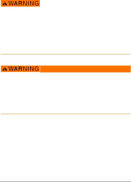
Tank connection with flange
1.Place a gasket on top of the tank flange.
2.Lower the probe with flange into the tank.
3.Tighten the bolts and nuts with sufficient torque regarding flange and gasket choice.
4.Loosen the nut that connects the housing to the probe and rotate the housing to the desired direction.
5.Tighten the nut.
Threaded tank connection
1.For adapters with BSP/G threads, place a gasket on top of the tank flange.
2.Lower the probe into the tank.
3.Mount the adapter into the process connection.
4.Loosen the nut that connects the housing to the probe and rotate the housing to the desired direction.
Tank Flange/
Process
Connection
Nut
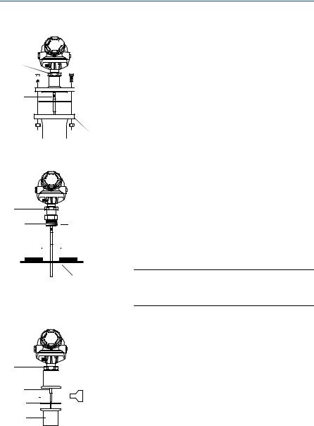
 Tri-Clamp
Probe


 Clamp
Clamp
Gasket
Tank
5. Tighten the nut.
NOTE:
For adapters with NPT threads, pressure-tight joints require a sealant.
Tri-Clamp tank connection
1.Place a gasket on top of the tank flange.
2.Lower the transmitter and probe into the tank.
3.Fasten the Tri-Clamp to the tank with a clamp.
4.Loosen the nut that connects the transmitter housing to the probe slightly.
5.Rotate the transmitter housing so the cable entries/display face the desired direction.
6.Tighten the nut.
Refer to the Rosemount 5300 Series Reference Manual (Document No. 00809-0100-4530) for details regarding the mounting of transmitter head/probe.
5
Quick Installation Guide |
March 2013 |
|
|
Step 2 continued...
Transmitter
 housing
Bracket
Probe
U-bolts |
Clamping |
|
brackets |
|
Bracket |
Transmitter |
|
housing |
|
Probe
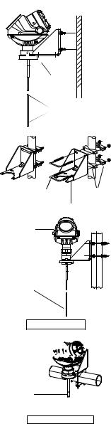
Vertical mounting
Transmitter 


 housing


Probe
Horizontal mounting
Bracket mounting, on wall
1.Mount the bracket directly to the wall with screws suitable for the purpose.
2.Mount the transmitter with probe to the bracket and secure the installation with the three supplied screws.
Bracket mounting, on pipe
1.Put the two U-bolts through the holes of the bracket. Holes are available for both vertical and horizontal pipe mounting.
2.Put the clamping brackets on the U-bolts and around the pipe.
3.Fasten the bracket to the pipe using the four supplied nuts.
4.Mount the transmitter with probe to the bracket and secure with the three supplied screws.
See the Rosemount 5300 Series Reference Manual (Document No. 00809-0100-4530) for more installation details.
6
March 2013 |
Quick Installation Guide |
|
|
Step 2 continued...


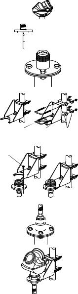
 M50 nut
U-bolt Bracket Clamping
brackets
M6 screw
M50 nut

Remote housing
1.Remove the transmitter head from the probe by unscrewing the M50 nut.
For safety information regarding ESD discharge, see the applicable warning on page 3.
2.Mount the probe in the tank.
3.Mount the bracket to the pole, making sure the distance between the probe and bracket does not exceed the length of the remote connection.
Put the two U-bolts through the holes of the bracket. Several holes are available for vertical/horizontal pipe mounting.
Put the clamping brackets on the U-bolts and around the pipe.
Use the supplied nuts to fasten the bracket to the pipe.
4.Fasten the housing support to the bracket using the M6 screws. The screws are threaded through the top of the mounting bracket and into the housing support.
5.Mount the probe housing on the probe, making sure that the M50 nut is properly tightened.
6.Connect the transmitter head on the housing support, making sure that the M50 nut is properly tightened.
7

Quick Installation Guide |
March 2013 |
|
|
Step 3: Connect the wiring
Wiring and power supply requirements can be dependent upon the approval certification. As with all FOUNDATION fieldbus requirements, a conditioned power supply and terminating resistors are required for proper operation.
It is recommended that shielded twisted pair wiring (18-12 AWG) suitable for the supply voltage be used and, if applicable, approved for use in hazardous areas. For electrical information, such as power supply, see diagrams and drawings for HART, Modbus, and FOUNDATION fieldbus on the following pages.
NOTE:
Avoid running instrument cable next to power cables in cable trays or near heavy electrical equipment.
It is important that the instrument cable shield be:
-trimmed close and insulated from touching the transmitter housing
-continuously connected throughout the segment
-connected to a good earth ground at the power supply end
Grounding
When wiring the transmitters, the grounding should be completed such that:
The loop is grounded at the power supply.
When transmitters are installed on metal tanks, ensure there is a metal-to-metal connection between the device and the tank.
If the tank is non-metallic, the housing must be grounded to an earth ground that is separate from the power supply. The external ground terminal may be used for this purpose.
If the tank is cathodically protected, the housing must be grounded to an earth ground that is outside of the cathodic protection system ground. Use the external terminal for this purpose.
When transient protection terminal block is used, the ground wire should be separate from the signal wire. Use the external ground terminal.
Make sure grounding is done (including IS ground inside Terminal compartment) according to Hazardous Locations Certifications, national and local electrical codes.
The most effective transmitter housing grounding method is a direct connection to earth ground with minimal (< 1 ) impedance.
NOTE:
Grounding the transmitter housing using the threaded conduit connection may not provide a sufficient ground. The transient protection terminal block will not provide transient protection unless the transmitter housing is properly grounded. Use the above guidelines to ground the transmitter housing. Do not run transient protection ground wire with signal wiring; the ground wire may carry excessive current if a lightning strike occurs.
8
March 2013 |
Quick Installation Guide |
To connect the transmitter
1.Verify that the power supply is disconnected.
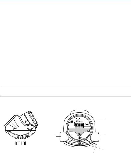
2.Remove the terminal block cover (see picture below).
3.Pull the cable through the cable gland/conduit. For Explosion-proof / Flameproof installations, only use cable glands or conduit entry devices certified Explosion-proof or Flameproof. Install wiring with a drip loop where the bottom of the loop must be lower than the cable/conduit entry.
4.To connect the wires, see the illustrations on the following pages.
5.Use the enclosed metal plug to seal any unused port.
6.Tighten the cable gland.
7.Mount the cover and make sure it is fully engaged to meet Explosion-proof requirements (adapters are required if M20 glands are used).
For ATEX, IECEx, NEPSI, INMETRO, and TIIS installations, lock the cover with the locking screw.
8.Connect the power supply.
NOTE:
Use PTFE tape or other sealant at the NPT threads in the Cable Entries.
Terminal block
Terminal
Block
Cover
Cable Entry, ½ in. NPT - 14 or M20x1.5 adapter
External Ground Screw
Remove the orange, protective, plastic plugs, used for transportation.
Seal any unused port with the enclosed metal plug.
Terminals for signal and power supply
Cable Entry, ½ in. NPT - 14 or M20x1.5 adapter
Internal Ground
Screw
Locking screw
9

Quick Installation Guide |
March 2013 |
|
|
Step 3 continued...
HART communication
The Rosemount 5300 Series transmitter operates with a power supply ranging from 16 - 42.4 Vdc (16 - 30 Vdc in IS applications, 20-42.4 Vdc in Explosion-proof / Flameproof applications and in Non-Sparking / Energy Limited applications).
All configuration tools for HART communication, such as the Field Communicator and Rosemount Radar Master, require a minimum load resistance (RL) of 250 within the loop in order to function properly, see diagrams below.
Non-intrinsically safe power supply
|
|
|
Field |
Rosemount 5300 Series |
|
|
PC |
Communicator |
Transmitter |
|
|
|
|
|
|
|
HART |
|
|
|
|
Modem |
|
|
Power |
Load Resistance |
|
|
|
Supply |
|
|
||
250 |
|
|
|
|
|
|
|
||
NOTE:
Rosemount 5300 Series Transmitters with Flameproof/Explosion-proof output have a built-in barrier; no external barrier needed.
Intrinsically safe power supply
|
|
|
Field |
Rosemount 5300 Series |
|
PC |
Communicator |
Transmitter |
|
|
HART |
|
||
|
|
|
Modem |
|
Power |
|
|
|
|
Supply |
RL 250 |
|
|
|
|
|
|
||
ApprovedIS
Barrier
For IS Parameters, see the Product certifications chapter.
10
March 2013 |
Quick Installation Guide |
|
|
Step 3 continued...
Type n approvals : non-sparking / energy limited power supply
|
|
|
|
Field |
Rosemount 5300 Series |
|
|
PC |
|
Communicator |
Transmitter |
|
|
HART |
|
|
|
|
|
|
|
|
|
|
|
|
Modem |
|
|
Power |
Load Resistance |
|
|
||
Supply |
|
|
|||
250 |
|
|
|
|
|
|
|
|
|
||
HART: Un = 42.4 V
Transient protection terminal block
|
|
|
|
Field |
Rosemount 5300 Series |
|
|
PC |
HART |
Communicator |
Transmitter |
|
|
Transient |
|
||
|
|
|
|
||
|
|
|
Modem |
|
|
|
|
|
Protection |
|
|
|
|
|
|
|
|
|
|
|
|
Symbol |
|
Power |
Load Resistance |
|
|
||
Supply |
|
|
|||
250 |
|
|
|
|
|
HART: Un = 42.4 V
11
Loading...