


OVLERQ*D OVLSRQ*D OVLESRQ*G OVLSERQ*G
 Owners Manual
OVL™ Series Water Coolers Refrigerated Fountains with Back Panel
Fig. 1 – OVL-II ER |
Fig. 2 – OVL-II SR |
Fig. 3 – OVL-II SER |
Fig. 4 – OVL-II ESR |
||||
|
|
|
|
|
|
|
|
|
Figure |
|
Model |
|
Description |
|
|
|
|
|
|
|
|
|
|
|
1 |
|
OVL-II ER |
|
OVL-II Series - Extended Reach |
|
|
|
2 |
|
OVL-II SR |
|
OVL-II Series - Standard Reach |
|
|
|
3 |
|
OVL-II SER |
|
OVL-II Series - Dual Installation |
|
|
|
4 |
|
OVL-II ESR |
|
OVL-II Series - Dual Installation |
|
|
INSTALLER
Review these instructions before beginning installation. Be sure that installation conforms to all plumbing, electrical and other applicable codes.
When installation is complete, ensure these instructions are left in the plastic bag provided inside the installed unit for future reference.
Service to be performed by authorized service personnel only.
NOTE: It is common practice to ground electrical hardware such as telephones, computers and other devices to available water lines. This can, however, cause electrical feedback in the plumbing circuit, which results in an “electrolysis” effect occurring in the fountain. This may result in water which has a metallic taste to it or has a noticeable increase in the metallic content of the water.
When inspecting plumbing circuit, remember the line may be grounded some distance from the installation, and may occur outside the building or area in which the unit is being installed.
This condition can be avoided (in most cases) by using recommended materials during installation. Any drain fittings provided by the installer should be made of plastic which will electronically isolate the fountain from the remainder of the building’s plumbing circuits.
Page 1 |
97881C - (Rev. L- 07/16) |
OVLERQ*D OVLSRQ*D OVLESRQ*G OVLSERQ*G
1/4” O.D. TUBE |
3/8” O.D. UNPLATED COP- |
BUILDING WATER |
WATER INLET |
PER TUBE CONNECT |
|
TO COOLER |
COLD WATER SUPPLY |
INLET |
NOTE: WATER FLOW |
SERVICE STOP |
DIRECTION |
(NOT FURNISHED) |
Figure 5 – Water Supply Connections
Parts List
Installation Package
The components for installation are packed in three separate boxes, regardless of the type of unit being installed. The boxes contain the following:
Box No. 1: Wall Frame(s)
Box No. 2: Remote Chiller, SJ8
Box No. 3: Fountain(s), Arm(s) and Panels
Additional materials, as noted in the Parts List, are also shipped in these boxes.
Number Required
|
|
|
OVL-II ER |
OVL-II SR |
OVL-II SER |
OVL-II ESR |
See |
|
Item |
Part No. |
Description |
Fig. |
|
||||
1 |
26990C |
Bottom Cover - Standard Reach |
- |
1 |
1 |
1 |
27 |
|
|
|
|
|
|
|
|
|
|
|
26988C |
Bottom Cover - Extended Reach |
1 |
- |
1 |
1 |
27 |
|
2 |
55836C |
Push Arm Actuator Plate |
1 |
1 |
2 |
2 |
23 |
|
|
55991C |
Push Arm Actuator Plate - A.G. |
1 |
1 |
2 |
2 |
23 |
|
3 |
51546C |
Bubbler |
1 |
1 |
2 |
2 |
27 |
|
|
45396C |
Bubbler - A.G. |
1 |
1 |
2 |
2 |
27 |
|
|
|
Bubbler - EasyFlex (option) |
1 |
1 |
2 |
2 |
- |
|
|
98481C |
Kit - VR Bubbler-Smart Flow™ |
1 |
1 |
2 |
2 |
26 |
|
4 |
1000001791 |
Kit - VR Bubbler Nipple/Gaskets |
1 |
1 |
2 |
2 |
26 |
|
|
1000002705 |
Kit - Bubbler Nipple/Gaskets |
1 |
1 |
2 |
2 |
26 |
|
5 |
160270508640 |
Strainer Plate - S.S. |
1 |
1 |
2 |
2 |
27 |
|
|
45400C |
Strainer Plate - A.G. |
1 |
1 |
2 |
2 |
23 |
|
6 |
101570540560 |
Drain Gasket |
1 |
1 |
2 |
2 |
27 |
|
7 |
51575C |
Packing Ring |
1 |
1 |
2 |
2 |
27 |
|
8 |
110346220550 |
Drain Nut |
2 |
2 |
4 |
4 |
27 |
|
9 |
101637451550 |
Friction Ring |
1 |
1 |
2 |
2 |
27 |
|
|
|
|
|
|
|
|
|
|
10 |
161637308640 |
Drain Plug - S.S. |
1 |
1 |
2 |
2 |
27 |
|
|
|
|
|
|
|
|
|
|
|
45398C |
Drain Plug - A.G. |
1 |
1 |
2 |
2 |
27 |
|
|
|
|
|
|
|
|
|
|
11 |
45683C |
Drain Tube |
1 |
- |
1 |
1 |
27 |
|
|
|
|
|
|
|
|
|
|
|
45682C |
Drain Tube |
- |
1 |
1 |
1 |
27 |
|
12 |
100023340560 |
Waste Tube Gasket |
1 |
1 |
2 |
2 |
27 |
|
13 |
161570808550 |
Slip Nut |
1 |
1 |
2 |
2 |
27 |
|
|
|
|
|
|
|
|
|
|
14 |
61314C |
Regulator |
1 |
1 |
2 |
2 |
25 |
|
|
|
|
|
|
|
|
|
|
15 |
1000002145 |
Kit - Regulator Holder (5 Pack) |
1 |
1 |
2 |
2 |
25 |
|
|
|
|
|
|
|
|
|
|
16 |
27006C |
Basin - S.S. |
1 |
1 |
2 |
2 |
23,26,26 |
|
|
|
|
|
|
|
|
|
|
|
27342C |
Basin - A.G. |
1 |
1 |
2 |
2 |
27 |
|
|
|
|
|
|
|
|
|
|
|
|
Basin - Galaxy Gray Marblyte (option) |
1 |
1 |
2 |
2 |
- |
|
|
|
Basin - Golden Sand Marblyte (option) |
1 |
1 |
2 |
2 |
- |
|
|
|
Basin - Black Onyx Marblyte (option) |
1 |
1 |
2 |
2 |
- |
|
17 |
27000C |
Basin Liner - S.S. |
1 |
1 |
2 |
2 |
27 |
|
|
27344C |
Basin Liner - A.G. |
1 |
1 |
2 |
2 |
27 |
|
18 |
70861C |
Screw - #10-24 X 2.00 |
4 |
4 |
8 |
8 |
27 |
|
19 |
55840C |
Top Plate - Actuator |
1 |
1 |
2 |
2 |
23 |
|
20 |
55839C |
Bottom Plate - Actuator |
1 |
1 |
2 |
2 |
23 |
|
21 |
27338U |
Extended Reach Arm - S.S. |
1 |
- |
1 |
1 |
27 |
|
|
27338C |
Extended Reach Arm - A.G. |
1 |
- |
1 |
1 |
27 |
|
|
27340U |
Standard Reach Arm - S.S. |
- |
1 |
1 |
1 |
27 |
|
|
27340C |
Standard Reach Arm - A.G. |
- |
1 |
1 |
1 |
27 |
|
22 |
28328C |
Regulator Mounting Bracket |
1 |
1 |
2 |
2 |
24 |
|
97881C - (Rev. L - 07/16) |
Page 2 |
OVLERQ*D OVLSRQ*D OVLESRQ*G OVLSERQ*G
Parts List Continued
Item |
Part No. |
Description |
OVL-II ER |
OVL-II SR |
OVL-II SER |
OVL-II ESR |
|
See |
|
||||||||
|
Fig. |
|||||||
23 |
1000002027 |
Kit - Nut-Retaining (5 Pack) |
1 |
1 |
2 |
2 |
|
|
24 |
1000001926 |
Kit - Hex Nut-Unplated (4 Pack) |
1 |
1 |
2 |
2 |
|
|
25 |
27008C |
Reaction Bracket |
1 |
1 |
2 |
2 |
|
|
26 |
70856C |
Screw - #10-24 x .38 PHMS |
1 |
1 |
2 |
2 |
|
|
27 |
70854C |
Rod - Pivot |
1 |
1 |
2 |
2 |
|
|
28 |
50198C |
Bushing Snap |
4 |
4 |
8 |
8 |
|
|
29 |
0000001323 |
Kit - Pivot Bracket/Bushing/Bumper/Rod |
1 |
1 |
2 |
2 |
|
|
30 |
28327C |
Arm - Regulator Activating |
1 |
1 |
2 |
2 |
|
|
31 |
28326C |
Arm - Regulator Adjustment |
1 |
1 |
2 |
2 |
|
|
32 |
22797C |
Upper Panel (OVL-II ER) - S.S. |
1 |
- |
- |
- |
|
|
|
27886C |
Upper Panel (OVL-II ER) - A.G. |
1 |
- |
- |
- |
|
|
|
22799C |
Upper Panel (OVL-II SR) - S.S. |
- |
1 |
- |
- |
|
|
|
27888C |
Upper Panel (OVL-II SR) - A.G. |
- |
1 |
- |
- |
|
|
|
26958C |
Upper Panel (OVL-II SER) - S.S. |
- |
- |
1 |
- |
|
|
|
27890C |
Upper Panel (OVL-II SER) - A.G. |
- |
- |
1 |
- |
|
|
|
22795C |
Upper Panel (OVL-II ESR) - S.S. |
- |
- |
- |
1 |
|
|
|
27892C |
Upper Panel (OVL-II ESR) - A.G. |
- |
- |
- |
1 |
|
|
|
1000003515 |
Upper Panel (OVL-II ER-GRN) S.S. |
1 |
- |
- |
- |
|
|
|
1000003517 |
Upper Panel (OVL-II SER-GRN) S.S. |
- |
- |
1 |
- |
|
|
|
1000003518 |
Upper Panel (OVL-II ESR-GRN) S.S. |
- |
- |
- |
1 |
|
|
33 |
26833C |
Lower Panel (OVL-II ER/SR) - S.S. |
1 |
1 |
- |
- |
|
|
|
27894C |
Lower Panel (OVL-II ER/SR) - A.G. |
1 |
1 |
- |
- |
|
|
|
27026C |
Lower Panel (OVL-II SER/ESR) - S.S. |
- |
- |
1 |
1 |
|
|
|
27896C |
Lower Panel (OVL-II SER/ESR) - A.G. |
- |
- |
1 |
1 |
|
|
34 |
55996C |
Strainer (Supplied with Chiller) |
1 |
1 |
1 |
1 |
|
|
35 |
1000002162 |
Kit - Union-1/4” (3 Pack) |
1 |
1 |
1 If Filtered |
1 If Filtered |
|
|
36 |
1000001994 |
Kit - Tee-1/4” (3 Pack) |
- |
- |
1 |
1 |
|
|
37 |
56092C |
Poly Tubing - 1/4” (Cut To Length) |
1 |
1 |
1 |
1 |
|
|
NS = Not Shown
NOTE: S.S. means Stainless Steel
A.G. means Aztec Gold
N-S means not shown
Page 3 |
97881C - (Rev. L- 07/16) |
OVLERQ*D OVLSRQ*D OVLESRQ*G OVLSERQ*G
Note: Danger! Electric shock hazard. Disconnect power before servicing unit.
Uses HFC-134A refrigerant
Models
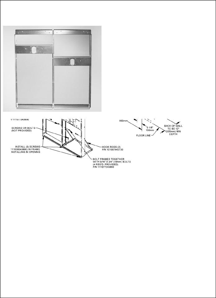
OVL-II SER – OVL-II ESR
1. Cut a rectangular wall opening 37-1/2” (953 mm) W
|
|
x 37-3/4” H (959 mm) and 4-1/2” (114 mm) above the |
|
|
floor line (see Figure 7). The dimensions are required |
|
|
to obtain proper rim and bubbler heights for compliance |
|
|
with ANSI standard A117.1. |
|
2. Reinforce the wall opening on all sides to adequately |
|
|
|
support the water fountain. This reinforcement must |
|
|
support up to 150 lbs. W load and provide a means for |
|
|
securing the frame assembly in place. |
|
|
NOTE: Building construction must allow for adequate |
|
|
air flow on both sides and top of remote chiller |
|
|
unit a minimum of 4” (102 mm) is required. |
|
3. |
Install plumbing and electrical rough-ins. A junction |
|
|
box for a (3) wire, 10 amp branch circuit is provided |
|
|
on the inside of the chiller. (Standard 120 Volts, 60 Hz, |
|
|
and single phase.) |
Figure 6 – OVL-II SER Rough-In |
4. |
Remove frames and related hardware from |
|
|
packaging. Release the two shelf rods by cutting cable |
|
|
upright |
|
|
and |
Figure 7 – Rough-In Assembly
Dual-Station Mounting Frames
97881C - (Rev. L - 07/16) |
Page 4 |
 Loading...