


H81H3-TI2

H81H3-TI2 USER MANUAL
Preface
Copyright
This publication, including all photographs, illustrations and software, is protected
under international copyright laws, with all rights reserved. Neither this manual, nor
any of the material contained herein, may be reproduced without written consent of
the author.
Version 1.0
Disclaimer
The information in this document is subject to change without notice. The manufac-
turer makes no representations or warranties with respect to the contents hereof
and specifically disclaims any implied warranties of merchantability or fitness for
any particular purpose. The manufacturer reserves the right to revise this publica-
tion and to make changes from time to time in the content hereof without obligation
of the manufacturer to notify any person of such revision or changes.
Trademark Recognition
Microsoft, MS-DOS and Windows are registered trademarks of Microsoft Corp.
MMX, Pentium, Pentium-II, Pentium-III, Celeron are registered trademarks of Intel
Corporation.
Other product names used in this manual are the properties of their respective owners
and are acknowledged.
Federal Communications Commission (FCC)
This equipment has been tested and found to comply with the limits for a Class B
digital device, pursuant to Part 15 of the FCC Rules. These limits are designed to
provide reasonable protection against harmful interference in a residential instal-
lation. This equipment generates, uses, and can radiate radio frequency energy and,
if not installed and used in accordance with the instructions, may cause harmful
interference to radio communications. However, there is no guarantee that interfer-
ence will not occur in a particular installation. If this equipment does cause harmful
interference to radio or television reception, which can be determined by turning
the equipment off and on, the user is encouraged to try to correct the interference by
one or more of the following measures:
• Reorient or relocate the receiving antenna
• Increase the separation between the equipment and the receiver
• Connect the equipment onto an outlet on a circuit different from that to
which the receiver is connected
• Consult the dealer or an experienced radio/TV technician for help
Shielded interconnect cables and a shielded AC power cable must be employed with
this equipment to ensure compliance with the pertinent RF emission limits govern-
ing this device. Changes or modifications not expressly approved by the system’s
manufacturer could void the user’s authority to operate the equipment.
ii
H81H3-TI2 USER MANUAL
Declaration of Conformity
This device complies with part 15 of the FCC rules. Operation is subject to the follow-
ing conditions:
• This device may not cause harmful interference.
• This device must accept any interference received, including interference
that may cause undesired operation.
Canadian Department of Communications
This class B digital apparatus meets all requirements of the Canadian Interference-
causing Equipment Regulations.
Cet appareil numérique de la classe B respecte toutes les exigences du Réglement
sur le matériel brouilieur du Canada.
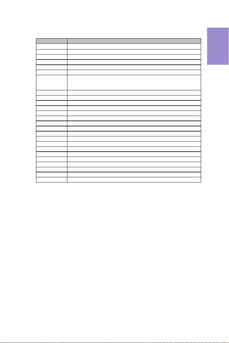
The manual consists of the following:
Describes features of the
motherboard.
H
page 1
Describes installation of
motherboard components.
H
page 7
H
page 27
H
page 49
Installing the Motherboard
Introducing the Motherboard
Provides information on us-
ing the BIOS Setup Utility.
Describes the motherboard
software.
Limits and methods of mesurement of radio disturbance char-
acteristics of information technology equipment
EN 55022
EN 61000-3-2
Disturbances in supply systems caused
EN 61000-3-3
Disturbances in supply systems caused by household appli-
ances and similar electrical equipment “ Voltage fluctuations”
EN 55024
Information technology equipment-Immunity characteristics-
Limits and methods of measurement
EN 60950
Safety for information technology equipment including electri-
cal business equipment
CE marking
About the Manual
This device is in conformity with the following EC/EMC directives:
Chapter 4
Chapter 1
Chapter 2
Chapter 3
Using BIOS
Using the Motherboard Software
Chapter 5
Trouble Shooting
Provides basic trouble shoot-
ing tips.
page 53
H

iii
H81H3-TI2 USER MANUAL
Chapter 2 7
Installing the Motherboard 7
Safety Precautions.............................................................................7
Installing the Motherboard in a Chassis......................................7
Checking Jumper Settings...........................................................8
Installing Hardware..................................................................10
Installing the Processor...........................................................10
Installing the CPU Cooler.........................................................12
Installing Memory Modules....................................................13
Installing Add-on Cards...........................................................14
Connecting Optional Devices..................................................16
Installing a Hard Disk Drive/Optical Disk Drive......................23
Connecting Case Components.......................................................24
TABLE OF CONTENTS
Preface i
Chapter 1 1
Introducing the Motherboard 1
Introduction...................................................................................1
Pakage Contents............................................................................1
Specifications................................................................................2
Motherboard Components..........................................................4
I/O Ports..............................................................................................6
Chapter 3 27
Using BIOS 27
About the Setup Utility........................ .......................................27
The Standard Configuration........................ ...........................27
Entering the Setup Utility.......................................................27
Resetting the Default CMOS Values.....................................28
Using BIOS........................................................................................28
BIOS Navigation Keys..............................................................29
Main Menu.............................................................................30
Advanced Menu......................................................................31
Chipset Menu..........................................................................41
Boot Menu..............................................................................44
Security Menu.........................................................................45
Exit Menu................................................................................46
Updating the BIOS.............................................................................47

iv
H81H3-TI2 USER MANUAL
Chapter 4 49
Using the Motherboard Software 49
Auto-installing under Windows 7/8.............................................49
Running Setup.........................................................................49
Manual Installation..........................................................................51
Chapter 5 53
Trouble Shooting 53
Start up problems during assembly..............................................53
Start up problems after prolong use............................................54
Maintenance and care tips..............................................................54
Basic Troubleshooting Flowchart...................................................55
1
H81H3-TI2 USER MANUAL
Chapter 1
Chapter 1
Introducing the Motherboard
Introduction
Thank you for choosing the H81H3-TI2 motherboard. This motherboard is a high
performance, enhanced function motherboard designed to support the LGA1150
socket for
Intel
®
4
th
Generation Core
TM
Family processors for high-end business or
personal desktop markets.
This motherboard is based on Intel
®
H81 Express Chipset for the best computer plat-
form solution. It supports up to 8 GB
of system memory with single channel DDR3
1600/1333/1066 MHz SO-DIMM. Two mini PCI Express slots are for extending usage.
It integrates USB 2.0 ports and USB 3.0 interface, supporting up to six USB 2.0 ports
(one 10-pin USB 2.0 header supports two USB 2.0 ports and three 5-pin USB 2.0 head-
ers support additional three USB 2.0 port and one USB 2.0 port at the rear panel) and
two USB 3.0 ports (two USB 3.0 ports at the rear panel).
This motherboard is equipped with advanced full set of I/O ports in the rear panel,
including one DC_IN port, one HDMI port, one USB 2.0 port, two USB 3.0 ports, one
RJ45 LAN connector, and audio jacks for line-out and mircophone.
In addition, this motherboard supports one SATA 6Gb/s and one SATA 3Gb/s connec-
tors for expansion.
Your motherboard package ships with the following items:
Package Contents
H81H3-TI2 Motherboard
User Manual
DVD
I/O Shield
1 SATA Cable and 1 SATA/Power Cable
Accessories may vary, please refer to actual goods you purchase.
Chapter 1
2
H81H3-TI2 USER MANUAL
Specifications
• Single-channel DDR3 memory architecture
• 1 x 204-pin DDR3 SO-DIMM socket supports up to 8 GB
• Supports DDR3 1600/1333/1066 MHz DDR3 SDRAM
Memory
• 2 x mini PCI Express slots
- mini PCIE1 (full-card) supports extension cards with SATA
signal, USB signal and PCIE signal.
- mini PCIE2 (half-card) supports extension cards with PCIE
signal & USB signal.
• Supported by Intel
®
H81 Express Chipset
- 1 x Serial ATA 3Gb/s device
- 1 x Serial ATA 6Gb/s device
Expansion
Slots
Storage
• 1 x 19V DC_IN port
• 1 x HDMI port
• 1 x USB 2.0 port
• 2 x USB 3.0 ports
• 1 x RJ45 LAN connector
• 1 x Audio port (1 x line-out, 1 x Microphone)
Rear Panel I/O
LAN • Realtek RTL8111G
- 10/100/1000 Fast Ethernet Controller
- Wake-on-LAN and remote wake-up support
• Realtek ALC662VD
- 6 Channel High Definition Audio Codec
- Compliant with HD audio specification
Audio
CPU
• Intel
®
H81 Chipset
Chipset
• LGA1150 socket for
Intel
®
4
th
Generation Core
TM
Family
processors
• VRD 12.5
• 1 x 4-pin CPU_FAN connector with smart fan function
• 1 x 4-pin SYS_FAN connector with smart fan function
• 1 x LDC header
• 1 x 10-pin USB 2.0 header supports additional two USB 2.0 ports
- 1 x 5-pin USB 2.0 header supports camera or other USB 2.0
device
- 1 x 5-pin USB 2.0 header supports card reader or other USB
2.0 device
- 1 x 5-pin USB 2.0 header (yellow) supports touch panel or other
• 1 x Serial ATA 6Gb/s connector
• 1 x Serial ATA 3Gb/s connector
• 1 x Case open header
• 1 x Front Panel switch/LED header
• 1 x Front Panel audio header
• 1 x Clear CMOS jumper
• 1 x SATA power connector
Internal I/O
Connectors &
Headers
USB 2.0 device

3
H81H3-TI2 USER MANUAL
Chapter 1
• AMI BIOS with 64Mb SPI Flash ROM
- Supports Plug and Play
- Supports ACPI & DMI
- Supports STR (S3) /STD (S4)
- Supports Hardware monitor
- Audio, LAN, can be disabled in BIOS
- F7 hot key for boot up devices option
- Supports EZ BIOS (1024 x 768 resolution, GUI UEFI)
- Supports Multi-Language
- Supports AC’97/HD Audio auto detect (default)
- LED Support: single color
System BIOS
• 1 x Speaker header (For All-In-One Specification)
• 1 x Consumer infrared header (CIR)
• 1 x Digital microphone header (For All-In-One Specification)
• 1 x LCD panel select jumper (For All-In-One Specification)
• 1 x LVDS connetor (For All-In-One Specification)
• 1 x LVDS brightness control header (For All-In-One Specifica-
tion)
• 1 x LVDS select jumper (For All-In-One Specification
Form Factor
• Thin Mini ITX Size, 170mm x 170mm
Bundled
Software/
Feature
• Supports Norton Anti Virus/Cyberlink Media Suite/Muzee
• 1 x LVDS brightness switch header (For All-In-One Specifica-
tion)
Chapter 1
4
H81H3-TI2 USER MANUAL
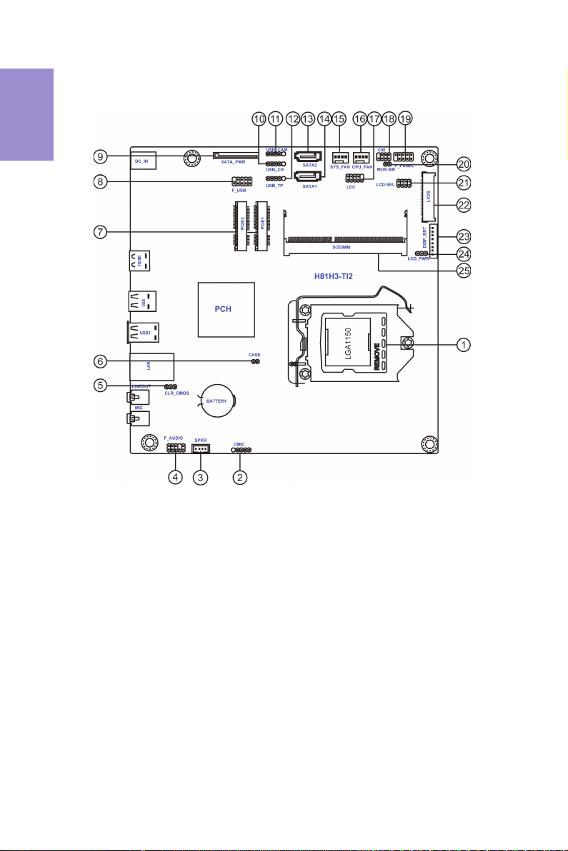
Motherboard Components
5
H81H3-TI2 USER MANUAL
Chapter 1
Table of Motherboard Components
LABEL COMP ONENTS
1. CPU Socket
LGA1150 socket for In tel® 4
th
Generation Core
TM
Family Processors
2. DMIC Digital microphone header (For All-In-One Specification)
3. SPKR Speaker header (For All-In-One Specification)
4. F_AUDIO Front panel audio header
5. CLR_CMOS Clear CMOS jumper
6. CASE Case open header
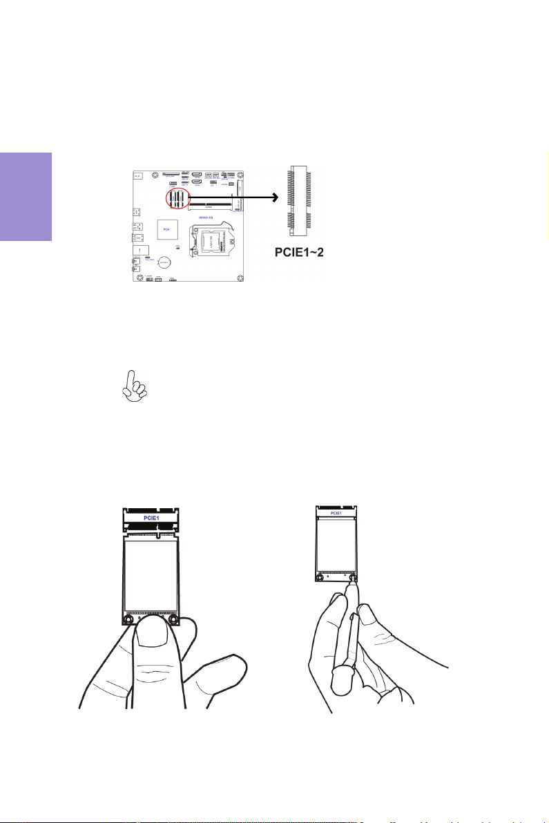
7. PCIE1~2
Mini PCI Express slots (mini PC IE1 (full-card) suppo rts extension cards with SATA
signal, USB signal and PCIE signal, and mini PCIE2 (half-card) supports extension
card s with PCIE signal & USB signal.)
8. F_USB Front panel USB 2.0 header
9. SATA_PWR SATA power connector
10. USB_CR 5-pin USB 2.0 h eader supports card reader or other USB 2.0 device
11. USB_CAM 5-pin USB 2.0 header supp orts camera or other USB 2.0 device
12. USB_TP 5-pin USB 2.0 header (yellow) supports touch panel or other USB 2.0 device
13. SATA2 Serial ATA 3Gb/s co nnector
14. SATA1 Serial ATA 6Gb/s co nnector
15. SYS_FAN 4-pin system coolin g fan connector with smart fan function
16. CPU_FAN 4-pin CPU cooling fan connector with smart fan function
17. LDC Debug card header
18. CIR Consumer infrared header
19. F_PANEL Front panel switch/LED header
20. MON_SW LVDS brightness switch header (For All-In-One Specification)
21. LCD_SEL LCD panel select jumper (For All-In-One Specification)
22. LVDS LVDS connector (For All-In-One Specification)
23. DISP_BRT LVDS brightness control header (For All-In-One Specification)
24. LCD_PWR LVDS select jumper (For All-In-One Specification)
25. SODIMM 204-pi n DDR3 SDRAM SO-DIMM
Chapter 1
6
H81H3-TI2 USER MANUAL
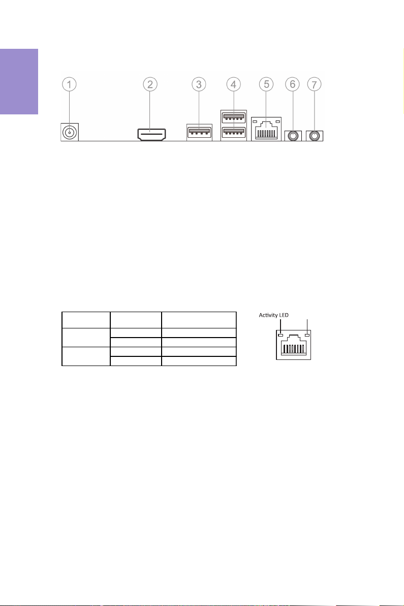
I/O Ports
1. 19V DC_IN Port
Connect the DC_IN port to the power adapter.
2.
HDMI Port
You can connect the display device to the HDMI port.
3. USB 2.0 Port
Use the USB 2.0 port to connect USB 2.0 device.
4. USB 3.0 Ports
Use the USB 3.0 ports to connect USB 3.0 devices.
5. LAN Port
Connect an RJ-45 jack to the LAN port to connect your computer to the Network.
6. Line-out (lime)
It is used to connect to speakers or headphones.
7. Microphone (pink)
It is used to connect to a microphone.
LAN LED Status Description
OFF No d ata
Orange blinking Active
OFF No link
Green Link
Activity LED
Link LED
Link LED
LAN Port

Chapter 2
7
H81H3-TI2 USER MANUAL
Chapter 2
Installing the Motherboard
2-1. Safety Precautions
2-2. Installing the motherboard in a Chassis
This motherboard carries a Thin Mini ITX form factor of 170 x 170 mm. Choose a
chassis that accommodates this form factor. Make sure that the I/O template in the
chassis matches the I/O ports installed on the rear edge of the motherboard. Most
system chassis have mounting brackets installed in the chassis, which corresponds
to the holes in the motherboard. Place the motherboard over the mounting brack-
ets and secure the motherboard onto the mounting brackets with screws.
Follow these safety precautions when installing the motherboard:
• Wear a grounding strap attached to a grounded device to avoid damage
from static electricity.
• Discharge static electricity by touching the metal case of a safely grounded
object before working on the motherboard.
• Leave components in the static-proof bags.
• Always remove the AC power by unplugging the power cord from the power
outlet before installing or removing the motherboard or other hardware
components.
Do not over-tighten the screws as this can stress the motherboard.
Chapter 2
8
H81H3-TI2 USER MANUAL
This section explains how to set jumpers for correct configuration of the
motherboard.
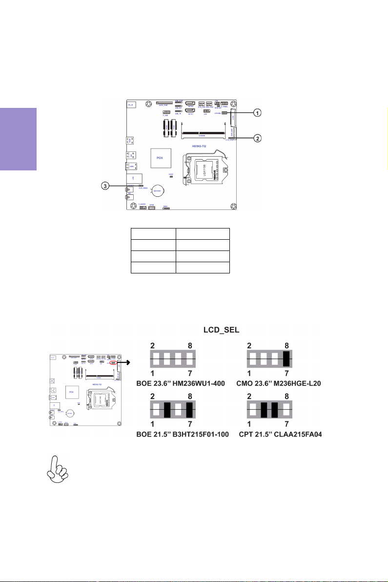
2-3. Checking Jumper Settings
1. LCD_SEL: LCD panel select header (For All-In-One Specification)
1.When your panel connects to LVDS, please check LCD_SEL header setting
first.
2.Due to the differences of the panel parameters, please follow the above
illustration to place the jumper caps.
No. Components
1LCD_SEL
2LCD_PWR
3CLR_CMOS
Chapter 2
9
H81H3-TI2 USER MANUAL
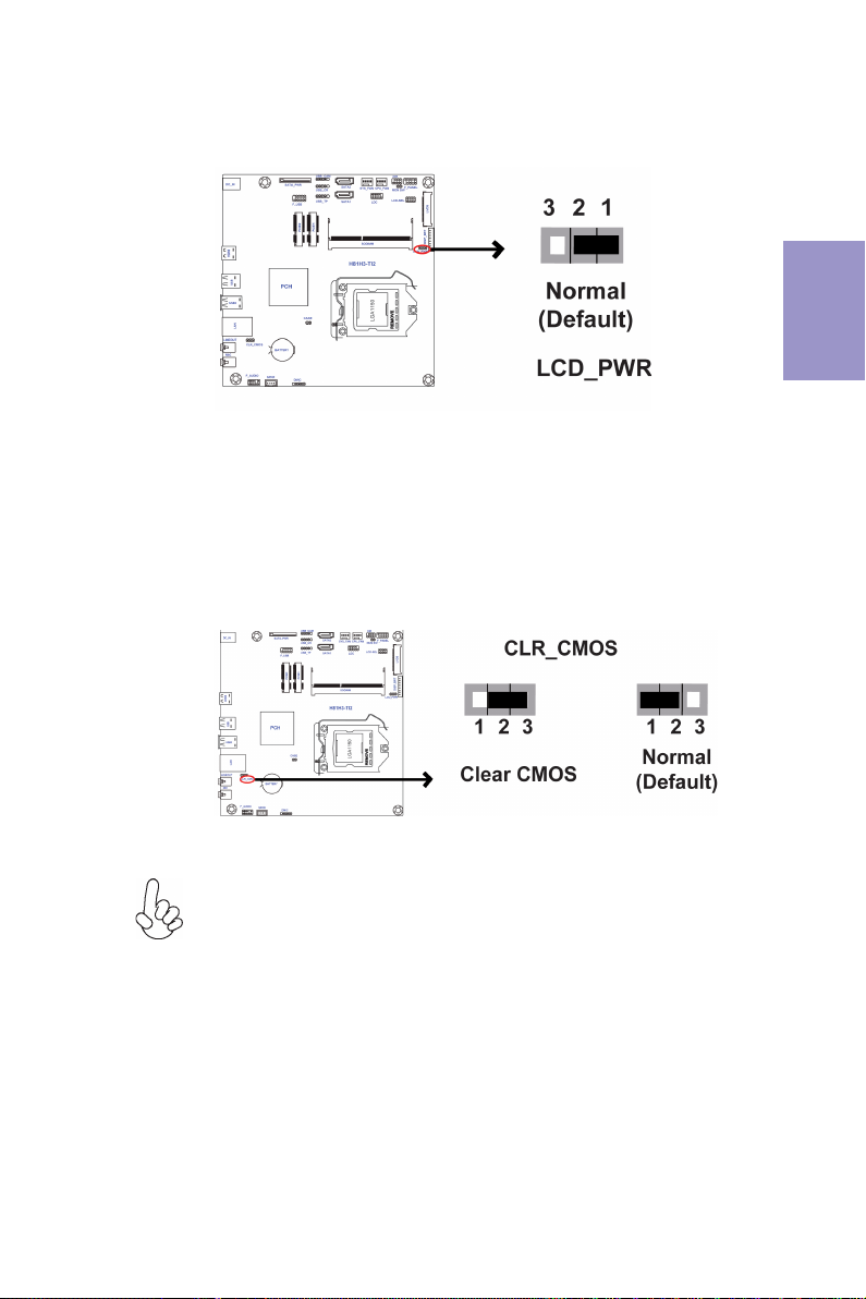
To avoid the system instability after clearing CMOS, we recommend users to
enter the main BIOS setting page to “Load Default Settings” and then “Save
and Exit Setup”.
The following illustration shows the location of the motherboard jumpers. Pin 1 is
labeled.
3. CLR_CMOS: Clear CMOS jumper
2. LCD_POWER: LVDS select header (For All-In-One Specification)
Chapter 2
10
H81H3-TI2 USER MANUAL
2-4. Installing Hardware
• This motherboard has an LGA1150 socket.
• When choosing a processor, consider the performance requirements of
the system. Performance is based on the processor design, the clock speed
and system bus frequency of the processor, and the quantity of internal
cache memory and external cache memory.
• You may be able to change the settings in the system Setup Utility. We
strongly recommend you do not over-clock processor or other
components to run faster than their rated speed.
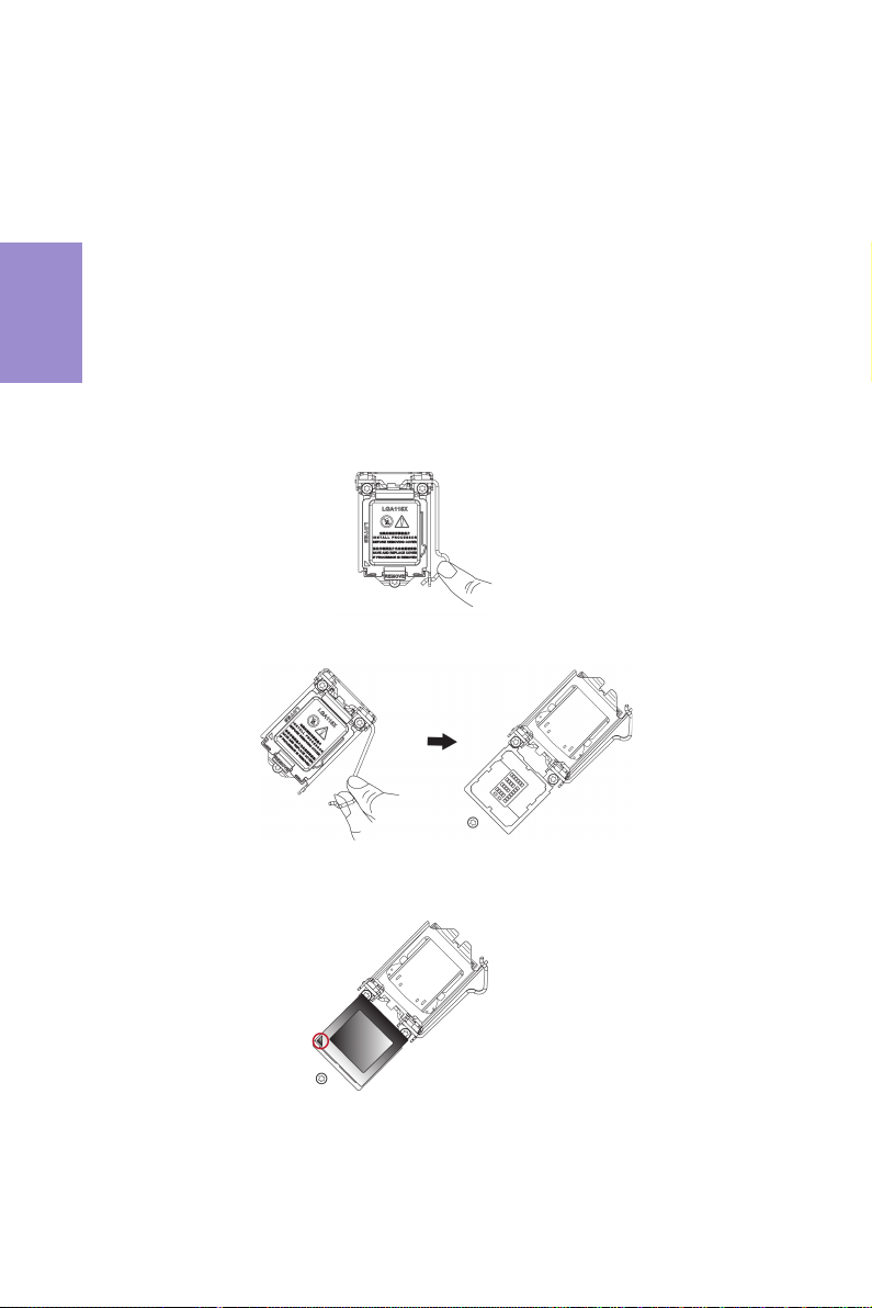
• The following illustration shows CPU installation components.
A. Press the hook of lever down with your thumb and pull it to the right
side to release it from retention tab.
B. Lift the tail of the load lever and rotate the load plate to fully open
position.
C. Grasp the edge of the package substrate. Make sure pin 1 indicator
is on your bottom-left side. Aim at the socket and place the package
carefully into the socket by purely vertical motion.
2-4-1. Installing the Processor
Chapter 2
11
H81H3-TI2 USER MANUAL
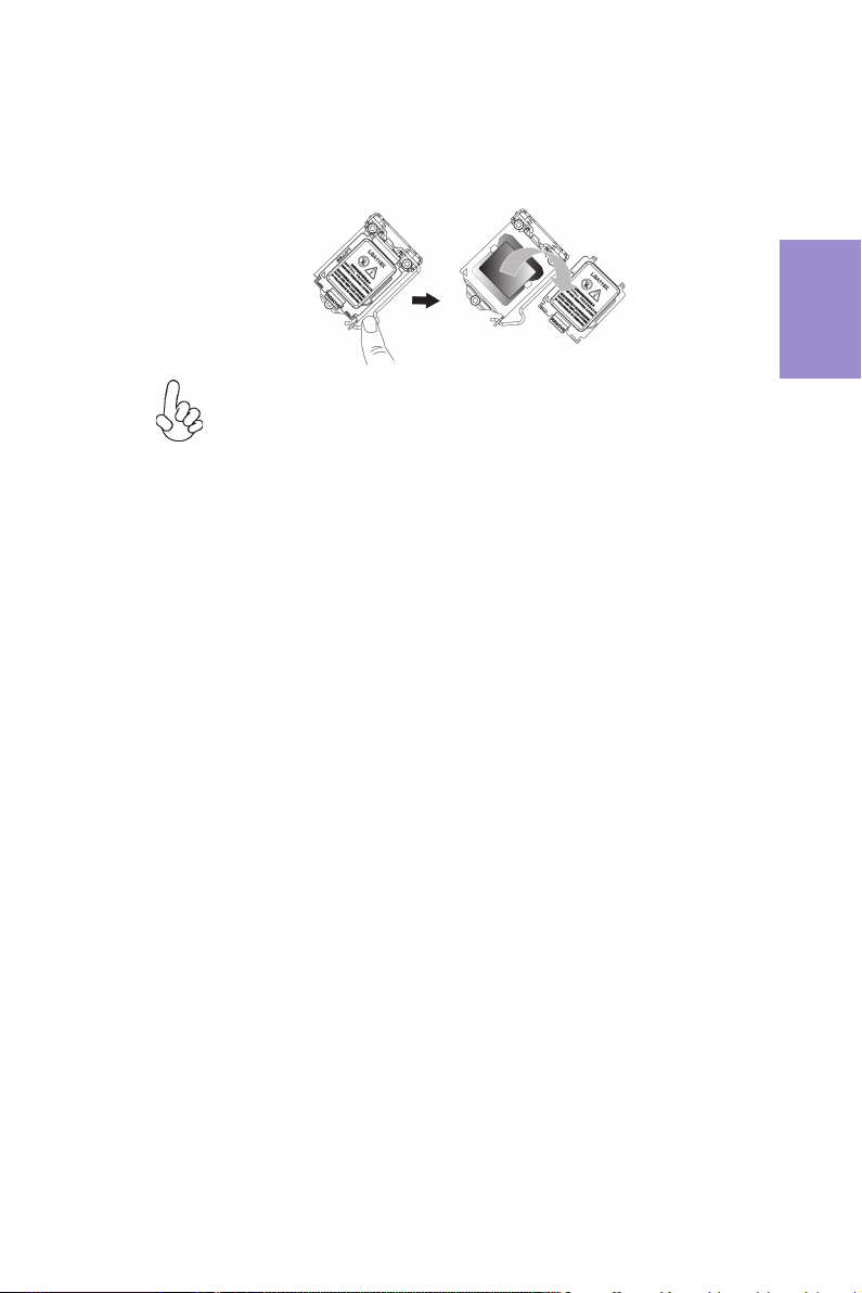
D. Rotate the load plate onto the package IHS (Intergraded Heat
Spreader). Engage the load lever while pressing down lightly onto the
load plate. Secure the load lever with the hook under retention tab. Then
the cover will flick automatically.
Please save and replace the cover onto the CPU socket if processor is re-
moved.
Chapter 2
12
H81H3-TI2 USER MANUAL
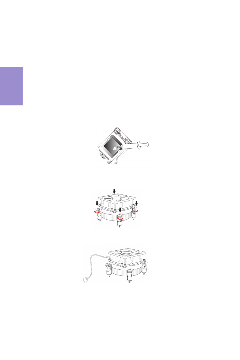
A. Apply some thermal grease onto the contacted area between the
heatsink and the CPU, and make it to be a thin layer.
B. Fasten the cooling fan supporting base onto the CPU socket on the
motherboard. And make sure the CPU fan is plugged to the CPU fan
connector.
C. Connect the CPU cooler power connector to the CPU_FAN connector.
2-4-2. Installing the CPU Cooler
• Install the cooling fan in a well-lit work area so that you can clearly see the
motherboard and processor socket.
• Avoid using cooling fans with sharp edges in case the fan casing and the
clips cause serious damage to the motherboard or its components.
• To achieve better airflow rates and heat dissipation, we suggest that you
use a high quality fan with 3800 rpm at least. CPU fan and heat sink
installation procedures may vary with the type of CPU fan/heatsink
supplied. The form and size of fan/heatsink may also vary.
• DO NOT remove the CPU cap from the socket before installing a CPU.
• Return Material Authorization (RMA) requests will be accepted only if the
motherboard comes with the cap on the LGA1150 socket.
• The following illustration shows how to install CPU fan.
Chapter 2
13
H81H3-TI2 USER MANUAL
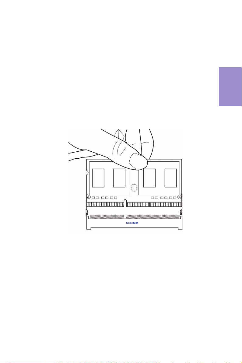
2-4-3. Installing Memory Modules
• This motherboard accommodates one memory module. It can supports
one 204-pin DDR3 1600/1333/1066 MHz.
• Do not remove any memory module from its antistatic packaging until
you are ready to install it on the motherboard. Handle the modules only
by their edges. Do not touch the components or metal parts. Always wear
a grounding strap when you handle the modules.
• You must install one module in the slot. Total memory capacity is 8 GB.
• Refer to the following to install the memory modules.
Install the DIMM module into the slot and press it firmly down until it fits
in place. Check that the cutouts on the DIMM module edge connector
match the notches in the DIMM slot.
Chapter 2
14
H81H3-TI2 USER MANUAL
2-4-4. Installing Add-on Cards
The slots on this motherboard are designed to hold expansion cards and connect
them to the system bus. Expansion slots are a means of adding or enhancing the
motherboard’s features and capabilities. With these efficient facilities, you can
increase the motherboard’s capabilities by adding hardware that performs tasks
that are not part of the basic system.
Before installing an add-on card, check the documentation for
the card carefully. If the card is not Plug and Play, you may have
to manually configure the card before installation.
PCIE1~2 Slots The mini PCIE1 (full-card) supports SATA signal, USB signal and
PCIe signal for extending usage of mSATA card and TV tuner card,
and mini PCIE2 (half-card) supports extension cards with PCIE
signal and USB signal.
Follow these instructions to install a mSATA card or TV tuner card:
1 Insert a Mini SATA (mSATA) card or TV tuner card into the PCIE1 Slot.
2 Lower the handle and tighten the screws.
 Loading...