


Disclaimer
The information in this document is subject to change without notice. The manufacturer makes no representations or warranties with respect to the contents hereof and specifically disclaims any implied warranties of merchantability or fitness for any particular purpose. The manufacturer reserves the right to revise this publication and to make changes from time to time in the content hereof without obligation of the manufacturer to notify any person of such revision or changes.
FederalCommunicationsCommission(FCC)
This equipment has been tested and found to comply with the limits for a Class B digital device, pursuant to Part 15 of the FCC Rules. These limits are designed to provide reasonable protection against harmful interference in a residential installation. This equipment generates, uses, and can radiate radio frequency energy and, if not installed and used in accordance with the instructions, may cause harmful interference to radio communications. However, there is no guarantee that interference will not occur in a particular installation. If this equipment does cause harmful interference to radio or television reception, which can be determined by turning the equipment off and on, the user is encouraged to try to correct the interference by one or more of the following measures:
•Reorient or relocate the receiving antenna
•Increase the separation between the equipment and the receiver
•Connect the equipment onto an outlet on a circuit different from that to which the receiver is connected
•Consult the dealer or an experienced radio/TV technician for help
Shielded interconnect cables and a shielded AC power cable must be employed with this equipment to ensure compliance with the pertinent RF emission limits governing this device. Changes or modifications not expressly approved by the system’s manufacturer could void the user’s authority to operate the equipment.
DeclarationofConformity
This device complies with part 15 of the FCC rules. Operation is subject to the following conditions:
•This device may not cause harmful interference.
•This device must accept any interference received, including interference that may cause undesired operation.
This device is in conformity with the following EC/EMC directives:
EN 55022
EN 61000-3-2
EN 61000-3-3
EN 55024
Limits and methods of mesurement of radio disturbance characteristics of information technology equipment
Disturbances in supply systems caused
Disturbances in supply systems caused by household appliances and similar electrical equipment “ Voltage fluctuations”
Information technology equipment-Immunity characteristicsLimits and methods of measurement
EN 60950 Safety for information technology equipment including electrical business equipment
CE marking
H81H3-M4 USER MANUAL

TABLE OF CONTENTS |
|
Preface |
i |
Brief Introduction |
1 |
Specifications...................................................................................... |
1 |
Motherboard Components................................................................ |
3 |
Header Pin Definition and Jumper Settings......................................... |
4 |
I/O Ports............................................................................................... |
6 |
Multi-language Quick Installation Guide |
7 |
English.................................................................................................. |
7 |
Brazilian Portuguese.......................................................................... |
9 |
Hindi.................................................................................................................... |
11 |
French...................................................................................................... |
13 |
Deutsch................................................................................................ |
15 |
Russian................................................................................................ |
17 |
Spanish................................................................................................ |
19 |
Indonesian............................................................................................. |
21 |
Arabic....................................................................................................... |
23 |
Simplified Chinese............................................................................... |
25 |
Korean...................................................................................................... |
27 |
H81H3-M4 USER MANUAL
ii
Brief Introduction
Specifications
CPU |
• |
LGA1150 socket for 4th Generation Intel→ CoreTM Family/ |
|
|
|
Pentium/Celeron Processors |
|
|
Note: Please go to ECS website for the latest CPU support list. |
||
|
|
|
|
Chipset |
• |
Intel→ H81 Chipset |
|
Memory |
• |
Dual-channel DDR3 memory architecture |
|
|
• |
2 x 240-pin DDR3 DIMM sockets support up to 16 GB |
|
|
• |
Supports DDR3 1600/1333 MHz DDR3 SDRAM |
|
|
|
|
|
Expansion |
• |
1 x PCI Express x16 Gen2 slot |
|
Slots |
|||
• |
1 x PCI Express x1 slot |
||
|
|||
|
|
|
|
Storage |
• |
Supported by Intel→ H81 Express Chipset |
|
|
|
- 2 x Serial ATA 6Gb/s devices, 2 x Serial ATA 3Gb/s devices |
|
|
|
|
|
Audio |
• |
VIA VT1705 |
|
|
|
- 6 Channel High Definiton Audio Codec |
|
|
|
- Compliant with HD audio specification |
|
|
|
|
|
LAN |
• |
Realtek RTL8111G Giga LAN(Colay 10/100) |
|
|
|
- 10/100/1000 Fast Ethernet Controller |
|
|
|
- Wake-on-LAN and remote wake-up support |
|
|
|
|
|
Rear Panel I/O |
• |
1 x PS/2 keyboard and PS/2 mouse connectors |
|
|
• |
1 x HDMI port |
|
|
• |
1 x VGA port |
|
|
• |
2 x USB 3.0 ports |
|
|
• |
1 x RJ45 LAN connector |
|
|
• |
2 x USB 2.0 ports |
|
|
• |
1 x Audio port (1x Line in, 1x Line out, 1x Mic_in Rear) |
|
|
|
|
|
Internal I/O |
• |
1 x 24-pin ATX_Power Supply connector |
|
Connectors & |
• |
1 x 4-pin ATX12V Power connector |
|
Headers |
• |
1 x 4-pin CPU_FAN connector |
|
|
• |
1 x 3-pin SYS_FAN connector |
|
|
• |
2 x USB 2.0 headers support additional four USB 2.0 ports |
|
|
• |
2 x Serial SATA 6Gb/s connectors |
|
|
• |
2 x Serial SATA 3Gb/s connectors |
|
|
• |
1 x COM header |
|
|
• |
1 x Case open header |
|
|
• |
1 x Front panel USB power select jumper |
|
|
• |
1 x LDC header |
|
|
• |
1 x Front Panel audio header |
|
|
• |
1 x Speaker header |
|
|
• |
1 x ME_UNLOCK header |
|
|
• |
1 x CLR_CMOS jumper |
|
|
|
|
|
H81H3-M4 USER MANUAL |
1 |

System BIOS |
• |
AMI BIOS with 64Mb SPI Flash ROM |
|
|
- Supports Plug and Play, STR(S3)/STD(S4) |
|
|
- Supports Hardware Monitor |
|
|
- Supports ACPI & DMI |
|
|
- Supports Audio, LAN, can be disabled in BIOS |
|
|
- F7 hot key for boot up devices option |
|
|
- Supports Pgup clear CMOS Hotkey (Has PS2 KB Model only) |
|
|
- Supports Dual Display |
|
|
- Supports EZ BIOS |
|
|
- Supports Multi-language |
|
|
- Supports AC’97/HD Audio auto detect (default) |
|
|
- Supports LOAD NON DISK UTILITY in BIOS BOOT Page |
Form Factor |
• |
190mm x 170mm |
|
|
|
QR Code for the complete manual download on ECS website: http://www.ecs.com.tw
2 |
H81H3-M4 USER MANUAL |
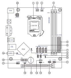
Motherboard Components
Table of Motherboard Components
LABEL |
COMPONENTS |
1. CPU Socket |
LGA1150 socket |
2. CPU_FAN |
4-pin CPU cooling fan connector |
3. SYS_FAN |
3-pin system cooling fan connector |
4. DDR3_1~2 |
240-pin DDR3 Module slots |
5. ATX_POWER |
Standard 24-pin ATX power connector |
6. SATA1~2 |
Serial ATA 6.0 Gb/s connectors |
7. SATA3~4 |
Serial ATA 3.0 Gb/s connectors |
8. CASE |
CASE open header |
9. F_USB1~2 |
Front panel USB 2.0 headers |
10. USBPWR_F |
Front panel USB power select jumper |
11. F_PANEL |
Front panel switch/LED header |
12. COM |
Onboard serial port header |
13. LDC |
Debug card header |
14. SPK |
Speaker header |
15. PCIEX16 |
PCI Express slot for graphics interface |
16. CLR CMOS |
Clear CMOS jumper |
17. F_AUDIO |
Front panel audio header |
18. PCIE1 |
PCI Express x1 slot |
19. ME_UNLOCK |
ME unlock header-for factory use only |
20. ATX12V |
4-pin +12V power connector |
H81H3-M4 USER MANUAL |
3 |

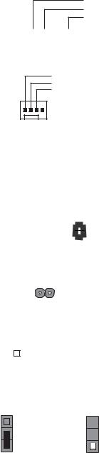
F_PANEL
PIN 1
MSG LED (+) |
PLED |
|
MSG LED (-) |
||
|
||
Power Switch (+) |
PWRBTN |
|
Power Switch (-) |
||
|
||
Reserved |
|
|
Reset Switch (+) |
RESET |
|
Reset Switch (-) |
||
|
||
Hard disk LED (-) |
HDLED |
|
Hard disk LED (+) |
||
|
F_AUDIO |
SENSE1_RETURN |
PRESENCE# |
AUD_GND |
PIN 1 |
Key
SENSE2_RETURN
PORT 1L |
|
|
|
|
|
PORT 2L |
PORT 1R |
|
|
|
|
|
SENSE_SEND |
|
|
|
|
|
||
|
PORT 2R |
|||||
COM
Serial Input |
Data Terminal Ready |
Data Set Ready |
Clear to Send |
PIN 1 |
Ring Indicator |
Request to Send |
Ground |
Serial Output |
Data Carrier Detect |
F_USB1~2 |
PIN 1
Power +5V

 Power +5V
USB Port A (-)


 USB Port B (-)
USB Port A (+)

 USB Port B (+)
Ground


 Ground
 Not Connected
LDC
LPC Signal |
LPC Signal |
LPC Signal |
LPC Signal |
Ground |
PIN 1 |
Power +3.3V
LPC signal
Reset
Clock
H81H3-M4 USER MANUAL
4
SPK
Signal
NC
VCC


 PIN 1
PIN 1
CPU_FAN
System Ground
Power +12V
Sensor
 PWM
PWM
1
SYS_FAN
|
|
|
|
|
|
|
|
|
|
|
|
|
System Ground |
|
||
|
|
|
|
|
|
|
|
|
|
|
|
|
Power +12V |
|
||
CASE |
|
|
|
1 |
|
|
|
|
|
|
Sensor |
|
||||
|
|
|
|
|
|
|
|
|
|
|||||||
|
|
|
|
|
|
|
|
|
|
|
|
|
||||
|
|
|
|
|
|
|
|
|
|
|
|
|
||||
|
|
|
|
|
|
|
|
|
|
|
|
|
||||
|
|
|
|
|
|
|
|
|
|
|
|
|
||||
|
|
|
|
|
|
|
|
|
|
|
|
|
||||
|
|
|
|
|
|
|
|
|
|
|
|
|
|
|
||
|
|
|
|
|
|
|
|
|
|
1 |
|
|
1 |
|
|
|
|
|
|
|
|
|
|
|
|
|
|
|
|
|
|
||
|
|
|
|
|
|
|
|
|
|
2 |
|
|
2 |
|
|
|
|
|
|
|
Chassis cover |
Chassis cover |
|
||||||||||
|
|
|
|
|
is removed |
is closed |
|
|||||||||
ME_UNLOCK |
|
|
|
|
|
|
|
|
||||||||
|
|
|
|
|
|
|
|
|
|
|
|
|
|
|||
|
|
|
|
|
|
|
|
|
|
|
|
|
|
|
|
|
|
|
|
|
|
|
|
|
|
|
|
|
|
|
|||
UNLOCK |
|
|
|
|
|
|
LOCK |
|
||||||||
CLR_CMOS Jumper |
|
|
|
|
||||||||||||
|
|
|
|
|
|
|
|
|
|
|
1-2: NORMAL |
|
||||
|
|
|
|
|
|
|
|
|
|
|||||||
|
|
|
|
|
|
|
|
|
|
|||||||
|
|
|
|
|
|
|
|
|
|
|
2-3: CLEAR CMOS |
|
||||
1 |
2 |
3 |
|
|||||||||||||
|
|
Before clearing the CMOS, make sure to turn off the system. |
||||||||||||||
|
CLR_CMOS |
|
|
|||||||||||||
|
|
|
|
|
|
|
|
|
||||||||
USBPWR_F (Front Panel USB Power Select Jumper) |
||||||||||||||||
|
|
|
|
|
3 |
|
|
|
|
|
|
3 |
|
|||
|
|
|
|
|
|
|
|
|
|
|
|
|||||
|
|
|
|
|
|
|
|
|
|
|
|
|||||
|
|
|
|
|
2 |
|
VCC |
|
|
2 |
5VSB |
|||||
|
|
|
|
|
|
|
||||||||||
|
|
|
|
|
|
|
||||||||||
|
|
|
|
|
|
|
|
|
|
(Default) |
|
|
|
|||
|
|
|
|
|
|
|
|
|
|
|
||||||
11
H81H3-M4 USER MANUAL
5
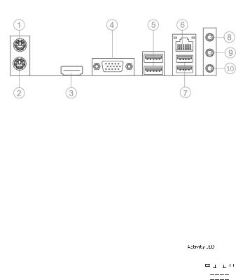
I/O Ports
1. PS/2 Mouse(green)
Use the upper PS/2 port to connect a PS/2 mouse.
2. PS/2 Keyboard(purple)
Use the lower PS/2 port to connect a PS/2 keyboard.
3. HDMI Port
You can connect the display device to the HDMI port.
4. VGA Port
Connect your monitor to the VGA port.
5. USB 3.0 Ports
Use the USB 3.0 ports to connect USB 2.0 devices.
6. LAN Port
Connect an RJ-45 jack to the LAN port to connect your computer to the Network.
|
|
|
|
|
|
|
|
|
|
|
|
Link LED |
|||||
LAN LED |
Status |
Description |
|||||||||||||||
|
|
|
|
|
|
|
|
|
|
|
|
|
|
||||
|
|
|
|
|
|
|
|
|
|
|
|
|
|
|
|
|
|
Activity LED |
OFF |
No data |
|
|
|
|
|
|
|
|
|
|
|
|
|
|
|
|
Orange blinking |
Active |
|
|
|
|
|
|
|
|
|
|
|
|
|
|
|
Link LED |
OFF |
No link |
|
|
|
|
|
|
|
|
|
|
|
|
|
|
|
|
|
|
|
|
|
|
|
|
|
|
|
|
|
||||
Green |
Link |
|
|
LAN Port |
|||||||||||||
|
|
|
|||||||||||||||
7. USB 2.0 Ports
Use the USB 2.0 ports to connect USB 2.0 devices.
8. Line-in(blue)
It can be connected to an external CD/DVD player, Tape player or other audio devices for audio input.
9. Line-out(lime)
It is used to connect to speakers or headphones.
10. Microphone(pink)
It is used to connect to a microphone.
6 |
H81H3-M4 USER MANUAL |
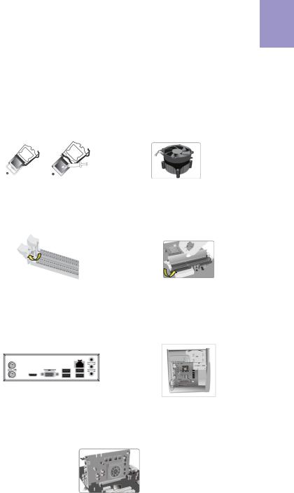
Hardware Installation Guide
Installation Steps
Step 1. Installation of the CPU and CPU Cooler:
1-1. Pull up the lever away from the |
1-2. Rotate and press down the fastener |
socket. Align the CPU cut edge with the |
of CPU fan to the motherboard through |
indented edge of the CPU socket. |
holes to install CPU fan into place. |
Gently place the CPU into correct |
|
position. Apply an even layer of thermal |
|
grease on the surface of CPU. |
|
English
Step 2. Installation of Memory Modules:
2-1. Unfasten the latches on each side of the DIMM slots.
2-2. Firmly press the DIMM down until it seats correctly. Make sure the slot latches are levered upwards and latch on the edge of the DIMM.
Step 3. Installation of Motherboard:
3-1. Replace the back I/O plate of the case with the I/O shield provided in motherboard’s package.
3-2. Place the motherboard within the case by positioning it into the I/O plate. Secure the motherboard to the case with screws.
Step 4. Installation of an Expansion card:
Remove the metal located on the slot and then insert the expansion card into the slot. Press the card firmly to make sure it is fully inserted into its slot. And then return the screw back to its position.
7
 Loading...