


Preface
Copyright
This publication, including all photographs, illustrations and software, is protected under international copyright laws, with all rights reserved. Neither this manual, nor any of the material contained herein, may be reproduced without written consent of the author.
Version 1.0
Disclaimer
The information in this document is subject to change without notice. The manufacturer makes no representations or warranties with respect to the contents hereof and specifically disclaims any implied warranties of merchantability or fitness for any particular purpose. The manufacturer reserves the right to revise this publication and to make changes from time to time in the content hereof without obligation of the manufacturer to notify any person of such revision or changes.
Trademark Recognition
Microsoft, MS-DOS and Windows are registered trademarks of Microsoft Corp.
AMD, Phenom, Athlon, Sempron and Duron are registered trademarks of AMD Corporation.
Other product names used in this manual are the properties of their respective owners and are acknowledged.
Federal Communications Commission (FCC)
This equipment has been tested and found to comply with the limits for a Class B digital device, pursuant to Part 15 of the FCC Rules. These limits are designed to provide reasonable protection against harmful interference in a residential installation. This equipment generates, uses, and can radiate radio frequency energy and, if not installed and used in accordance with the instructions, may cause harmful interference to radio communications. However, there is no guarantee that interference will not occur in a particular installation. If this equipment does cause harmful interference to radio or television reception, which can be determined by turning the equipment off and on, the user is encouraged to try to correct the interference by one or more of the following measures:
•Reorient or relocate the receiving antenna.
•Increase the separation between the equipment and the receiver.
•Connect the equipment onto an outlet on a circuit different from that to which the receiver is connected.
•Consult the dealer or an experienced radio/TV technician for help.
Shielded interconnect cables and a shielded AC power cable must be employed with this equipment to ensure compliance with the pertinent RF emission limits governing this device. Changes or modifications not expressly approved by the system’s manufacturer could void the user’s authority to operate the equipment.
Preface
ii
Declaration of Conformity
This device complies with part 15 of the FCC rules. Operation is subject to the following conditions:
•This device may not cause harmful interference, and
•This device must accept any interference received, including interference that may cause undesired operation.
Canadian Department of Communications
This class B digital apparatus meets all requirements of the Canadian Interferencecausing Equipment Regulations.
Cet appareil numérique de la classe B respecte toutes les exigences du Réglement sur le matériel brouilieur du Canada.
About the Manual
The manual consists of the following:
Chapter 1
Introducing the Motherboard
Chapter 2
Installing the Motherboard
Chapter 3
Using BIOS
Chapter 4
Using the Motherboard Software
Chapter 5
Hybrid Graphics® Technology
Support
Describes features of the motherboard. Go to H page 1
Describes installation of motherboard components.
Go to H page 7
Provides information on using the BIOS Setup Utility.
Go to H page 27
Describes the motherboard software
Go to H page 45
Describes the Hybrid Graphics®
Technology
Go to H page 55
Preface

iii
TABLE OF CONTENTS |
|
Preface |
i |
Chapter 1 |
1 |
Introducing the Motherboard |
1 |
Introduction............................................................................................ |
1 |
Features................................................................................................... |
2 |
Motherboard Components................................................................... |
4 |
Chapter 2 |
7 |
Installing the Motherboard |
7 |
Safety Precautions............................................................................. |
7 |
Choosing a Computer Case.............................................................. |
7 |
Installing the Motherboard in a Case.............................................7 |
|
Checking Jumper Settings................................................................ |
8 |
Setting Jumpers......................................................................... |
8 |
Checking Jumper Settings......................................................... |
9 |
Jumper Settings......................................................................... |
9 |
Installing Hardware.......................................................................... |
10 |
Installing the Processor........................................................... |
10 |
Installing Memory Modules..................................................... |
11 |
Expansion Slots....................................................................... |
15 |
Connecting Optional Devices.................................................. |
17 |
Installing a Hard Disk Drive/CD-ROM/SATA Hard Drive...... |
20 |
Installing a Floppy Diskette Drive........................................... |
21 |
Connecting I/O Devices.............................................................. |
22 |
Connecting Case Components......................................................23 |
|
Front Panel Header.................................................................. |
25 |
Chapter 3 |
27 |
Using BIOS |
27 |
About the Setup Utility.................................................................... |
27 |
The Standard Configuration.......................................................... |
27 |
Entering the Setup Utility............................................................... |
27 |
Using BIOS....................................................................................... |
28 |
Standard CMOS Setup.................................................................. |
29 |
Advanced Setup............................................................................. |
32 |
Advanced Chipset Setup................................................................ |
34 |
iv
Integrated Peripherals................................................................. |
35 |
Power Management Setup............................................................. |
36 |
PCI/PnP Setup.............................................................................. |
37 |
PC Health Status........................................................................... |
38 |
M.I.B (MB Intelligent Bios)........................................................... |
40 |
Load Default Settings.................................................................... |
42 |
Supervisor Password.................................................................... |
42 |
User Password.............................................................................. |
43 |
Save & Exit Setup ......................................................................... |
43 |
Exit Without Saving....................................................................... |
43 |
Updating the BIOS......................................................................... |
44 |
Chapter 4 |
45 |
Using the Motherboard Software |
45 |
About the Software CD-ROM......................................................... |
45 |
Auto-installing under Windows XP/Vista...................................... |
45 |
Running Setup............................................................................... |
46 |
Manual Installation.......................................................................... |
50 |
Utility Software Reference................................................................ |
50 |
Chapter 5 |
55 |
Hybrid Graphics® Technology Support |
55 |
Hybrid Graphics® Technology......................................................... |
55 |

1
Chapter 1
Introducing the Motherboard
Introduction
Thank you for choosing the A780GM-A Ultra motherboard. This motherboard is a high performance, enhanced function motherboard that supports socket for AMD PhenomTM processor (socket AM2+)/AthlonTM 64 X2 Dual-Core/AthlonTM 64/ SempronTM processors for high-end business or personal desktop markets.
The motherboard incorporates the AMD 780G Northbridge (NB) and SB750 Southbridge (SB) chipsets. The Northbridge supports the HyperTransportTM 3.0 interface. The memory controller supports DDR2 memory DIMM frequencies of 1066*1 (AM2+)/800/667/533/400. It supports four DDR2 slots with maximum memory size of 32 GB*2. One PCI Express x16 slot, intended for Graphics Interface, are fully compliant to the PCI Express Genaration 2.0 (version 2.0).
The SB750 Southbridge supports three PCI slots which are PCI 2.3 compliant. In addition, two PCI Express x1 slots are supported, fully compliant to the PCI Express Generation 2.0 (version 2.0). It integrates USB 2.0 interface, supporting up to twelve functional ports (six USB ports and three USB 2.0 headers support additional six USB ports). One onboard IDE connector supports two IDE devices in Ultra ATA 133/100/66/33 modes. The Southbridge integrates a Serial ATA host controller, supporting six SATA ports with maximum transfer rate up to 3.0 Gb/s each.
There is an advanced full set of I/O ports in the rear panel, including PS/2 mouse and keyboard connectors, one VGA port, one HDMI port, six USB ports, one ESATA port, one optical SPDIFO port, one LAN port and audio jacks for microphone, linein and 6/8-channel High Definition Audio output.
*1. Whether 1066 MHz memory speed is supported depends on the CPU being used.
2. Currently, the memory maximum size we have tested is 8 GB (2 GB per dimm).
Introducing the Motherboard

2
Feature
Processor
This motherboard uses a socket AM2+/AM2 that carries the following features:
•Accommodates AMD PhenomTM processor (socket AM2+)
AMD AthlonTM 64 X2 Dual-Core/AthlonTM 64/Sempron™ processors
•Supports HyperTransportTM (HT) 3.0 interface speeds
HyperTransportTM Technology is a point-to-point link between two devices, it enables integrated circuits to exchange information at much higher speeds than currently available interconnect technologies.
This board supports CPU up to 140W TDP only.
Chipset
The AMD 780G Northbridge (NB) and SB750 Southbridge (SB) chipsets are based on an innovative and scalable architecture with proven reliability and performance.
AMD 780G |
• |
One x4 A-Link Express II interface (PCI Express 1.1 |
|
(NB) |
|
compliant) for connection to an AMD Southbridge |
|
• |
Supports one PCI Express x16 for Graphics Interface, |
||
|
|||
|
|
fully compliant to the PCI Generation 2.0 (version 2.0). |
|
|
• |
Proven RadeonTM graphics powering DirectX®10 |
|
|
• |
Enhanced Digital Display integration |
|
|
• |
Fully ACPI 2.0, OnNow, and IAPC (Instantly Available |
|
|
|
PC) power management |
|
|
• |
Single chip solution in 55nm, 1.1 V CMOS technology |
|
|
• |
Integrated ATI Hybrid Graphics, ATI AvivoTM HD1, ATI |
|
|
|
PowerPlayTM, Low Power Design, AMD Cool’nQuietTM |
|
|
|
2.0, ATI SurroundViewTM, AMD OverDrive and AMD |
|
|
|
RAIDXpertTM |
|
SB750 |
• |
Compliant with PCI 2.3 specification at 33 MHz |
|
(SB) |
• |
Supports six Serial ATA devices which speeds up to 3.0 |
|
|
Gb/s |
||
|
|
||
|
• |
Complies with SATA 2.5 specification |
|
|
• |
Supports both SATA 1.5 and SATA3.0 compliance de- |
|
|
|
vices |
|
|
• |
Supports AHCI hardware assist to support advanced |
|
|
|
features such as NCQ ( Native Command Queuing), Hot |
|
|
|
Plug, and Device or Host initiated power Management |
|
|
|
(DIIPM/HIPM) |
|
|
• |
Integrated USB 2.0 Host Controller supporting up to |
|
|
|
twelve USB 2.0 ports |
|
|
• |
Integrated IDE controller supports Ultra ATA 133/100/66/ |
|
Memory |
|
33 modes |
|
|
|
•Supports DDR2 1066 (AM2+)/800/667 DDR SDRAM with Dualchannel architecture
•Accommodates four unbuffered DIMMs
•Up to 8 GB per DIMM with maximum memory size up to 32 GB*
Introducing the Motherboard

3
Audio
•All DACs support 192K/96K/48K/44.1KHz DAC sample rate
•High-quality analog differential CD input
•Software selectable 2.5V/3.75V VREFOUT
•Meets Microsoft WLP 3.08 audio requirements
•Direct Sound 3DTM compatible
Onboard LAN
•Supports PCI ExpressTM 1.1
•Integrated 10/100/1000 transceiver
•Wake-on-LAN and remote wake-up support
Expansion Options
The motherboard comes with the following expansion options:
•One PCI Express x16 for Graphics Interface
•Two PCI Express x1 slots
•Three 32-bit PCI v2.3 compliant slots
•One IDE connector supporting up to two IDE devices
•One floppy disk drive interface
•Six 7-pin SATA connectors
This motherboard supports Ultra DMA bus mastering with transfer rates of 133/100/66/33 MB/s.
Integrated I/O
The motherboard has a full set of I/O ports and connectors:
•Two PS/2 ports for mouse and keyboard
•One VGA port
•One HDMI port
•One ESATA port
•Six USB ports
•One LAN port
•One optical SPDIFO port
•Audio jacks for microphone, line-in and 6/8-channel High Definition
Audio output.
BIOS Firmware
The motherboard uses AMI BIOS that enables users to configure many system features including the following:
•Power management
•Wake-up alarms
•CPU parameters
•CPU and memory timing
The firmware can also be used to set parameters for different processor clock speeds.
1. Some hardware specifications and software items are subject to change without prior notice.
2. Due to chipset limitation, we recommend that motherboard be operated in the ambiance between 0 and 50°C.
Introducing the Motherboard

4
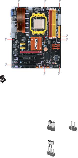
Motherboard Components
Introducing the Motherboard
5
Table of Motherboard Components
|
|
LABEL |
COMPONENTS |
|
1. |
CPU Socket |
Socket for AMD PhenomTM processor (socket AM2+)/ |
||
AthlonTM64 X2 Dual-Core/AthlonTM 64/SempronTM processors |
||||
|
|
|
||
2. |
CPU_FAN |
CPU cooling fan connector |
||
3. |
PWR_FAN2 |
Power cooling fan connector |
||
4. DDR2_1~4 |
240-pin DDR2 SDRAM slots |
|||
5. |
ATX_POWER |
Standard 24-pin ATX power connector |
||
6. |
IDE |
Primary IDE connector |
||
7. |
SPK |
Speaker header |
||
8. |
PWR_FAN1 |
Power cooling fan connector |
||
9. |
SATA1~6 |
Serial ATA connectors |
||
10. |
CLR_CMOS |
Clear CMOS jumper |
||
11. |
PWR_BTN |
Power on button |
||
12. |
RST_BTN |
Reset button |
||
13. |
F_PANEL |
Front panel switch/LED header |
||
14. SPI_DEBUG |
SPI DEBUG header |
|||
15. |
F_USB1~3 |
Front Panel USB headers |
||
16. |
FDD |
Floppy disk drive connector |
||
17. |
SPDIFO |
SPDIF out header |
||
18. |
F_AUDIO |
Front panel audio header |
||
19. |
PCI1~3 |
32-bit add-on card slots |
||
20. |
PCIEX16 |
PCI Express x16 slot for graphics interface |
||
21. |
PCIE1~2 |
PCI Express x1 slots |
||
22. |
SYS_FAN |
System cooling fan connector |
||
23. |
ATX12V |
8-pin +12V power connector |
||
This concludes Chapter 1. The next chapter explains how to install the motherboard.
Introducing the Motherboard
6
Memo
Introducing the Motherboard

7
Chapter 2
Installing the Motherboard
Safety Precautions
•Follow these safety precautions when installing the motherboard
•Wear a grounding strap attached to a grounded device to avoid damage from static electricity
•Discharge static electricity by touching the metal case of a safely grounded object before working on the motherboard
•Leave components in the static-proof bags they came in
•Hold all circuit boards by the edges. Do not bend circuit boards
Choosing a Computer Case
There are many types of computer cases on the market. The motherboard complies with the specifications for the ATX system case. Firstly, some features on the motherboard are implemented by cabling connectors on the motherboard to indicators and switches on the system case. Make sure that your case supports all the features required. Secondly, this motherboard supports one floppy diskette drive and two enhanced IDE drives. Make sure that your case has sufficient power and space for all drives that you intend to install.
Most cases have a choice of I/O templates in the rear panel. Make sure that the I/O template in the case matches the I/O ports installed on the rear edge of the motherboard.
This motherboard carries an ATX form factor of 305 X 244 mm. Choose a case that accommodates this form factor.
Installing the Motherboard in a Case
Refer to the following illustration and instructions for installing the motherboard in a case.
Most system cases have mounting brackets installed in the case, which correspond the holes in the motherboard. Place the motherboard over the mounting brackets and secure the motherboard onto the mounting brackets with screws.
Ensure that your case has an I/O template that supports the I/O ports and expansion slots on your motherboard.
Installing the Motherboard
8
Do not over-tighten the screws as this can stress the motherboard.
Checking Jumper Settings
This section explains how to set jumpers for correct configuration of the motherboard.
Setting Jumpers
Use the motherboard jumpers to set system configuration options. Jumpers with more than one pin are numbered. When setting the jumpers, ensure that the jumper caps are placed on the correct pins.
The illustrations show a 2-pin jumper. When |
|
|
the jumper cap is placed on both pins, the |
|
|
jumper is SHORT. If you remove the jumper |
|
|
cap, or place the jumper cap on just one pin, |
SHORT |
OPEN |
the jumper is OPEN. |
||
This illustration shows a 3-pin jumper. Pins |
|
|
1 and 2 are SHORT. |
|
|
Installing the Motherboard
9
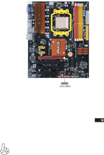
Checking Jumper Settings
The following illustration shows the location of the motherboard jumpers. Pin 1 is labeled.
Jumper Settings
Jumper |
Type |
Description |
Setting (default) |
|
|
|
|
|
|
|
|
|
|
|
1-2: NORMAL |
|
|
CLR_CMOS |
3-pin |
Clear CMOS |
2-3: CLEAR |
1 |
|
Before clearing the |
CLR_CMOS |
||||
|
|
|
|||
|
|
|
CMOS, make sure to |
|
|
|
|
|
turn off the system. |
|
To avoid the system unstability after clearing CMOS, we recommend users to enter the main BIOS setting page to “Load Default Settings” and then “Save Changes and Exit”.
Installing the Motherboard

10
Installing Hardware
Installing the Processor
Caution: When installing a CPU heatsink and cooling fan make sure that you DO NOT scratch the motherboard or any of the surfacemount resistors with the clip of the cooling fan. If the clip of the cooling fan scrapes across the motherboard, you may cause serious damage to the motherboard or its components.
On most motherboards, there are small surface-mount resistors near the processor socket, which may be damaged if the cooling fan is carelessly installed.
Avoid using cooling fans with sharp edges on the fan casing and the clips. Also, install the cooling fan in a well-lit work area so that you can clearly see the motherboard and processor socket.
Before installing the Processor
This motherboard automatically determines the CPU clock frequency and system bus frequency for the processor. You may be able to change the settings in the system Setup Utility. We strongly recommend that you do not over-clock processors or other components to run faster than their rated speed.
Warning:
1.Over-clocking components can adversely affect the reliability of the system and introduce errors into your system. Over-clocking can permanently damage the motherboard by generating excess heat in components that are run beyond the rated limits.
2.Always remove the AC power by unplugging the power cord from the power outlet before installing or removing the motherboard or other hardware components.
This motherboard has a socket AM2+/AM2 processor socket. When choosing a processor, consider the performance requirements of the system. Performance is based on the processor design, the clock speed and system bus frequency of the processor, and the quantity of internal cache memory and external cache memory.
Installing the Motherboard
11
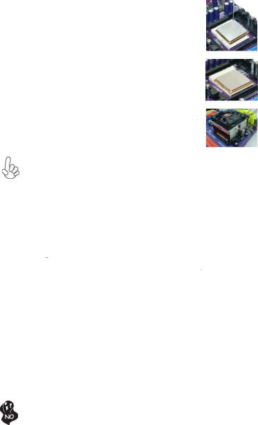
CPU Installation Procedure
The following illustration shows CPU installation components.
1Install your CPU. Pull up the lever away from the socket and lift up to 90-degree angle.
2Locate the CPU cut edge (the corner with the pin hold noticeably missing). Align and insert the CPU correctly.
3Press the lever down and apply thermal grease on top of the CPU.
4Put the CPU Fan down on the retention module and snap the four retention legs of the cooling fan into place.
5Flip the levers over to lock the heat sink in place and connect the CPU cooling Fan power cable to the CPUFAN connector. This completes the installation.
To achieve better airflow rates and heat dissipation, we suggest that you use a high quality fan with 4800 rpm at least. CPU fan and heatsink installation procedures may vary with the type of CPU fan/heatsink supplied. The form and size of fan/heatsink may also vary.
Installing Memory Modules
This motherboard accommodates four memory modules. It can support four 240-pin DDR2 1066 (AM2+)/800/667. The total memory capacity is 32 GB*.
DDR2 SDRAM memory module table
Memory module |
Memory Bus |
DDR2 667 |
333 MHz |
DDR2 800 |
400 MHz |
|
|
DDR2 1066 |
533 MHz |
|
|
You must install at least one module in any of the four slots. Each module can be installed with 8 GB of memory.
The four DDR2 memory sockets (DDR2_1, DDR2_2, DDR2_3, DDR2_4) are divided into two channels and each channel has two memory sockets as following:
ffChannel 0: DDR2_1, DDR2_2 ffChannel 1: DDR2_3, DDR2_4
Do not remove any memory module from its antistatic packaging until you are ready to install it on the motherboard. Handle the modules only by their edges. Do not touch the components or metal parts. Always wear a grounding strap when you handle the modules.
Installing the Motherboard
12
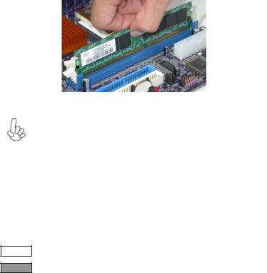
Installation Procedure
Refer to the following to install the memory modules.
1This motherboard supports unbuffered DDR2 SDRAM only.
2Push the latches on each side of the DIMM slot down.
3Align the memory module with the slot. The DIMM slots are keyed with notches and the DIMMs are keyed with cutouts so that they can only be installed correctly.
4Check that the cutouts on the DIMM module edge connector match the notches in the DIMM slot.
5Install the DIMM module into the slot and press it firmly down until it seats correctly. The slot latches are levered upwards and latch on to the edges of the DIMM.
6Install any remaining DIMM modules.
For best performance and compatibility, we recommend that users install DIMMs in the sequence of DIMM3, DIMM4, DIMM1 and
DIMM2.
Recommend configuration for best performance and compatibility
Number of DIMMs |
DIMM 1 |
DIMM 2 |
DIMM 3 |
DIMM 4 |
AM2 |
AM2+ * |
1 |
|
|
|
|
Single Channel |
Unganged Mode |
2 |
|
|
|
|
Dual Channel |
Ganged Mode |
3 |
|
|
|
|
Single Channel |
Unganged Mode |
4 |
|
|
|
|
Dual Channel |
Ganged Mode |
* When Unganged Mode is disabled
: operation with normal performance
: operation with the best performance
Installing the Motherboard

13
Table A: DDR2 (memory module) QVL (Qualified Vendor List)
The following DDR2 1066 (AM2+)/800/667 memory modules have been tested and qualified for use with this motherboard.
|
|
|
|
Type |
Size |
Vendor |
Module Name |
|
|
|
|
|
|
Apacer |
78.91G92.9K5 |
|
512 MB |
Micron |
MT4HTF6464AY-667E1 |
|
PSC |
AL6E8E63J-6E1 |
|
|
|
||
|
|
Ramxel |
R ML1520M38D6F-667 |
|
|
Samsung |
K4T51083QC |
|
|
Apacer |
78.01G9O.9K5 |
|
|
Elpida 1GB AM4B5708GEWS7E-0637F |
|
|
|
|
AU01GE667C5KBGC/Apacer/AM4B5708CPJS7E0810 |
|
|
|
C |
|
|
Corsair |
VS1GB667D2/Corsair/64M8CFEG QIB0900721 |
|
|
|
|
|
1 GB |
Hexon |
HYNT7AUDR-30M48 |
|
Kingston |
KVR667D2N5/RAmos/RC12T083CA6-53EC |
|
DDR2 667 |
|
Micron |
MT8HTF12864AY-667E1 |
|
PSC |
AL7E8E63B-6E1T |
|
|
|
||
|
|
AL7E8F63J-6E1 |
|
|
|
|
|
|
|
|
AL7E8F73C-6E1 |
|
|
Samsung |
Gold bar M378T2863DZS 0742/SEC/ZCE6 |
|
|
K4T1G084QD |
|
|
|
|
|
|
|
Aeneon |
AET860UD00-30DB08X |
|
|
Apacer |
78.A1G9O.9K4 |
|
|
Hexon |
HYNT8AUDR-30M88 |
|
2 GB |
Hynix |
HYMP125U64AP8-Y5-AB-A |
|
Kingston |
KVR667D2N5 |
|
|
|
||
|
|
LeadMax |
LD5PS1G831 |
|
|
PSC |
AL8E8F73C-6E1 |
|
|
Qimonda |
HYS64T256020EU-3S-C 2 |
|
|
|
|
Installing the Motherboard

14
|
|
Infineon |
HYS64T64020HU -2.5-A/Infineon/HYB18T256 800AF25 |
|
512 MB |
Kingston |
KVR800D2N5/512 |
|
Micron |
MT8HTF6464AY-80ED4 |
|
|
|
||
|
|
Qimonda |
HYS72T64000HU-2.5- |
|
|
B/Qimonda/HYB18T512800BF25 |
|
|
|
|
|
|
|
A-DATA |
M2GVD6G3I41P0U1E5E/A-DATA/VD29608A8D- |
|
|
25EG-E0722 |
|
|
|
|
|
|
|
Aeneon |
AET760UD00-25DC08X |
|
|
|
AET760UD00-30DB97X/Aeneon/AET93R250B 0725 |
|
|
|
AU01GE800C5KBGC/Apacer/AM4B5708JQJS8E0749 |
|
|
Apacer |
D |
|
|
|
78.01GA0.9K5 |
|
|
Geil |
Geil Millenary/Geil/GL2L64M088BA18H |
|
1 GB |
Hexon |
ELPT7AU DR-25M48 |
|
Kingston |
KHX6400D2ULK2/2G |
|
|
|
||
|
|
KVR 800D2N5/1G |
|
|
|
|
|
DDR2 800 |
|
Ramaxel |
RML1320EH38D7F-800/Elpida/E5108AHSE-8E-E |
|
0705098L1 |
||
|
|
Samsung |
Gold bar M378T2953EZ3-CE7 0726/SEC/ZCE7 |
|
|
K4T510830E |
|
|
|
|
|
|
|
Silicon |
SP001GBLRU800S01 |
|
|
Power |
|
|
|
|
|
|
|
Smart |
DM080818-HY1/Hynix/H Y5PS1G831CFP-S5 C822A |
|
|
Transcend |
Transcend/DIMM 5-5-5/Transcend/TQ123PGF8T0709 |
|
|
A-DATA |
Red A-DATA M2OMI6H3J4720L1C5Z/A-DATA/Boxed |
|
|
Aeneon |
AET860UD00-25DC08X |
|
|
Apacer |
78.A1GA0.9K4 |
|
|
CORSAIR |
CORSAIR/CM2X2048-6400C5/CORSAIR/Boxed |
|
|
Geil |
Platinum Edition/Geil/Boxed/2GB/DS |
|
2 GB |
Hexon |
ELPT8AU DR-25M88 |
|
Kingston |
KVR800D2N5 |
|
|
|
Micron |
MT16HTF25664AY-800E1 |
|
|
PSC |
AL8E8F73C-8E1 |
|
|
Qimonda |
HYS64T256020EU-25F-C2 |
|
|
Samsung |
M378T5663QZ3-CF7/SEC/HCF7 K4T1G084QQ/DS |
|
|
Silicon |
SP002GBLRU800S01 |
|
|
Power |
|
|
|
|
|
|
|
|
|
|
|
|
|
|
Type |
|
Size |
Vendor |
Module Name |
|
|
|
|
|
|
512 MB |
Kingston |
KVR1066D2N7/512 |
|
DDR2 1066 |
|
1 GB |
Kingston |
KVR1066D2N7/1G |
|
Qimonda |
HYB18T512800CF19F |
||
|
|
|
Micron |
MT8HTF12864AY-1GAE1 |
|
|
2 GB |
Micron |
DMT16HTF25664AY-1GAE1 |
1.Due to the Phenom CPU and memory module limitation, the DRAM may need to adjust the voltage for supporting DDR2 1066. The memory modules which can be used stably are listed in the above QVL table for
reference.
2.DDR2 1066 is supported when using socket AM2+ CPU.
Installing the Motherboard
 Loading...