


Preface
Copyright
This publication, including all photographs, illustrations and software, is protected under international copyright laws, with all rights reserved. Neither this manual, nor any of the material contained herein, may be reproduced without written consent of the author.
Version 1.0
Disclaimer
The information in this document is subject to change without notice. The manufacturer makes no representations or warranties with respect to the contents hereof and specifically disclaims any implied warranties of merchantability or fitness for any particular purpose. The manufacturer reserves the right to revise this publication and to make changes from time to time in the content hereof without obligation of the manufacturer to notify any person of such revision or changes.
Trademark Recognition
Microsoft, MS-DOS and Windows are registered trademarks of Microsoft Corp.
AMD, Phenom, Athlon, Sempron, Turion, and Duron are registered trademarks of AMD Corporation.
Other product names used in this manual are the properties of their respective owners and are acknowledged.
Federal Communications Commission (FCC)
This equipment has been tested and found to comply with the limits for a Class B digital device, pursuant to Part 15 of the FCC Rules. These limits are designed to provide reasonable protection against harmful interference in a residential installation. This equipment generates, uses, and can radiate radio frequency energy and, if not installed and used in accordance with the instructions, may cause harmful interference to radio communications. However, there is no guarantee that interference will not occur in a particular installation. If this equipment does cause harmful interference to radio or television reception, which can be determined by turning the equipment off and on, the user is encouraged to try to correct the interference by one or more of the following measures:
•Reorient or relocate the receiving antenna
•Increase the separation between the equipment and the receiver
•Connect the equipment onto an outlet on a circuit different from that to which the receiver is connected
•Consult the dealer or an experienced radio/TV technician for help
Shielded interconnect cables and a shielded AC power cable must be employed with this equipment to ensure compliance with the pertinent RF emission limits governing this device. Changes or modifications not expressly approved by the system’s manufacturer could void the user’s authority to operate the equipment.
A960M-MV USER MANUAL

Declaration of Conformity
This device complies with part 15 of the FCC rules. Operation is subject to the following conditions:
•This device may not cause harmful interference.
•This device must accept any interference received, including interference that may cause undesired operation.
This device is in conformity with the following EC/EMC directives:
EN 55022
EN 61000-3-2
EN 61000-3-3
EN 55024
EN 60950
CE marking
Limits and methods of mesurement of radio disturbance characteristics of information technology equipment
Disturbances in supply systems caused
Disturbances in supply systems caused by household appliances and similar electrical equipment “ Voltage fluctuations”
Information technology equipment-Immunity characteristicsLimits and methods of measurement
Safety for information technology equipment including electrical business equipment
Canadian Department of Communications
This class B digital apparatus meets all requirements of the Canadian Interferencecausing Equipment Regulations.
Cet appareil numérique de la classe B respecte toutes les exigences du Réglement sur le matériel brouilieur du Canada.
About the Manual
The manual consists of the following:
Chapter 1 |
Describes features of the |
Hpage 1 |
|
Introducing the Motherboard |
motherboard. |
|
|
Chapter 2 |
Provides information on us- |
Hpage |
7 |
Using BIOS |
ing the BIOS Setup Utility. |
|
|
Chapter 3 |
Describes the motherboard |
Hpage |
33 |
Using the Motherboard Software software.
Chapter 4
Trouble Shooting
Multi-language
Quick Installation Guide
Appendix
Provides |
basic trouble |
Hpage |
39 |
shooting tips. |
|
|
|
Describes |
installation of |
Hpage |
43 |
motherboard components. |
|
|
|
Provides header pin definitionHpage 77 and jumper settings.
ii
A960M-MV USER MANUAL

TABLE OF CONTENTS |
|
Preface |
i |
Chapter 1 |
1 |
Introducing the Motherboard |
1 |
Introduction........................................................................................... |
1 |
Pakage Contents.................................................................................. |
1 |
Specifications...................................................................................... |
2 |
Motherboard Components................................................................ |
4 |
I/O Ports............................................................................................... |
6 |
Chapter 2 |
7 |
Using BIOS |
7 |
About the Setup Utility........................................................................ |
7 |
The Standard Configuration........................ ............................ |
7 |
Entering the Setup Utility......................................................... |
7 |
Resetting the Default CMOS Values...................................... |
8 |
Using BIOS............................................................................................ |
8 |
BIOS Navigation Keys...............................................................9 |
|
Main Menu............................................................................... |
9 |
Advanced Menu...................................................................... |
10 |
Chipset Menu.......................................................................... |
20 |
M.I.B. III (MB Intelligent BIOS III) Menu.................................... |
22 |
Boot Menu............................................................................... |
27 |
Security Menu......................................................................... |
29 |
Exit Menu.................................................................................... |
30 |
Updating the BIOS...................................................................... |
31 |
Chapter 3 |
33 |
Using the Motherboard Software |
33 |
Auto-installing under Windows XP/7/8........................................ |
33 |
Running Setup........................................................................ |
33 |
Manual Installation.......................................................................... |
35 |
ECS Utility Software.......................................................................... |
35 |
Chapter 4 |
39 |
Trouble Shooting |
39 |
Start up problems during assembly.............................................. |
39 |
Start up problems after prolong use............................................ |
40 |
Maintenance and care tips.............................................................. |
40 |
Basic Troubleshooting Flowchart..................................................... |
41 |
A960M-MV USER MANUAL
iii
Multi-language Quick Installation Guide |
43 |
English.................................................................................................. |
43 |
Brazilian Portuguese...................................................................... |
46 |
Hindi..................................................................................................... |
49 |
French................................................................................................. |
52 |
Deutsch.................................................................................................. |
55 |
Russian................................................................................................ |
58 |
Spanish.................................................................................................... |
61 |
Indonesian.............................................................................................. |
64 |
Arabic................................................................................................ |
67 |
Simplified Chinese................................................................................. |
70 |
Korean................................................................................................... |
73 |
Appendix |
77 |
Header Pin Definition and Jumper Settings |
77 |
iv
A960M-MV USER MANUAL

Chapter 1
Introducing the Motherboard
Introduction
Thank you for choosing the A960M-MV motherboard. This motherboard is a high performance, enhanced function motherboard that supports socket AM3/AM3+ for AMD FXTM/PhenomTM II/AthlonTM II/SempronTM 100 series processors for high-end business or personal desktop markets.
The motherboard is based on AMD 760G (RS780L) Northbridge (NB) and SB710 Southbridge (SB) chipsets. The memory controller supports DDR3 memory DIMM frequencies of 1866(OC)/1600/1333/1066. It supports two DDR3 slots with maximum memory size of 16 GB. One PCI Express x16 slot, intended for Graphics Interface, is fully compliant to the PCI Express Gen2. In addition, one PCI Express x1 slot is supported.
The SB710 Southbridge integrates USB 2.0 interface, supporting up to eight USB 2.0 ports (four USB 2.0 ports at the rear panel and two USB 2.0 headers support additional four USB 2.0 ports). It also integrates a Serial ATA host controller, supporting four SATA ports with maximum transfer rate up to 3Gb/s each.
There is an advanced full set of I/O ports in the rear panel, including PS/2 mouse and keyboard connectors, four USB 2.0 ports, one LAN port, one D-sub (VGA) port, one HDMI port (optional) and audio jacks for microphone, line-in and line-out.
Package Contents
Your motherboard package ships with the following items:
A960M-MV Motherboard
User Manual
DVD
I/O Shield
2 SATA 3Gb/s Cables
The package contents above are for reference only, please take the actual package items as standard.
Chapter 1
A960M-MV USER MANUAL |
1 |
|

1 Chapter
Specifications
CPU |
• |
supports socket AM3/AM3+ for AMD FXTM/PhenomTM II/AthlonTM |
|
|
|
II/SempronTM 100 series processors |
|
|
• |
Supports CPU up to 95W TDP |
|
|
Note: Please go to ECS website for the latest CPU support list. |
||
|
|
|
|
Chipset |
• |
NB: AMD 760G |
|
|
|
SB: AMD SB710 |
|
|
|
|
|
Memory |
• |
Dual-channel DDR3 memory architecture |
|
|
• |
2 x 240-pin DDR3 DIMM sockets support up to 16 GB |
|
|
• |
Supports DDR3 1866(OC)/1600/1333/1066 MHz DDR3 SDRAM |
|
|
Note: Please go to ECS website for the latest memory support list. |
||
|
|
|
|
Expansion |
• |
1 |
x PCI Express x16 Gen2 slot |
Slots |
• |
1 |
x PCI Express x1 slot |
|
|
|
|
Storage |
• |
Supported by AMD SB710 Express Chipset |
|
|
|
- 4 x Serial ATA 3Gb/s connectors |
|
Audio |
• |
Realtek ALC 662 6 channel High Definition audio CODEC |
|
|
|
- Compliant with HD audio specification |
|
|
|
|
|
LAN |
• |
RTL8105E 10/100 LAN |
|
|
• |
RTL8111E Gigabit LAN (optional) |
|
|
|
|
|
Rear Panel I/O |
• |
1 |
x PS/2 keyboard and PS/2 mouse connectors |
|
• |
4 x USB 2.0 ports |
|
|
• |
1 x RJ45 LAN connector |
|
|
• |
1 |
x HDMI port (optional) |
|
• |
1 x D-sub (VGA) port |
|
|
• |
1 |
x Audio port (Line in, microphone and Line out) |
|
|
|
|
Internal I/O |
• |
1 x 24-pin ATX Power Supply connector |
|
Connectors & |
• |
1 x 4-pin 12V Power connector |
|
Headers |
• |
1 x 4-pin CPU_FAN connector |
|
|
• |
1 x 3-pin SYS_FAN connector |
|
|
• |
2 |
x USB 2.0 headers support additional four USB 2.0 ports |
|
• |
4 |
x Serial SATA 3Gb/s connectors |
|
• |
1 x COM header |
|
|
• |
1 x Case open header |
|
|
• |
1 |
x Front Panel audio header |
|
• |
1 |
x Front Panel switch/LED header |
|
• |
1 |
x Speaker header |
|
• |
1 x Clear CMOS jumper |
|
|
• |
1 x Front panel USB power select jumper |
|
|
• |
1 x Rear USB/PS2 power select jumper |
|
|
|
|
|
A960M-MV USER MANUAL
2

System BIOS |
• |
AMI BIOS with 16Mb SPI Flash ROM |
|
|
- Supports Plug and Play, S1/STR S3/STD S4 |
|
|
- Supports ACPI & DMI |
|
|
- Supports Hardware Monitor |
|
|
- Audio, LAN, can be disabled in BIOS |
|
|
- F7 hot key for boot up devices option |
|
|
- Supports Over-Clocking |
|
|
- Supports PaUp clear CMOS Hotkey (Has PS2 KB Model only) |
|
|
- Supports Dual Display |
|
|
- Supports UEFI BIOS |
|
|
- Supports AC’97/HD Audio auto detect |
|
|
|
AP Support |
• |
Supports eOC/eBLU*/eDLU/eSF* |
Note: *Microsoft .NET Framework 3.5 is required.
Form Factor |
• Micro ATX Size, 210mm x 180mm |
Chapter 1
A960M-MV USER MANUAL |
3 |
|

1 Chapter
Motherboard Components
A960M-MV USER MANUAL
4

Table of Motherboard Components
|
LABEL |
COMPONENTS |
|
1. CPU Socket |
supports socket AM3/AM3+ for AMD FXTM/PhenomTM II/ |
|
AthlonTM II/SempronTM 100 series processors |
|
|
|
|
|
2. CPU_FAN |
CPU cooling fan connector |
|
3. ATX_POWER |
Standard 24-pin ATX power connector |
|
4. DDR3_1~2 |
240-pin DDR3 SDRAM slots |
|
5. SYS_FAN |
System cooling fan connector |
|
6. SATA1~4 |
Serial ATA 3Gb/s connectors |
|
7. SPK |
Speaker header |
|
8. F_PANEL |
Front panel switch/LED header |
|
9. CLR_CMOS |
Clear CMOS jumper |
|
10. F_USB1~2 |
Front panel USB 2.0 headers |
|
11. USBPWR_F |
Front panel USB power select jumper |
|
12. COM |
Serial port header |
|
13. CASE |
Case open header |
|
14. F_AUDIO |
Front panel audio header |
|
15. PCIEX1 |
PCI Express x1 slots |
|
16. PCIEX16 |
PCI Express slot for graphics interface |
|
17. USBPWR_R |
Rear USB/PS2 power select jumper |
|
18. ATX12V |
4-pin +12V power connector |
|
|
|
Chapter 1
A960M-MV USER MANUAL |
5 |
|

1 Chapter
I/O Ports
1. PS/2 Mouse (green)
Use the upper PS/2 port to connect a PS/2 mouse.
2. PS/2 Keyboard (purple)
Use the lower PS/2 port to connect a PS/2 keyboard.
3. HDMI Port (Optional)
You can connect the display device to the HDMI port.
4. VGA Port
Connect your monitor to the VGA port.
5. USB 2.0 Ports
Use the USB 2.0 ports to connect USB 2.0 devices.
6. LAN Port
Connect an RJ-45 cable to the LAN port to connect your computer to the Network.
LAN LED |
Status |
Description |
|
|
|
|
|
|
|
|
|
Link LED |
||||
|
|
|
|
|
|
|
|
|
|
|
|
|
|
|||
|
|
|
|
|
|
|
|
|
|
|
|
|
|
|
|
|
Activity LED |
OFF |
No data |
|
|
|
|
|
|
|
|
|
|
|
|
|
|
|
Orange blinking |
Active |
|
|
|
|
|
|
|
|
|
|
|
|
|
|
Link LED |
OFF |
No link |
|
|
|
|
|
|
|
|
|
|
|
|
|
|
|
|
|
|
|
|
|
|
|
|
|
|
|
|
|||
Green |
Link |
|
|
|
|
|
|
|
|
|
|
|
|
|
|
|
|
|
|
LAN Port |
|||||||||||||
|
|
|
|
|
||||||||||||
7. Line-in (blue)
It can be connected to an external CD/DVD player, Tape player or other audio devices for audio input.
8. Line-out (lime)
It is used to connect to speakers or headphones.
9. Microphone (pink)
It is used to connect to a microphone.
A960M-MV USER MANUAL
6
Chapter 2
Using BIOS
About the Setup Utility
The computer uses the latest “American Megatrends Inc.” BIOS with support for Windows Plug and Play. The CMOS chip on the motherboard contains the ROM setup instructions for configuring the motherboard BIOS.
The BIOS (Basic Input and Output System) Setup Utility displays the system’s configuration status and provides you with options to set system parameters. The parameters are stored in battery-backed-up CMOS RAM that saves this information when the power is turned off. When the system is turned back on, the system is configured with the values you stored in CMOS.
The BIOS Setup Utility enables you to configure:
•Hard drives, diskette drives and peripherals
•Video display type and display options
•Password protection from unauthorized use
•Power Management features
The settings made in the Setup Utility affect how the computer performs. Before using the Setup Utility, ensure that you understand the Setup Utility options.
This chapter provides explanations for Setup Utility options.
The Standard Configuration
A standard configuration has already been set in the Setup Utility. However, we recommend that you read this chapter in case you need to make any changes in the future.
This Setup Utility should be used:
•when changing the system configuration
•when a configuration error is detected and you are prompted to make changes to the Setup Utility
•when trying to resolve IRQ conflicts
•when making changes to the Power Management configuration
•when changing the password or making other changes to the Security Setup
Entering the Setup Utility
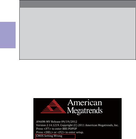
When you power on the system, BIOS enters the Power-On Self Test (POST) routines. POST is a series of built-in diagnostics performed by the BIOS. After the POST routines are completed, the following message appears:
Press DEL to enter SETUP
Chapter 2
A960M-MV USER MANUAL |
7 |
2 Chapter
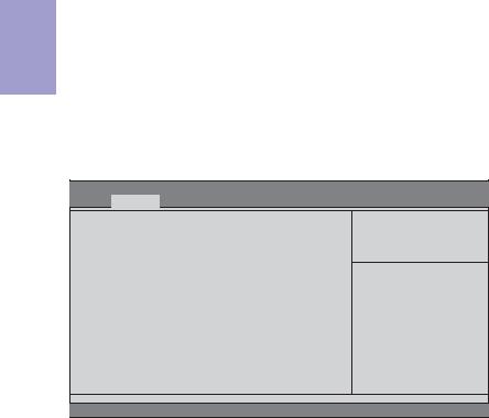
Press the delete key to access BIOS Setup Utility.
Aptio Setup Utility - Copyright (C) 2011 American Megatrends, Inc.
|
Main |
Advanced |
Chipset M.I.B. III Boot Security Exit |
|
|
|
|
|
|
BIOS Information |
|
Set the Date. Use Tab to switch |
||
|
|
|
|
between Data elements. |
System Data |
[Wed 09/19/2012] |
|
||
System Time |
[00:28:09] |
|
||
|
|
|
|
|
|
|
|
|
•k:Select Screen |
|
|
|
|
mn :Select Item |
|
|
|
|
Enter : Select |
|
|
|
|
+/- : Change Opt. |
|
|
|
|
F1:General Help |
|
|
|
|
F2:Previous Values |
|
|
|
|
F3:Optimized Defaults |
|
|
|
|
F4:Save & Exit |
|
|
|
|
ESC:Exit |
|
|
|
|
|
|
|
|
|
|
|
|
|
Version 2.14.1219. Copyright (C) 2011American Megatrends, Inc. |
|
|
|
|
|
|
Resetting the Default CMOS Values
When powering on for the first time, the POST screen may show a “CMOS Settings Wrong” message. This standard message will appear following a clear CMOS data at factory by the manufacturer. You simply need to Load Default Settings to reset the default CMOS values.
Note: Changes to system hardware such as different CPU, memories, etc. may also trigger this message.
Using BIOS
When you start the Setup Utility, the main menu appears. The main menu of the Setup Utility displays a list of the options that are available. A highlight indicates which option is currently selected. Use the cursor arrow keys to move the highlight to other options. When an option is highlighted, execute the option by pressing <Enter>.
Some options lead to pop-up dialog boxes that prompt you to verify that you wish to execute that option. Other options lead to dialog boxes that prompt you for information.
Some options (marked with a triangle f) lead to submenus that enable you to change the values for the option. Use the cursor arrow keys to scroll through the items in the submenu.
8 |
A960M-MV USER MANUAL |

In this manual, default values are enclosed in parenthesis. Submenu items are denoted by a triangle f.
The default BIOS setting for this motherboard apply for most conditions with optimum performance. We do not suggest users change the default values in the BIOS setup and take no responsibility to any damage caused by changing the BIOS settings.
BIOS Navigation Keys
The BIOS navigation keys are listed below:
KEY |
FUNCTION |
ESC |
Exits the current menu |
mn•k |
Scrolls through the items on a menu |
+/- |
Modifies the selected field’s values |
Enter |
Select |
|
|
F1 |
General Help |
F2 |
Previous Value |
|
|
F3 |
Optimized Defaults |
|
|
F4 |
Save & Exit |
|
|
For the purpose of better product maintenance, the manufacture reserves the right to change the BIOS items presented in this manual. The BIOS setup screens shown in this chapter are for reference only and may differ from the actual BIOS. Please visit the manufacture’s website for updated manual.
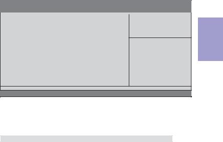
Main Menu
When you enter the BIOS Setup program, the main menu appears, giving you an overview of the basic system information. Select an item and press <Enter> to display the submenu.
Aptio Setup Utility - Copyright (C) 2011 American Megatrends, Inc.
|
Main |
Advanced |
Chipset M.I.B. III Boot Security Exit |
|
|
|
|
|
|
BIOS Information |
|
Set the Date. Use Tab to switch |
||
|
|
|
|
between Data elements. |
System Data |
[Wed 09/19/2012] |
|
||
System Time |
[00:28:09] |
|
||
|
|
|
|
|
|
|
|
|
•k:Select Screen |
|
|
|
|
mn :Select Item |
|
|
|
|
Enter : Select |
|
|
|
|
+/- : Change Opt. |
|
|
|
|
F1:General Help |
|
|
|
|
F2:Previous Values |
|
|
|
|
F3:Optimized Defaults |
|
|
|
|
F4:Save & Exit |
|
|
|
|
ESC:Exit |
|
|
|
|
|
|
|
|
|
|
|
|
|
Version 2.14.1219. Copyright (C) 2011American Megatrends, Inc. |
|
|
|
|
|
|
Chapter 2
A960M-MV USER MANUAL |
9 |
System Date & Time
The system Date and Time items show the current date and time on the computer. If you are running a Windows OS, these items are automatically updated whenever you make changes to the Windows Date and Time Properties utility.
2 Chapter
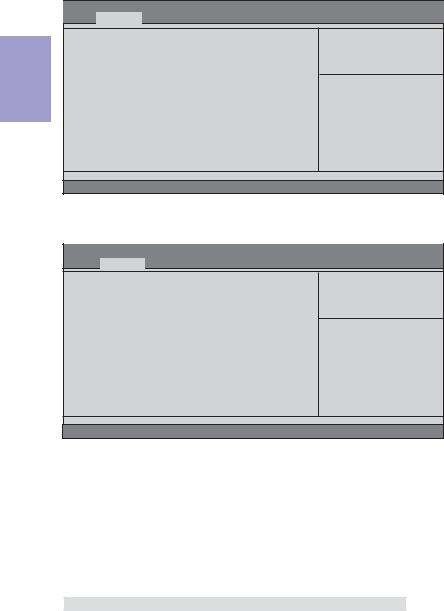
Advanced Menu
The Advanced menu items allow you to change the settings for the CPU and other system.
Aptio Setup Utility - Copyright (C) 2011 American Megatrends, Inc.
Main Advanced Chipset M.I.B. III Boot Security Exit
Legacy OpROM Support |
|
Launch PXE OpROM |
[Disabled] |
Launch Storage OpROM |
[Enabled] |
fLAN Configuration
fPC Health Status
fPower Management Setup
fACPI Settings
fCPU Configuration
fSATAConfiguration
fUSB Configuration
fSuper IO Configuration
Enable or Disable Boot Option for Legacy Network Devices.
•k:Select Screen mn :Select Item Enter : Select
+/- : Change Opt. F1:General Help F2:Previous Values F3:Optimized Defaults F4:Save & Exit ESC:Exit
Version 2.14.1219. Copyright (C) 2011American Megatrends, Inc.
Launch PXE OpROM (Disabled)
Use this item to enable or disable the PXE OpROM.
Launch Storage OpROM (Enabled)
Use this item to enable or disable the Storage OpROM.
10 |
A960M-MV USER MANUAL |
fLAN Configuration
The item in the menu shows the LAN-related information that the BIOS automatically detects.
Aptio Setup Utility - Copyright (C) 2011 American Megatrends, Inc.
Main |
Advanced |
Chipset |
M.I.B. III Boot |
Security Exit |
|
|
|
|
|
LAN Configuration |
|
|
||
Onboard LAN Controller |
[Enabled] |
|
||
•k:Select Screen mn :Select Item Enter : Select
+/- : Change Opt. F1:General Help F2:Previous Values F3:Optimized Defaults F4:Save & Exit ESC:Exit
Version 2.14.1219. Copyright (C) 2011American Megatrends, Inc.
Onboard LAN Controller (Enabled)
Use this item to enable or disable the Onboard LAN.
Press <Esc> to return to the Advanced Menu page.
Chapter 2
A960M-MV USER MANUAL |
11 |
2 Chapter
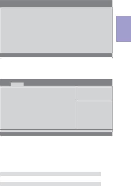
fPC Health Status
On motherboards support hardware monitoring, this item lets you monitor the paeameters for critical voltages, temperatures and fan speeds.
Aptio Setup Utility - Copyright (C) 2011 American Megatrends, Inc.
Main Advanced Chipset M.I.B. III Boot Security Exit
PC Health Status |
|
|
fSmart Fan Function |
|
|
CPU Tct1 |
: |
+47 |
CPU Fan Speed |
: |
5836 RPM |
CPU Voltage |
: |
+1.256V |
DIMM Voltage |
: |
+1.608V |
•k:Select Screen mn :Select Item Enter : Select
+/- : Change Opt. F1:General Help F2:Previous Values F3:Optimized Defaults F4:Save & Exit ESC:Exit
Version 2.14.1219. Copyright (C) 2011American Megatrends, Inc.
fSmart Fan Function
Scroll to this item and press <Enter> to view the following screen:
Aptio Setup Utility - Copyright (C) 2011 American Megatrends, Inc.
Main Advanced Chipset M.I.B. III Boot Security Exit
CPU Smart Fan Control |
[Enabled] |
Smart Fan Mode |
[Normal] |
High Limit Temperature(OC) |
60 |
Low Limit Temperature(OC) |
37 |
High Limit PWM |
200 |
Low Limit PWM |
56 |
•k:Select Screen mn :Select Item Enter : Select
+/- : Change Opt. F1:General Help F2:Previous Values F3:Optimized Defaults F4:Save & Exit ESC:Exit
Version 2.14.1219. Copyright (C) 2011American Megatrends, Inc.
CPU Smart Fan Control (Enabled)
This item allows you to enable/disable the control of the CPU fan speed by changing the fan voltage.
SMART Fan Mode (Normal)
This item allows you to select the fan mode (Normal, Quiet, Silent, or Manual) for a better operation environment. If you choose Normal mode, the fan speed will be auto adjusted depending on the CPU temperature. If you choose Quiet mode, the fan speed will be auto minimized for quiet environment. If you choose Silent mode, the fan speed will be auto restricted to make system more quietly. If you choose Manual mode, the fan speed will be adjust depending on users’ parameters.
Press <Esc> to return to the PC Health Status page.
12 |
A960M-MV USER MANUAL |

System Component Characteristics
These items display the monitoring of the overall inboard hardware health events, such as System & CPU temperature, CPU & DIMM voltage, CPU & system fan speed,... etc.
•CPU Tct1
•CPU Fan Speed
•CPU Voltage
•DIMM Voltage
Press <Esc> to return to the Advanced Menu page.
Chapter 2
A960M-MV USER MANUAL |
13 |

2 Chapter
fPower Management Setup
This page sets up some parameters for system power management operation.
Aptio Setup Utility - Copyright (C) 2011 American Megatrends, Inc. Main Advanced Chipset M.I.B. III Boot Security Exit
Power Management Setup |
|
Resume By RING |
[Disabled] |
Resume By PME |
[Disabled] |
Resume By USB 1.x/2.0 (S3) |
[Disabled] |
Resume By PS2 KB (S3) |
[Disabled] |
Resume By PS2 MS (S3) |
[Disabled] |
EUP Function |
[Enabled] |
Power LED Type |
[Dual Color LED] |
About Resume by USB Ring
•k:Select Screen mn :Select Item Enter : Select
+/- : Change Opt. F1:General Help F2:Previous Values F3:Optimized Defaults F4:Save & Exit ESC:Exit
Version 2.14.1219. Copyright (C) 2011American Megatrends, Inc.
Resume By RING (Disabled)
The system can be turned off with a software command. If you enable this item, the system can automatically resume if there is an incoming call on the Modem. You must use an ATX power supply in order to use this feature.
Resume By PME (Disabled)
This item is about resume by PCI/PCI-E/LAN/Ext.USB3.0 PME.
Resume By USB 1.x/2.0 (S3) (Disabled)
This item allows you to enable/disable the USB device wakeup function from S3 mode.
Resume By PS2 KB (S3) (Disabled)
This item enables or disables you to allow keyboard activity to awaken the system from power saving mode.
Resume By PS2 MS (S3) (Disabled)
This item enables or disables you to allow mouse activity to awaken the system from power saving mode.
EUP Support (Enabled)
This item allows user to enable or disable EUP support.
Power LED Type (Dual Color LED)
This item shows the type of the power LED.
Press <Esc> to return to the Advanced Menu page.
14 |
A960M-MV USER MANUAL |

fACPI Setting
The item in the menu shows the highest ACPI sleep state when the system enters suspend.
Aptio Setup Utility - Copyright (C) 2011 American Megatrends, Inc.
Main |
Advanced |
Chipset |
M.I.B. III Boot Security |
Exit |
|
ACPI Settings |
|
|
Select the highest ACPI sleep |
||
ACPI Sleep State |
[S3 (Suspend to RAM)] |
|
state the system will enter |
||
|
when the Suspend button is |
||||
|
|
|
|
|
pressed. |
|
|
|
|
|
|
|
|
|
|
|
•k:Select Screen |
|
|
|
|
|
mn :Select Item |
|
|
|
|
|
Enter : Select |
|
|
|
|
|
+/- : Change Opt. |
|
|
|
|
|
F1:General Help |
|
|
|
|
|
F2:Previous Values |
|
|
|
|
|
F3:Optimized Defaults |
|
|
|
|
|
F4:Save & Exit |
|
|
|
|
|
ESC:Exit |
|
|
|
|
|
|
Version 2.14.1219. Copyright (C) 2011American Megatrends, Inc.
ACPI Sleep State (S3(Suspend to RAM))
This item allows user to enter the ACPI S3 (Suspend to RAM) Sleep State (default).
Press <Esc> to return to the Advanced Menu page.
fCPU Configuration
Scroll to this item and press <Enter> to view the following screen:
Aptio Setup Utility - Copyright (C) 2011 American Megatrends, Inc. Main Advanced Chipset M.I.B. III Boot Security Exit
CPU Configuration
Socket0: AMD FX(tm)-6100 Six-Core Processor Max Speed: 3300 MHz Intended Speed:3300 MHz
Microcode Patch Level: 6000624
-- Information de cachette par noyau -- L1 Instruction Cache: 64 KB/2-way
L1 Data Cache: 16 KB/4-way
L2 Cache: 2048 KB/16-way Total L3 Cache per Socket: 8 MB/64-way
AMD C&Q |
[Enabled] |
Core Performance Boost |
[Enabled] |
Core C6 State |
[Enabled] |
Enhanced Halt (ClE) |
[Disabled] |
SB Clock Spread Spectrum |
[Disabled] |
Enable/Disable the AMD C&Q
Function.
•k:Select Screen mn :Select Item Enter : Select
+/- : Change Opt. F1:General Help F2:Previous Values F3:Optimized Defaults F4:Save & Exit ESC:Exit
Version 2.14.1219. Copyright (C) 2011American Megatrends, Inc.
Chapter 2
A960M-MV USER MANUAL |
15 |

2 Chapter
Socket0: AMD FX(tm)-6100 Six-Core Processor
This is display-only field and displays the information of the CPU installed in your computer.
Max/Intended Speed (3300 MHZ)
These items show the maximum/intended speed of the CPU.
Microcode Patch Level (6000624)
This item shows the Microcode revision.
L1 Instruction Cache (64 KB/2-way)
This item shows CPU L1 Cache.
L1 Data Cache (16 KB/4-way)
This item shows CPU L1 Cache.
L2 Cache (2048 KB/16-way)
This item shows CPU L2 Cache.
Total L3 Cache per Socket (8 MB/64-way)
This item shows CPU L3 Cache.
AMD C&Q (Enabled)
This item enables or disables the CPU C&Q Function.
Core Performance Boost (Enabled)
This item enables or disables the Core performance boost.
Core C6 State (Enabled)
This item enables or disables the Core C6 state.
Enhanced Halt (ClE) (Disabled)
Use this item to enable the CPU energy-saving function when the system is not running.
SB Clock Spread Spectrum (Disabled)
This item enables or disables the SB Clock Spread Spectrum.
Press <Esc> to return to the Advanced Menu page.
16 |
A960M-MV USER MANUAL |
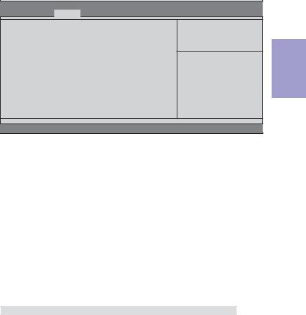
fSATA Configuration
Use this item to show the mode of serial SATA configuration options.
Aptio Setup Utility - Copyright (C) 2011 American Megatrends, Inc.
Main |
Advanced |
Chipset |
M.I.B. III Boot Security Exit |
|
|
|
|
|
|
SATAConfiguration |
|
Serial-ATA Controller |
||
|
|
|||
Serial-ATA Controller |
[Enhanced] |
|
||
SATAMode |
[IDE Mode] |
|
||
SATAPort1 |
Not Present |
|
||
SATAPort2 |
Not Present |
|
||
SATAPort3 |
Not Present |
|
||
SATAPort4 |
Not Present |
|
||
|
|
|
|
|
|
|
|
|
•k:Select Screen |
|
|
|
|
mn :Select Item |
|
|
|
|
Enter : Select |
|
|
|
|
+/- : Change Opt. |
|
|
|
|
F1:General Help |
|
|
|
|
F2:Previous Values |
|
|
|
|
F3:Optimized Defaults |
|
|
|
|
F4:Save & Exit |
|
|
|
|
ESC:Exit |
|
|
|
|
|
Version 2.14.1219. Copyright (C) 2011American Megatrends, Inc.
Serial-ATA Controller (Enhanced)
Use this item to select Serial-ATA controller options: Disabled, Compatible, Enhanced.
SATA Mode (IDE Mode)
Use this item to select SATA mode.
SATA Port 1~4 (Not Present)
This motherboard supports four SATA channel and each channel allows one SATA device to be installed. Use these items to configure each device on the SATA channel.
Press <Esc> to return to the Advanced Menu page.
Chapter 2
A960M-MV USER MANUAL |
17 |

2 Chapter
fUSB Configuration
Scroll to this item and press <Enter> to view the following screen:
Aptio Setup Utility - Copyright (C) 2011 American Megatrends, Inc.
Main |
Advanced |
Chipset |
M.I.B. III Boot Security Exit |
||
USB Configuration |
|
|
Enabled/Disabled All USB |
||
All USB Devices |
[Enabled] |
Devices |
|||
|
|||||
Legacy USB Support |
[Enabled] |
|
|||
|
|
|
|
|
|
|
|
|
|
|
•k:Select Screen |
|
|
|
|
|
mn :Select Item |
|
|
|
|
|
Enter : Select |
|
|
|
|
|
+/- : Change Opt. |
|
|
|
|
|
F1:General Help |
|
|
|
|
|
F2:Previous Values |
|
|
|
|
|
F3:Optimized Defaults |
|
|
|
|
|
F4:Save & Exit |
|
|
|
|
|
ESC:Exit |
|
|
|
|
|
|
Version 2.14.1219. Copyright (C) 2011American Megatrends, Inc.
All USB Devices (Enabled)
Use this item to enable or disable all USB devices.
Legacy USB Support (Enabled)
Use this item to enable or disable support for legacy USB devices. Setting to Audio allows the system to detect the presence of the USB device at startup. If detected, the USB controller legacy mode is enabled. If no USB device is detected, the legacy USB support is disabled.
Press <Esc> to return to the Advanced Menu page.
18 |
A960M-MV USER MANUAL |
fSuper IO Configuration
Use this item to show the information of the Super IO Configuration.
Aptio Setup Utility - Copyright (C) 2011 American Megatrends, Inc.
Main |
Advanced |
Chipset |
M.I.B. III Boot Security Exit |
||
Super IO Configuration |
|
|
Set Parameters of Serial Port |
||
|
|
|
|
|
0 (COMA) |
Super IO Chip |
F71808A |
|
|||
f Serial Port 0 Configutation |
|
|
|
||
|
|
•k:Select Screen |
|||
|
|
|
|
|
|
|
|
|
|
|
mn :Select Item |
|
|
|
|
|
Enter : Select |
|
|
|
|
|
+/- : Change Opt. |
|
|
|
|
|
F1:General Help |
|
|
|
|
|
F2:Previous Values |
|
|
|
|
|
F3:Optimized Defaults |
|
|
|
|
|
F4:Save & Exit |
|
|
|
|
|
ESC:Exit |
|
|
|
|
|
|
Version 2.14.1219. Copyright (C) 2011American Megatrends, Inc.
Super IO Chip (F71808A)
This item shows the information of the super IO chip.
fSerial Port 0 Configuration
Scroll to this item and press <Enter> to view the following screen:
Aptio Setup Utility - Copyright (C) 2011 American Megatrends, Inc.
Main Advanced Chipset M.I.B. III Boot Security Exit
Serial Port 0 Configuration |
|
Serial Port |
[Enabled] |
Device Settings |
Reset Required |
Change Settings |
[Auto] |
Enable or Disable Serial Port (COM)
•k:Select Screen mn :Select Item Enter : Select
+/- : Change Opt. F1:General Help F2:Previous Values F3:Optimized Defaults F4:Save & Exit ESC:Exit
Version 2.14.1219. Copyright (C) 2011American Megatrends, Inc.
Serial Port (Enabled)
This item allows you to enable or disable serial port.
Device Settings (Reset Required)
This item shows the information of the device settings.
Change Settings (Auto)
Use this item to change device settings.
Press <Esc> to return to the Super IO Configuration page.
Press <Esc> to return to the Advanced Menu page.
Chapter 2
A960M-MV USER MANUAL |
19 |

2 Chapter
Chipset Menu
The chipset menu items allow you to change the settings for the North Bridge chipset, South Bridge chipset and other system.
Aptio Setup Utility - Copyright (C) 2011 American Megatrends, Inc. Main Advanced Chipset M.I.B. III Boot Security Exit
fNorth Bridge
fSouth Bridge
North Bridge Parameters
•k:Select Screen mn :Select Item Enter : Select
+/- : Change Opt. F1:General Help F2:Previous Values F3:Optimized Defaults F4:Save & Exit ESC:Exit
Version 2.14.1219. Copyright (C) 2011American Megatrends, Inc.
fNorth Bridge
Scroll to this item and press <Enter> to view the following screen:
Aptio Setup Utility - Copyright (C) 2011 American Megatrends, Inc.
Main Advanced |
Chipset |
M.I.B. III Boot Security Exit |
|
|
|
North Chipset Configuration |
|
|
IGD Memory |
[Manual] |
|
UMA Frame Buffer Size |
[Auto] |
|
•k:Select Screen mn :Select Item Enter : Select
+/- : Change Opt. F1:General Help F2:Previous Values F3:Optimized Defaults F4:Save & Exit ESC:Exit
Version 2.14.1219. Copyright (C) 2011American Megatrends, Inc.
IGD Memory (Manual)
This item shows the information of the IGD (Internal Graphics Device) memory.
UMA Frame Buffer Size (Auto)
Use this item to adjust the share memory size of onboard VGA. This item only shows when IGD Memory set to manual.
Press <Esc> to return to the Chipset Menu page.
20 |
A960M-MV USER MANUAL |
fSouth Bridge
Scroll to this item and press <Enter> to view the following screen:
Aptio Setup Utility - Copyright (C) 2011 American Megatrends, Inc. Main Advanced Chipset M.I.B. III Boot Security Exit
South Bridge |
|
Restore AC Power Loss |
[Power Off] |
Audio Configuration |
|
Azalia Internal HDMI codec |
[Enabled] |
Azalia HD Audio |
[Enabled] |
Case Open Warning |
[Disabled] |
Chassis Opened |
[No] |
Specify what state to go to when power is re-applied after a power failure (G3 state).
•k:Select Screen mn :Select Item Enter : Select
+/- : Change Opt. F1:General Help F2:Previous Values F3:Optimized Defaults F4:Save & Exit ESC:Exit
Version 2.14.1219. Copyright (C) 2011American Megatrends, Inc.
Restore AC Power Loss (Power Off)
This item enables your computer to automatically restart or return to its operating status.
Audio Configuration
This item shows the information of the audio configuration.
Azalia Internal HDMI codec (Enabled)
This item enables or disables Azaia Internal HDMI codec.
Azalia HD Audio (Enabled)
This item enables or disables Azalia HD audio.
Case Open Warning (Disabled)
This item enables or disables the warning if the case is opened up, and the item below indicates the current status of the case.
Chassis Opened (No)
This item indicates whether the case has been opened.
Press <Esc> to return to the Chipset Menu page.
Chapter 2
A960M-MV USER MANUAL |
21 |
 Loading...