


Elica KIT02161, KIT02162, KIT02163, KIT02160, ECV630S3 Instructions
...Use, Care, and Installation Guide Guide d’utilisation, d’entretien et d’installation
Guía de instalación, uso y mantenimiento
READ AND SAVE THESE INSTRUCTIONS LISEZ CES INSTRUCTIONS ET CONSERVEZ-LES LEA Y GUARDE ESTAS INSTRUCCIONES
English |
Contents |
page |
2 |
French |
Sommaire |
page |
14 |
Spanish |
Contenido |
página |
26 |
English |
|
|
|
Contents |
|
|
|
Important safety Notice.............................................................................................................................................. |
|
3 |
|
Electrical & Installation requirements ...................................................................................................................... |
|
4 |
|
Electrical requirements |
........................................................................................................................................................................................ |
|
4 |
Before installing the hood .................................................................................................................................................................................... |
|
4 |
|
List of Materials........................................................................................................................................................... |
|
|
5 |
Parts supplied ...................................................................................................................................................................................................... |
|
|
5 |
Parts not supplied ................................................................................................................................................................................................ |
|
|
5 |
Dimensions and Clearances...................................................................................................................................... |
|
5 |
|
Ducting Options and .................................................................................................................................Examples |
|
6 |
|
Venting methods .................................................................................................................................................................................................. |
|
|
6 |
Preparation .......................................................................................................................................................................................................... |
|
|
6 |
Installation................................................................................................................................................................... |
|
|
7 |
Installation - Ducting version................................................................................................................................................................................ |
|
7 |
|
Description of the hood ..........................................................................................................................& Controls |
|
9 |
|
Controls................................................................................................................................................................................................................ |
|
|
9 |
Maintenance ................................................................................................................................................................ |
|
|
9 |
Cleaning................................................................................................................................................................................................................ |
|
|
9 |
Grease Filter ......................................................................................................................................................................................................... |
|
|
9 |
Replacing the light bulb........................................................................................................................................................................................ |
|
|
9 |
Warranty .................................................................................................................................................................... |
|
|
10 |
APPROVED FOR RESIDENTIAL APPLIANCES
FOR RESIDENTIAL USE ONLY
READ AND SAVE THESE INSTRUCTIONS
PLEASE READ ENTIRE INSTRUCTIONS BEFORE PROCEEDING. INSTALLATION MUST COMPLY WITH ALL LOCAL CODES.
IMPORTANT: Save these Instructions for the Local Electrical Inspector’s use. INSTALLER: Please leave these Instructions with this unit for the owner. OWNER: Please retain these instructions for future reference.
Safety Warning: Turn off power circuit at service panel and lock out panel, before wiring this appliance. Requirement: 120 V AC, 60 Hz. 15 or 20 A Branch Circuit
READ AND SAVE THESE INSTRUCTIONS
Important safety Notice
CAUTION
FOR GENERAL VENTILATING USE ONLY. DO NOT USE TO EXHAUST HAZARDOUS OR EXPLOSIVE MATERIALS OR VAPOURS.
WARNING
TO REDUCE THE RISK OF FIRE, ELECTRIC SHOCK, OR INJURY TO PERSONS, OBSERVE THE FOLLOWING:
A.Use this unit only in the manner intended by the manufacturer. If you have questions, contact the manufacturer.
B.Before servicing or cleaning the unit, switch power off at service panel and lock service panel disconnecting means to prevent power from being switched on accidentally. When the service disconnecting means cannot be locked, securely fasten a prominent warning device, such as a tag, to the service panel.
C.Installation Work and Electrical Wiring Must Be Done By Qualified Person(s) In Accordance With All Applicable Codes & Standards, Including Fire-rated Construction.
D.Sufficient air is needed for proper combustion and exhausting of gases through the flue (Chimney) of fuel burning equipment to prevent backdrafting. Follow the heating equipment manufacturers guideline and safety standards such as those published by the National Fire Protection Association (NFPA), the American Society for Heating, Refrigeration and Air Conditioning Engineers (ASHRAE), and the local code authorities.
E.When cutting or drilling into wall or ceiling, do not damage electrical wiring and other hidden utilities.
F.Ducted systems must always be vented to the outdoors.
CAUTION
To reduce risk of fire and to properly exhaust air, be sure to duct air outside - do not vent exhaust air into spaces within walls, ceilings, attics, crawl spaces, or garages.
WARNING
TO REDUCE THE RISK OF FIRE, USE ONLY METAL DUCT WORK.
Install this hood in accordance with all requirements specified.
WARNING
To Reduce The Risk Of Fire Or Electric Shock, Do Not Use This Hood With Any External Solid State Speed Control Device.
WARNING
TO REDUCE THE RISK OF A RANGE TOP GREASE FIRE.
a)Never leave surface units unattended at high settings. Boilovers cause smoking and greasy spillovers that may ignite. Heat oils slowly on low or medium settings.
b)Always turn hood ON when cooking at high heat or when flambeing food (I.e. Crepes Suzette, Cherries Jubilee, Peppercorn Beef Flambe’).
c)Clean ventilating fans frequently. Grease should not be allowed to accumulate on fan or filter.
d)Use proper pan size. Always use cookware appropriate for the size of the surface element.
WARNING
TO REDUCE THE RISK OF INJURY TO PERSONS, IN THE EVENT OF A RANGE TOP GREASE FIRE, OBSERVE THE FOLLOWING:
a)SMOTHER FLAMES with a close-fitting lid, cookie sheet, or other metal tray, then turn off the gas burner or the electric element. BE CAREFUL TO PREVENT BURNS. If the flames do not go out immediately, EVACUATE AND CALL THE FIRE DEPARTMENT.
b)NEVER PICK UP A FLAMING PAN - you may be burned.
c)DO NOT USE WATER, including wet dishcloths or towels - a violent steam explosion will result.
d)Use an extinguisher ONLY if:
1)You know you have a class ABC extinguisher, and you already know how to operate it.
2)The fire is small and contained in the area where it started.
3)The fire department is being called.
4)You can fight the fire with your back to an exit.
OPERATION
a. Always leave safety grills and filters in place. Without these components, operating blowers could catch onto hair, fingers and loose clothing.
The manufacturer declines all responsibility in the event of failure to observe the instructions given here for installation, maintenance and suitable use of the product. The manufacturer further declines all responsibility for injury due to negligence and the warranty of the unit automatically expires due to improper maintenance.
3
Electrical & Installation requirements
Electrical requirements
IMPORTANT
Observe all governing codes and ordinances.
It is the customer’s responsibility:
To contact a qualified electrical installer.
To assure that the electrical installation is adequate and in conformance with National Electrical Code, ANSI/NFPA 70
— latest edition*, or CSA Standards C22.1-94, Canadian Electrical Code, Part 1 and C22.2 No.0-M91 - latest edition** and all local codes and ordinances.
If codes permit and a separate ground wire is used, it is recommended that a qualified electrician determine that the ground path is adequate.
Do not ground to a gas pipe.
Check with a qualified electrician if you are not sure range hood is properly grounded.
Do not have a fuse in the neutral or ground circuit.
IMPORTANT
Save Installation Instructions for electrical inspector’s use.
The range hood must be connected with copper wire only.
The range hood should be connected directly to the fused disconnect (Or circuit breaker) box through metal electrical conduit.
Wire sizes must conform to the requirements of the National Electrical Code ANSI/NFPA 70 — latest edition*, or CSA Standards C22.1-94, Canadian Electrical Code Part 1 and C22.2 No. 0-M91 - latest edition** and all local codes and ordinances.
A U.L.- or C.S.A.-listed conduit connector must be provided at each end of the power supply conduit (at the range hood and at the junction box).
Copies of the standards listed may be obtained from:
* National Fire Protection Association Batterymarch Park Quincy,
Massachusetts 02269
** CSA International 8501 East Pleasant Valley Road Cleveland, Ohio 44131-5575
Before installing the hood
1.For the most efficient air flow exhaust, use a straight run or as few elbows as possible.
CAUTION: Vent unit to outside of building, only.
2.At least two people are necessary for installation.
3.Fittings material is provided to secure the hood to most types of walls/ceilings, consult a Qualified Installer, check if they perfectly fit with your cabinet/wall.
4.Do not use flex ducting.
5.COLD WEATHER installations should have an additional backdraft damper installed to minimize backward cold air flow and a nonmetallic thermal break to minimize conduction of outside temperatures as part of the ductwork. The damper should be on the cold air side of the thermal break.
The break should be as close as possible to where the ducting enters the heated portion of the house.
6.Make up air: Local building codes may require the use of Make-Up Air Systems when using Ducted Ventilation Systems greater than specified CFM of air movement. The specified CFM varies from locale to locale. Consult
your HVAC professional for specific requirements in your area.
Removing the packaging
CAUTION!
Remove carton carefully, Wear gloves to protect against sharp edges.
WARNING!
Remove the protective film covering the product before putting into operation.
4
List of Materials
Parts supplied
Removing the packaging
CAUTION!
Remove carton carefully, Wear gloves to protect against sharp edges.
WARNING!
Remove the protective film covering the product before putting into operation.
•Hood canopy assembly with blower.
•Lamp already installed.
•Transition (3 - 1/4” x 10” rectangular)
•Grease filter.
•Hardware bag with:
•Use, care and installation guide
•4x8 screws x 3 (to assemble Transition)
•4,5x13 screws x 6
•10x50 screws x 4
•1 Torx Adapter
Parts not supplied
Optional Accessories
•Duct Cover
•Backsplash kit
Tools/Materials required
•Wire nuts
•Tape to mount template
•Metal duct length to suit installation
•Measuring tape
•Pliers
•Gloves
•Knife
•Safety glasses
•Electric drill with 5/16” and 3/8” Bits
•Strain relief
•Spirit level
•Duct tape
•Screwdrivers:
Phillips (Posidrive) # 2 Torx # 2
•Wire cutter/stripper
•Masking tape
•Hammer
•Saw, jig saw or reciprocating saw
Dimensions and Clearances
2 "
"(6.5 cm)
(1.0 cm)
7½" (19.0 cm)
29 " (74.0 cm)
35 " (89.2 cm)
 12"
12"  (30.5 cm)
10" (25.4 cm)
2" (5.1 cm)
23" (58.4 cm)
30" (76.2 cm) 36" (91.4 cm)
5

Ducting Options and Examples
Closely follow the instructions set out in this manual.
All responsibility, for any eventual inconveniences, damages or fires caused by not complying with the instructions in this manual, is declined.
Venting methods
Vent Exhaust Option
The hood is designed for vertical or horizontal discharge.
Vertical discharge:
Use a rectangular duct 3 1/4” x 10”.
Horizontal discharge:
Use a rectangular duct 3 1/4” x 10”.
Preparation
Do not cut a joist or stud unless absolutely necessary. If a joist or stud must be cut, then a supporting frame must be constructed.
Fittings material is provided to secure the hood to most types of walls/ceilings.
However, a qualified technician must verify suitability of the materials in accordance with the type of wall/ceiling.
Before making cutouts, make sure there is proper clearance within the ceiling or wall for exhaust vent.
Hood installation height above cooktop is the users preference. The lower the hood is above the cooktop, the more efficient the capturing of cooking odors, grease and smoke.
CAUTION:
Mount this hood so that the bottom edge is at 30" (76.2 cm) minimum or 36"(91.4 cm) maximum above the cooking surface.
Household use, please, read installation manual for specific application.
Check your ceiling height and the hood height maximum before you select your hood.
6
Installation
Installation - Ducting version
After having chosen the vent option, proceed as follows:
•Prepare duct and conduit cut outs as needed.
•If possible, disconnect and move freestanding or slide-in range from cabinet opening to provide easier access to rear wall. Otherwise put a thick, protective covering over countertop, cooktop or range to protect from damage and debris. Select a flat surface for assembling the unit. Cover that surface with a protective covering and place all canopy hood parts and hardware in it.
•Determine and mark the centerline on the wall where the canopy hood will be installed.
• Select a mounting height comfortable for the user and mark on wall.
•Prepare duct and conduit cut outs as needed.
Remove the duct knockouts using a flat blade screwdriver and a small hammer.
Use the screwdriver by knocking out the pannel in similar fashion to a scalpel.
Take care of sharp edges.
Mark holes
Select the vent option that your installation will require and proceed to that section:
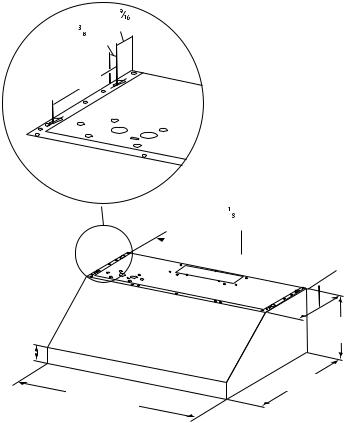
Outside top exhaust
(Vertical duct– 3 1/4”x 10” Rectangular)
Use the diagram or the hood as a template and mark the locations on the cabinet for ductwork, electrical wiring and keyhole screw slots.
Attach exhaust adaptor/damper over knockout opening with three exhaust adaptor screws. Make sure damper pivot is nearest to top/back edge of hood.
Remove tape from damper flap.
30” Model: 2-7/8” |
|
|
|
36” Model: 5-3/4” |
|
|
|
13/32” |
Cabinet front |
|
|
|
|
|
|
|
|
|
Hood mounting |
|
|
|
screws (4) |
|
5” |
5” |
Wood shims (recessed |
7-1/2” |
|
|
bottom cabinets only) |
7-7/8” |
Vertical duct |
3-1/4” |
|
|
access hole |
|
|
|
|
|
|
2-1/2” |
|
|
|
NOTE: The exhaust adaptor/damper can be installed up to 1 inch on either side of the hood center to accommodate offcenter ductwork. In extreme offcenter installations, one end of the duct connector may need to be trimmed to clear the electrical cable clamp.
Electrical access hole |
Center line |
5/8” |
(in cabinet bottom) |
|
|
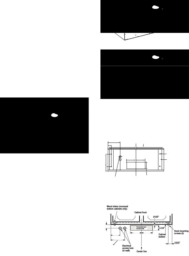
Outside rear exhaust
(Horizontal duct– 3 1/4”x 10” Rectangular)
• Use the diagram or the hood as a template and mark the locations on the cabinet for ductwork, electrical wiring and keyhole screw slots.
2-11/32”
5” 5”
30” Model: 4-15/32” 36” Model: 7” 
30” Model: 6-3/8”
36” Model: 8-7/8”
7
For recessed bottom cabinet only
If the cabinets have front, side or back trim, make 2 wood shims the width of the trim and attach them to the cabinet bottom recess on both sides.
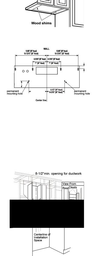
Installation to wall
(Horizontal duct– 3 1/4”x 10” Rectangular)
• Use the diagram or the hood as a template and mark the locations on the wall for ductwork, electrical wiring and keyhole screw slots.
21/32”
3”
10-5/8” |
|
10-5/8” |
|
||
(30” Model |
|
|
(30” Model |
|
|
|
|
|
|
||
36” Model) |
|
|
|
|
|
|
36” Model) |
|
|||
Install framing for hood support
•If drywall is present, mark the screw hole locations. Remove the template.
•Cut away enough drywall to expose 2 vertical studs at the holes location indicated by the template.
Install two horizontal supports at least 4" X 2" between two wall studs at the bottom and upper mounting holes installation location.
•The horizontal support must be flush with the room side of the studs.
Use cleats behind both sides of the support to secure to wall studs.
•Reinstall drywall and refinish.
IMPORTANTFraming must be capable of supporting 100 lbs.
Cut holes at marked locations for duct and electrical wiring. For the vertical duct, cut out 3/4” extra toward the front of the cabinet so you can move the duct freely when installing the hood.
It may also ease installation by cutting the hole 10 1/2” instead of 10”.
Drive a mounting screw (from the hardware packet) partway into each center of the narrow neck of the keyhole slots marked on the cabinet bottom.
Fix the wiring conduit to the hood.
Slide the hood back against the wall. Tighten the mounting screws. Be sure the screw heads are in the narrow neck of the keyhole slot.
Connect Ductwork to hood.
Electrical connection
WARNING
Electrical Shock Hazard
Warning: Turn off power circuit at the service panel before wiring this unit.
120 VAC, 15 or 20 Amp circuit required.
ELECTRICAL GROUNDING INSTRUCTIONS
THIS APPLIANCE IS FITTED WITH AN ELECTRICAL JUNCTION BOX WITH 3 WIRES, ONE OF WHICH (GREEN/YELLOW) SERVES TO GROUND THE APPLIANCE. TO PROTECT YOU AGAINST ELECTRIC SHOCK, THE GREEN AND YELLOW WIRE MUST BE CONNECTED TO THE GROUNDING WIRE IN YOUR HOME ELECTRICAL SYSTEM, AND IT MUST UNDER NO CIRCUMSTANCES BE CUT OR REMOVED.
Failure to do so can result in death or electrical shock.
Remove the knockout and the Junction box cover and install the conduit connector (cULus listed) in junction box.
Run 3 wires; black, white and green ,according to the National Electrical Code and local codes and ordinances, in 1/2" conduit from service panel to junction box.
Connect black wire from service panel to black or red in junction box, white to white and green to green-yellow.
Close and secure junction box cover.
Final installation step
Replace the 2 lateral supports.
Replace filters.
Check operation of the hood.
If range hood does not operate:
•Check that the circuit breaker is not tripped or the house fuse blown.
•Disconnect power supply. Check that wiring is correct.
To get the most efficient use from your new range hood, read the “Use and Care Information” section.
Keep your Installation Instructions and Use and Care Guide close to range hood for easy reference.
8

Description of the hood & Controls
2
1
3
4
5
1.Blower control switch
2.Light control switch
3.Lamp housings
4.Grease filter Handle
5.Grease filter
Controls
Use the high suction speed in cases of concentrated kitchen vapours. It is recommended that the cooker hood suction is switched on for 5 minutes prior to cooking and to leave in operation during cooking and for another 15 minutes approximately after terminating cooking.
Description of control panel
|
|
|
|
|
|
|
|
|
|
|
|
|
|
|
|
|
|
|
|
|
|
|
|
|
|
|
|
|
|
|
|
|
|
|
|
|
|
|
|
|
|
|
|
|
|
|
|
|
|
|
|
|
|
|
|
|
|
|
|
|
|
|
1 |
|
|
|
2 |
||||
1.Light Control
•Turn the light control from OFF to HI for the brightest light while cooking.
2.Fan Control
•Turn the fan control speed from OFF to HI as needed.
Maintenance
ATTENTION! Before performing any maintenance operation, isolate the hood from the electrical supply by switching off at the connector and removing the connector fuse.
Or if the appliance has been connected through a plug and socket, then the plug must be removed from the socket.
Cleaning
Do not spray cleaners directly to the control while cleaning the Hood.The cooker hood should be cleaned regularly (at least with the same frequency with which you carry out maintenance of the fat filters) internally and externally. Clean using the cloth dampened with neutral liquid detergent. Do not use abrasive products. DO NOT
USE ALCOHOL! WARNING:
Failure to carry out the basic cleaning recommendations of the cooker hood and replacement of the filters may cause fire risks.
Therefore, we recommend oserving these instructions.
The manufacturer declines all responsibility for any damage to the motor or any fire damage linked to inappropriate maintenance or failure to observe the above safety recommendations.
Grease Filter
To Remove Metal Grease Filters:
•Use 2 hands to remove the metal grease filters. Grasp filter handles, push toward the rear of the range hood and pull down on the front handle to remove.
•Repeat for each grease filter.
•Wash metal grease filters as needed in a dishwasher or hand wash in a hot detergent solution to clean.
To Reinstall Metal Grease Filters:
•Grasp filter handles and place rear of filter into rear track.
•Push down on the rear handle and set the front of the grease filter into the front track to secure.
•Repeat for each filter.
Replacing the light bulb
CAUTION
Before replacing the lamps, switch power off at service panel and lock service panel disconnecting means to prevent power from being switched on accidentally.
NOTE: Turn off the lights and fan. Allow the lights to cool before handling. If new lights do not operate be sure lights are inserted correctly before calling service.
 2
2
1
Replace Lights
•Remove the damaged light (twist counter clockwise) and replace with a new 120 Volt, 50 Watt (maximum) 50° halogen light made for a GU10 base, suitable for use in open luminarie.
9
 Loading...