


ENG Operating Instructions Spindle Moulder
F Instructions de service Fraiseuse de table
NO Bruksanvisning Bordfres
FIN Käyttöohje pöytäjyrsinkone
SV Handledning bänkfräsmaskin
TF 100 M
115 160 0294 / ENG/F/NO/FIN/SV / 3605 - 4.0
ENG
F
NO
FIN
SV
Attention! Carefully read through these instructions prior to installation and commissioning. Attention! Prière de lire attentivement la présente notice avant l'installation et la mise en service.
Se opp! Vær så vennlig å først gjennomlese nøyaktig denne veiledningen før installasjonen og idriftsettelsen. Huomio! Lue tämä ohje huolellisesti läpi ennen asennusta ja käyttöönottoa.
Observera! Var god och läs noga igenom denna handledning före installering och idrifttagande.

ENG
Contents |
|
11 |
Tool Dimensions/Cutting Speeds |
1 |
Specifications |
12 |
Jigs And Push Blocks |
2 |
User Responsibility |
13 |
Controls |
3 |
Standard Delivery |
13.1 |
Definitions |
4 |
Optional Accessories |
13.2 |
Mounting A Tool |
5 |
Final Assembly |
13.3 |
Spindle Speed Setting/Changing |
6 |
Installation |
13.4 |
Tool Height Setting |
7 |
Commissioning |
13.5 |
Fence And Fence Plate Setting |
7.1 |
1-Phase Power Supply |
13.6 |
Cutter Guard Setting |
7.2 |
3-Phase Power Supply |
14 |
Operation |
7.3 |
Direction Of Rotation |
14.1 |
Tools |
7.4 |
Switch |
14.2 |
Stock Prechecking |
7.5 |
Overload Protection |
14.3 |
Moulding Strips |
7.6 |
No-Voltage Release |
14.4 |
Moulding Boards |
7.7 |
Dust Collection |
14.5 |
Making Tenons |
7.8 |
Dust Collector Automatic Start |
14.6 |
Set-In Work |
8 |
Safety Information |
15 |
Care And Maintenance |
9Workpiece Dimensions
10Scope Of Application
1 Specifications |
TF 100 M 2.2 WN |
TF 100 M 2.8 DN |
Table top |
523 x 423 mm |
523 x 423 mm |
Workpiece support area |
150-210 x 600 mm |
150-210 x 600 mm |
Working height from floor |
850 mm |
850 mm |
Table opening Ø |
150 mm |
150 mm |
Table rings |
2 |
2 |
Fence travel |
30 mm |
30 mm |
Dust extraction outlet Ø |
100 mm |
100 mm |
Max. tool diameter |
150 mm |
150 mm |
Max. tool height |
60 mm |
60 mm |
Spindle diameter |
30 mm |
30 mm |
Spacing collar Ø |
50 mm |
50 mm |
Spindle vertical adjustment |
100 mm |
100 mm |
Spindle speeds |
4000/6000/7500 min-1 |
4000/6000/7500 min-1 |
Motor input capacity P1 |
2.2 kW S6 - 40% |
2.8 kW S6 - 40% |
Motor output capacity P2 |
1.1 kW S6 - 100% |
1.4 kW S6 - 100 % |
Operating voltage |
220-240 V 1~50 Hz |
380-415 V 3~50 Hz |
Noise Emission
The noise emission levels shown below have been established by measuring methods according to: DIN 45 635, part 1651.
The A-sound power levels (LWA) were rounded to full dB(A).
1. TF 100 operating under no load |
|
|
A-sound pressure level LpA |
77 dB(A) |
77 dB(A) |
A-sound power level LWA |
86 dB(A) |
86 dB(A) |
2. TF 100 operating under load |
|
|
A-sound pressure level LpA |
82 dB(A) |
82 dB(A) |
A-sound power level LWA |
91 dB(A) |
77 dB(A) |
2 User Responsibility
This machine will perform in conformity with the description contained in the instructions provided. This machine must be checked periodically. Defective equipment (including power cables) should not be used. Parts that are broken, missing, plainly worn, distorted or contaminated, should be replaced immediately. Should such repair or replacement become necessary, it is recommended that such repairs are carried out by qualified persons approved by metabo or its representatives.
This machine or any of its parts should not be altered or changed from standard specifications. The user of this machine shall have the sole responsibility for any malfunction which results from improper use or unauthorized modification from standard specifications, faulty maintenance, damage or improper repair by anyone other than qualified persons approved by metabo or its representatives.
Metabo reserves the right to change specifications and design without prior notice and without incurring obligation of any kind.
Equipment referred to as available or optional may be at extra cost.
3 |
Standard Accessories |
|
|
|
Spacing collars: |
1 pc. 25 mm, 1 pc. 16 mm, |
Fence plates |
|
|
2 pcs. 10 mm, 2 pcs. 8 mm, |
SUVA style safety cutter guard |
|
|
2 pcs. 5 mm |
Tool set |
|
Spindle nut: |
M 30x2 |
Instructions |
Fence
4 |
Optional Accessories |
|
|
|
Table Extension TF 100 |
Stock-no. 0914003598 |
|
|
Sliding Carriage TF 100 |
Stock-no. 0914015600 |
|
|
Moulding Tools |
see separate catalogue |
|
5 |
Final Assembly |
|
|
|
|
|
|
|
|
|
|
Set table extension level with the table. Install cutter guard carrier on the fence. |
Screw both stud bolts into the tapped |
|||
|
|
Use 4 each |
bore holes of the table. |
|
|
|
- hexagon head screw M 6x25 |
|
|
|
|
- hex. nut M 6 self-locking |
|
|
|
|
|
|
|
|
|
|
|
|
Place fence on table and screw |
Slide hexagon bar into fence carrier |
starknobs onto stud bolts. |
and lock with starknob screw. |
Install holddown shoe and spring on hexagon bar.
6 Installation
Important!
This spindle moulder model TF 100 M must be anchored to the floor for stability. A machine not anchored to the floor may fall over while in operation.
Use suitable means for anchoring, e.g. anchoring bolts or expansion anchors Ø 8 mm.
7 Commissioning
7.1 1-Phase Power Supply
This machine must be connected to an earthed outlet and operated on a residual current device (RCD) of 30 mA capacity. Supply voltage required 230V ±5% 50 Hz. Protect circuit with a fuse 16 A time-lag. A supply line lead cross section of min. 3 x 2.5 mm2 is required.
7.2 3-Phase Power Supply
A 5-wire (L1-L2-L3-N-Earth) supply system is required. Connect with the 16A CEE industrial type plug to an earthed outlet equipped with a residual current device (RCD) of 30 mA capacity. Supply voltage required 400V
±5% 50 Hz. Protect circuit with 3 fuses 16 A time-lag. A supply line lead cross section of min. 5 x 1.5 mm2 is required.
7.3 Direction Of Rotation
For machines with single-phase motor the direction of rotation is factory set. On machines with a three-phase motor the direction of rotation must be checked after connection to the power supply. Start motor briefly. The spindle, when viewed from the top, must turn counter-clockwise. To change the direction of rotation interchange 2 of the current conduction leads (black and/or brown). Do not connect the yellow-green earth lead to any of the current conducting leads.
Note:
With a wrong direction of rotation there is danger of accident. Check direction of rotation carefully. Have phases interchanged only by a qualified electrician!
7.4 Switch
This spindle moulder is started by actuating the green push-button and stopped by actuating the red button.
7.5 Overload Protection
In case of an overload the build-in motor protection relay switches the power off. Let motor cool off for approx. 10 minutes before starting again.
7.6 No-Voltage Release
The switch is equipped with a no-volt release solenoid (magnetic switch) to prevent start-up after a power failure. It the machine is not connected to the power supply the switch does not engage. In the event of a power failure the machine has to be restarted by switching ON again.
7.7 Dust Collection
This spindle moulder must be connected to a dust collector. - The fine dust of beech or oak is classified as cancer-causing.
The dust collector this spindle moulder is to be connected to must provide for a minimum air flow rate of 16 m/sec at the machine's dust extraction outlet.
The dust extraction outlet's nominal diameter is 100 mm.
7.8 Dust Collector Automatic Start
The electrical installation must provide for automatic starting of the dust collector when the spindle moulder is switched on, and for a 20 second switch-off delay after the spindle moulder is switched off.
8Safety Information
-Always follow the instructions in this manual.
-Use only tools approved for manual feed (BG-Test or similar).
-Never exceed the max. permissible tool speed.
-Follow the specific instructions supplied with the tool by the tool maker.
-Do not use tools of larger diameter than specified for this machine.
-Do not work stock with smaller or larger dimensions than specified in this manual.
-Always disconnect from power before servicing.
-Always let the spindle come to a complete stop before removing any obstructions.
-Fence, fence plates and cutter guard have to be set as required for the job on hand.
-Always feed strips and other small workpieces with a pushstick or pushblock.
-Select a suitable spindle speed (see section 11.0 of this manual).
-Persons under the age of 16 should not operate this machine.
-Ensure you know how to switch off the machine in an emergency.
-Always wear eye protection.
9Workpiece Dimensions
-Workpieces shorter than 200 mm must not be worked on this spindle moulder unless a suitable feeding jig is used for support.
-Support workpieces longer than 1000 mm with table extensions (optional accessory) or roller stands to keep them from falling off the machine's table.
-The maximum workpiece width (for boards) should not exceed 500 mm.
10Scope Of Application
-The Spindle Moulder model TF 100 M is designed for moulding workpieces of timber and/or timber derived products, e.g. chip or particle board, fibre boards and plywood, either plain or laminated/faced with plastics.
-Moulding on endgrain, e.g. making tenons, requires a sliding carriage (optional accessory) for firm guiding.
-Set-in work should only be carried out with a table extension attached to one or both sides of the machine's table.
-Moulding of contoured workpieces is not permitted with this spindle moulder.
-Climb cutting operations are not permitted with this spindle moulder.
11Tool Dimensions/Cutting Speeds
In order to reduce the risk of kickback the cutting speed of the tool used must be greater than 35 m/s.
-Moulding tools cannot safely be used at the lowest speed setting of 4000 min-1. This speed is intended for use with brushes, wobble saws and similar tools.
-For a spindle speed of 6000 min-1 the tool must have a minimum diameter of 115 mm.
-For a spindle speed of 7500 min-1 the minimum tool diameter is 90 mm.
-At both spindle speeds suitable for moulding (6000 and 7500 min-1) the max. permissible tool diameter is 150 mm.
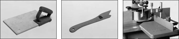
12 Jigs And Push Blocks
A pushblock is used to feed strips held down by the safety cutter guard. It should be made from 8-10 mm thick plywood.
A pushstick is used to feed stock which is held down only by the cutter guard's pressure shoe.
Mould across end grain only with the workpiece firmly supported in the sliding carriage. Very high risk of kickback and personal injury if no sliding carriage is used.
An auxiliary (or false) fence bridges the gap between the two fence plates to provide firm support and guiding for small workpieces. Retracting the fence, with the tool running, cuts through the auxiliary fence.
Strips shorter than 200 mm must be held in user-made feeding jigs for moulding.
13 Controls |
9 |
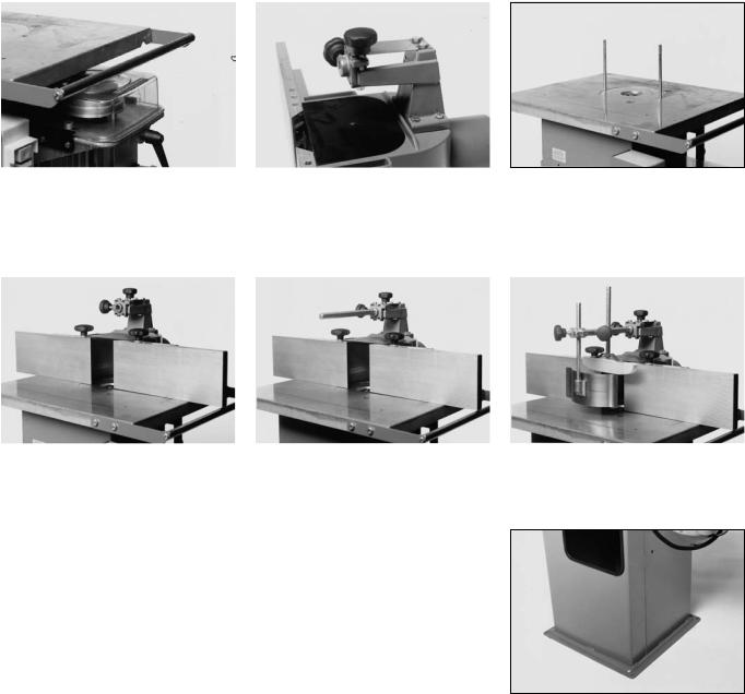
13.1 Definitions
8
3
7
6
2
5
1
4
1 |
Spindle |
6 |
Starting switch |
2 |
Spacing collars |
7 |
Table |
3 |
Spindle nut |
8 |
Fence plates |
4 |
Main frame |
9 |
Pressure shoe |
5 |
Handwheel for spindle vertical adjustment |
10 |
Fence |
|
|
11 |
Spindle lock |
10
11
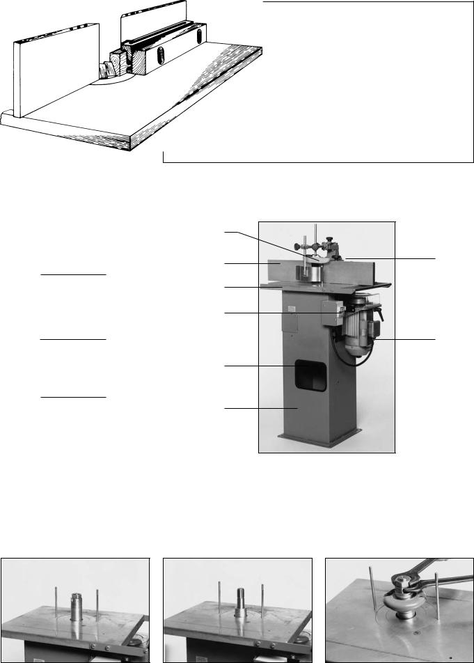
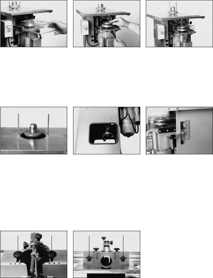
13.2 Mounting A Tool
For mounting or removing a tool it is recommended to remove the fence from the table.
The tool is held by the spacing collars. A rough height positioning on the spindle is done by placing spacing collars under the tool as required.
Place tool on spindle (mind direction of rotation) and spacing collars on top right up to the spindle thread. Then screw on the spindle nut.
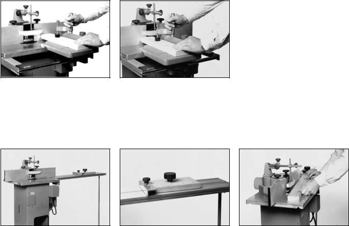
13.3 Spindle Speed Setting/Changing
Remove the plastic cover to have |
Loosen the ratchet lever and place |
access. |
belt on the desired step of the pulleys. |
|
Available speeds are: |
top |
= |
4000 min-1 |
centre |
= |
6000 min-1 |
lower |
= |
7500 min-1 |
Tighten the belt and replace the plastic guard.
13.4 Tool Height Setting
If the tool is only partially used and |
Spindle vertical adjustment is |
After a spindle height adjustment lock |
needs to be lowered below the table, |
achieved by turning the handwheel |
in position by engaging the spindle |
remove the table rings before moun- |
inside the main frame. Turn |
lock lever. |
ting it on the spindle. |
- clockwise to raise |
|
|
- counter-clockwise to lower |
|
Caution!
Switch machine off and let tool come to a complete stop before making any adjustments.
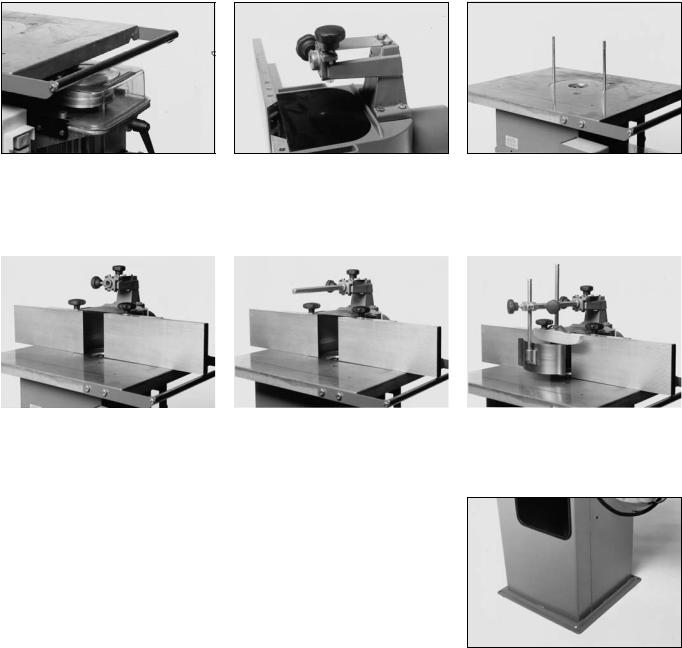
13.5 Fence And Fence Plate Setting
A |
A |
B |
B |
Caution!
Switch machine off and let tool come to a complete stop before making any adjustments.
Loosen both starknobs (A) to move the fence forward or backwards.
Loosen the starknobs (B) to reposition the fence plates.

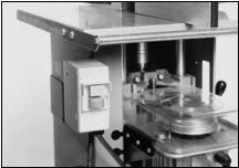
13.6 Cutter Guard Setting
D
E
C
Loosen starknob (C) and set holddown |
Adjust downward pressure with star- |
After loosening starknob (E) set spring |
shoe onto the workpiece. |
knob (D). |
guide against the workpiece. |
Caution!
Switch machine off and let tool come to a complete stop before making any adjustments.
14 Operation
14.1 Tools
This spindle moulder model TF 100 M must only be operated with tools having chip limitors for reduced kickback and approved for manual feed, e.g. BG-TEST tools or equivalent.
14.2Stock Prechecking
-Grown timber should be planed prior to any moulding operation.
-Do not work stock that is warped, bend or otherwise does not rest fully over its full length on the table and/or against the fence plates.
14.3Moulding Strips
-Mount tool as per section 13.2.
-Set/check spindle speed as per section 13.3.
-Adjust spindle and fence as per sections 13.4 and 13.5.
-Adjust cutter guard as per section 13.6 to accommodate the workpiece.
-Start machine and feed the workpiece with a steady motion slowly against the rotating tool.
Important!
Always use a pushblock to feed the work when near the end.
14.4 Moulding Boards
- Mount tool as per section 13.2. |
- |
Remove the cutter guard's pres- |
|
- |
Set/check spindle speed as per |
|
sure spring. |
|
section 13.3. |
- |
Set holddlown shoe as described |
- |
Adjust spindle and fence as per |
|
in section 13.6. |
|
sections 13.4 and 13.5. |
|
|
Caution!
Always feed with a pushstick if the workpiece width is less than 120 mm.
-Start machine and feed the workpiece with a steady motion slowly against the rotating tool.
14.5 Making Tenons
Tenons and grooves in end grain must only be made with the workpiece firmly held and guided by the sliding carriage TF 100, available as optional accessory.
To complete the tenon, turn workpiece over by 180° and make another pass.
Place workpiece on the sliding carriage's table and secure with the clamping arm. Lower the holddown shoe as much as possible to cover the space between the fence plates above the tool.
Start machine. Feed work slowly and with a steady motion against the rotating tool. When the pass is completed pull the sliding carriage back to its starting position.
14.5 Set-In Work
Install table extension according to Set the backstop as required. the instructions provided. Set tool,
fence and guard as required.
15 Care And Maintenance
Always disconnect from power before servicing.
Danger of severe personal injury if machine is started unintentionally.
-Lubricate all moving parts regularly with a few drops of motor oil.
-Clean table and fence plates regularly, keep resin-free.
Start machine. Place workpiece on the table and against the backstop, then push forward against the fence into the rotating tool.

U.K. Supplement to Operating Instructions for metabo
TF 100 M Spindle Moulder
Please note the following supplementary information associated with this machine:
U.K. Legislation and Codes of Practice
When used industrially within the U.K. this machine falls under the scope of:
-Woodworking Machines Regulations 1974
-Use and Provision of Work Equipment Regulations 1992
We strongly advise you study and follow these regulations.
Section 7.1 1-Phase Power Supply
230 V motor. Although the motors supplied with this machine will run safely on a 13A domestic ring main, on starting the machine a high current of very short duration is drawn, which could cause your 13A fuse to blow. If this persists we recommend to have the machine connected to a 16A separate radial circuit. Ensure a suitably sized fuse matching the motor is used.
This work should be undertaken only by a qualified electrician!
Wiring Instructions
Warning: This appliance must be earthed!
If the plug, fitted to the power cable supplied with the machine, has to be changed or replaced, connect the mains lead conductors in accordance with the following colour code.
Single-phase motors (110/115/220/230/240 volts):
Yellow/green |
- |
Earth |
Blue |
- |
Neutral |
Brown |
- |
Live |
Three-phase motors (220/380/400/415 volts):
Machines with a 3-phase motor are connected to power mains using a 5-pin industrial appliance-inlet/connector according to
VDE 0623/BS 4343/IEC 309.
4-wire mains lead |
Yellow/green |
- |
Earth |
|
Brown |
- |
Phase (L1) |
|
Black |
- |
Phase (L2) |
|
Blue |
- |
Phase (L3) |
5-wire mains lead |
Yellow/green |
- |
Earth |
|
Brown |
- |
Phase (L1) |
|
Black |
- |
Phase (L2) |
|
Black |
- |
Phase (L3) |
|
Blue |
- |
Neutral |
IF IN DOUBT - CONSULT A QUALIFIED ELECTRICIAN!
F
Table des matières
1 |
Caractéristiques techniques |
12 |
Accessoires d’amenée |
2 |
Responsabilité produit / Garantie |
13 |
Eléments de réglage |
3 |
Matériel livré |
13.1 |
Définition des termes |
4 |
Accessoires en option |
13.2 |
Montage de l’outil de fraisage |
5 |
Montage initial |
13.3 |
Réglage/modification de la vitesse |
6 |
Mise en place |
|
de rotation de broche |
7 |
Mise en service |
13.4 |
Réglage en hauteur de l’outil de fraisage |
7.1 |
Branchement sur réseau Ac-1 |
13.5 |
Ajustage du capot d’arrêt / des règles d’arrêt |
7.2 |
Branchement sur réseau Ac-3 |
13.6 |
Ajustage du dispositif presseur |
7.3 |
Sens de rotation |
14 |
Instructions de fonctionnement / Réglage |
7.4 |
Interrupteur |
14.1 |
Outils |
7.5 |
Protection contre les surcharges |
14.2 |
Conditions à remplir pour la matière brute |
7.6 |
Déclenchement à minimum de tension |
|
„bois massif“ |
7.7 |
Aspiration des copeaux |
14.3 |
Fraisage de lattes |
7.8 |
Mise en marche automatique du dispositif |
14.4 |
Fraisage de panneaux |
|
d’aspiration des copeaux |
14.5 |
Fraisage de tenons |
8 |
Consignes de sécurité |
14.6 |
Opérations de fraisage d’insertion |
9 |
Dimensions des pièces à travailler |
15 |
Entretien et maintenance |
10Emploi/Domaine d’application
11Dimensions des outils / Vitesse de coupe
1 Caractéristiques techniques |
TF 100 M/2,2 WN |
TF 100 M/2,8 DN |
Dimensions table |
523x423 mm |
523x423 mm |
Surface d'appui pièce |
150-210x600 mm |
150-210x600 mm |
Hauteur de travail |
850 mm |
850 mm |
Perçage de table Ø |
150 mm |
150 mm |
Anneaux de réduction |
2 |
2 |
Distance d'ajustement du capot d'arrêt |
30 mm |
30 mm |
Tubulure d'aspiration Ø |
100 mm |
100 mm |
Diamètre d'outil max. |
150 mm |
150 mm |
Epaisseur d'outil max. |
60 mm |
60 mm |
Diamètre broche |
30 mm |
30 mm |
Anneau de mandrin de fraisage Ø |
50 mm |
50 mm |
Elévation de la broche |
100 mm |
100 mm |
Vitesse de rotation broche |
4000/6000/7500 t/mn |
4000/6000/7500 t/mn |
Puissance moteur P1 |
2,2 kW S640% |
2,8 kW S640% |
Puissance moteur P2 |
1,1 kW S6-100% |
1,4 kW S6-100% |
Tension de service |
AC 1~230V/50 Hz |
AC 3~400 V/50 Hz |
Emission de bruit
Les niveaux sonores indiqués ci-dessous ont été déterminés suivant la méthode de mesure suivante: DIN 45 635, partie 1651.
Les niveaux de puissance sonore (LWA) sont arrondis et donnés en dB(A) entiers.
1. Fonctionnement de la TF 100 en marche à vide |
|
|
Niveau de pression sonore LpA |
77 dB(A) |
77 dB(A) |
(valeur émise au poste de travail) |
||
Niveau de puissance sonore LWA |
86 dB(A) |
86 dB(A) |
2. Fonctionnement de la TF en charge |
|
|
Niveau de pression sonore LpA |
82 dB(A) |
82 dB(A) |
(valeur émise au poste de travail) |
||
Niveau de puissance sonore LWA |
91 dB(A) |
91dB(A) |
2 Responsabilité produit / Garantie
Les travaux et possibilités d’emploi non mentionnés ici requièrent l’autorisation écrite de la société metabo.
12
Veuillez vous adresser à votre détaillant en cas de réclamations au titre de la garantie.
Les travaux de réparation au titre de la garantie sont par principe effectués par nous-mêmes ou par des points de service après-vente autorisés par nous.En dehors de la période de garantie, vous pouvez faire effectuer les réparations par toute société spécialisée adéquate.
Veuillez conserver les factures de réparation! Technische Änderungen vorbehalten!
3 Matériel livré:
Anneaux de mandrin de fraisage: 1 x 25 mm; 1 x 16 mm; 2 x 10 mm; 2 x 8 mm; 2 x 5 mm
Ecrou de mandrin de fraisage: M 30x2 Capot d’arrêt
4 |
Accessoires en option |
|
|
Rallonge de table |
Best.-Nr. 091 400 3598 |
|
Chariot coulissant |
Best.-Nr. 091 401 5600 |
|
Divers outils de fraisage |
Voir prospectus spécial |
Règles d’arrêt Dispositif presseur Outils de montage Notice d’instructions
5 Montage initial
Aligner le support d’appui avec la |
Fixer le chevalet support du dispositif |
|
Visser les deux goujons filetés dans |
|
table. |
presseur sur le capot d’arrêt. |
|
les trous taraudés du plateau de table. |
|
|
|
Boulonnerie: |
|
|
|
|
4 boulons à tête hexagonale M 6x25 |
|
|
|
|
4 écrous à freinage interne M6 |
|
|
|
|
|
|
|
|
|
|
|
|
Placer le capot d’arrêt sur la table |
Introduire les glissières parallèles |
Mettre en place la pièce de pression |
machine et le fixer. |
(barres hexagonales) et les bloquer. |
et le ressort de pression contre la |
|
|
glissière parallèle. |
6 Mise en place
Attention!
Pour assurer une meilleure stabilité statique, les fraiseuses de table TF 100 M doivent être vissées au sol. Utiliser des assemblages par vis adéquats, par ex. des chevilles à expansion de Ø 8 mm.
Les machines qui ne sont pas ancrées au sol peuvent se renverser en cours de fonctionnement - Danger d’accident.
7 Mise en service
7.1 Branchement sur réseau Ac-1
Modèle pour courant alternatif
Le branchement sur le réseau est fait au moyen d’une fiche à contact de protection conformément à la norme VDE 0100. La prise sur laquelle la machine est branchée doit être mise à la terre de façon réglementaire et munie d’un disjoncteur à courant de défaut de 30 mA. La tension de réseau doit être de 230 V/50 Hz. La protection par fusible doit être faite par fusible de 16 A (à action retardée). La section du conducteur doit avoir au moins 3x2,5 mm2.
7.2 Branchement sur réseau Ac-3
Modèle pour courant triphasé
Le branchement sur le réseau est fait au moyen d’une fiche CEE de 16 A. La prise de courant sur laquelle la machine est branchée doit être pourvue d’un câble d’amenée à 5 conducteurs - L1 - L2 - L3 - N - PE et munie d’un disjoncteur à courant de défaut de 30 mA. La tension de réseau doit être de 3~400 V/50 Hz ± 5%. La protection par fusibles doit être faite par fusibles de 3x16 A (à action retardée). La section du conducteur doit avoir au moins 5x1,5 mm2.
7.3 Sens de rotation
Pour les machines à moteur monophasé (230 V, courant alternatif), le sens de rotation est prédéfini en usine. Pour les machines à moteur triphasé (400V courant triphasé), il faut vérifier le sens de rotation par une brève mise en route de la machine. Vue du dessus, la broche de fraisage doit tourner vers la gauche. Pour modifier le sens de rotation, il faut permuter deux des conducteurs sous tension (noir et/ou marron). Ne pas permuter le conducteur de protection jaune-vert avec un conducteur sous tension.
Attention!
Si la machine tourne dans le mauvais sens, il y a risque d’accident! Vérifier donc avec soin le sens de rotation. La modification du sens de rotation ne peut être effectuée que par un électricien professionnel!
7.4 Interrupteur
Actionner le bouton-poussoir vert pour mettre en marche la machine et le bouton-poussoir rouge pour l’arrêter.
7.5 Protection contre les surcharges
S’il y a surcharge du moteur, le disjoncteur-protecteur intégré arrête la machine. Le moteur échauffé par la surcharge doit seulement être redémarré après une période d’arrêt d’environ 10 minutes.
7.6 Déclenchement à minimum de tension
Tant que la machine n’est pas branchée sur le réseau, le commutateur ne peut pas être actionné. En cas de panne de secteur, l’interrupteur est ouvert automatiquement grâce à un relais à minimum de tension intégré, c’est-à-dire que la machine doit être remise en marche après rétablissement de l’alimentation en courant.
7.7 Aspiration des copeaux
La fraiseuse de table doit être équipée d’un dispositif d’aspiration des copeaux. - La poussière de bois de hêtre ou de chêne est cancérigène.
Le dispositif d’aspiration des copeaux auquel est raccordée la machine doit atteindre une vitesse d’air d’au moins 16 m/sec à la tubulure d’aspiration. La tubulure d’aspiration a une section nominale de Ø 100 mm.
7.8 Mise en marche automatique du dispositif d’aspiration des copeaux
Le branchement électrique de la machine doit être tel que le dispositif d’aspiration des copeaux se mette en route automatiquement au démarrage de la machine et continue à fonctionner 20 secondes après l’arrêt de la machine.

8Consignes de sécurité
-Observer les instructions de service.
-Faire fonctionner la machine uniquement avec des outils ayant subi les tests BG.
-La vitesse de rotation maximale des outils ne doit pas être dépassée.
-Suivre les instructions de service respectives des outils employés.
-Les dimensions d’outils maximales ne doivent pas être dépassées.
-Les dimensions maximales et minimales des pièces à travailler doivent être respectées.
-Débrancher la prise au secteur avant d’effectuer tous travaux d’entretien et de maintenance.
-Attendre toujours l’arrêt complet de la machine avant de supprimer des dérangements.
-Le dispositif presseur et le capot d’arrêt doivent être ajustés convenablement suivant la tâche à effectuer.
-Toujours pousser les lattes et autres pièces à travailler similaires avec une pièce de bois coulissante / un bâton à pousser.
-Respecter les vitesses de coupe (para. 11.0).
-Il est interdit aux jeunes gens de moins de 16 ans de faire fonctionner cette machine.
9Dimensions des pièces à travailler
-Amener les pièces d’une longueur inférieure à 200 mm contre l’outil uniquement au moyen d’un dispositif d’amenée adéquat.
-Les pièces d’une longueur supérieure à 1000 mm doivent être maintenues au moyen d’une rallonge de table (accessoire en option) ou de chevalets à rouleaux pour éviter qu’elles ne basculent et tombent de la table machine.
-Les pièces à travailler (panneaux) peuvent avoir une largeur maximale de 500 mm.
10Emploi/Domaine d'application
-Les fraiseuses de table TF 100 conviennent au travail du bois massif et/ou de matériaux similaires, tels que panneaux d’agglomérés, panneaux de fibres ou contreplaqué.
-Le fraisage en bout, comme par ex. la coupe de tenons ne doit pas être effectué sans le chariot coulissant livré comme accessoire en option.
-Les travaux de fraisage d’insertion ne doivent pas être réalisés sans la rallonge de table livrée comme accessoire en option.
-On ne doit pas exécuter de fraisage en cintre (travaux avec anneau de butée) avec cette machine.
-On ne doit pas exécuter de fraisage en sens direct (fraisage à pièce suivante) avec cette machine.
11Dimensions des outils / Vitesse de coupe
La vitesse de coupe de l’outil de fraisage utilisé doit toujours être supérieure à 35 m/sec pour diminuer le risque de choc en retour.
-A la vitesse de rotation de broche de 4000 t/min, on ne doit employer la machine avec aucun outil de fraisage. Cette vitesse de rotation de broche est prévue pour des brosses, des lames de scie et autres accessoires similaires.
-A la vitesse de rotation de broche de 6000 t/min, l’outil doit présenter un diamètre d’au moins 115 mm (rayon de coupe de lame).
-A la vitesse de rotation de broche de 7500 t/min, l’outil doit présenter un diamètre d’au moins 90 mm (rayon de coupe de lame).
-Aux deux vitesses de rotation convenables pour le fraisage (6000 et 7500 t/min), on peut utiliser le diamètre d’outil maximal admis de 150 mm.
-L’épaisseur d’outil maximale est de 60 mm.
12 Accessoires d'amenée
La pièce de bois coulissante sert à pousser des lattes maintenues avec le dispositif presseur. La pièce de bois coulissante doit avoir environ 8-10 mm d’épaisseur et être faite en contreplaqué.
Le bâton à pousser sert à pousser des pièces qui sont seulement maintenues avec le bâton de pression du dispositif presseur.
Le fraisage en bout (tenons) ne doit pas être fait sans le chariot coulissant livré comme accessoire en option.
 Loading...