


RS 4000
 Betriebsanleitung . . . . . . . . . . . . . . . . . . . . 3
 Operating Instructions . . . . . . . . . . . . . . . . 6
 Instructions d'utilisation . . . . . . . . . . . . . . . 9
Handleiding . . . . . . . . . . . . . . . . . . . . . . . 12
 Betjeningsvejledning . . . . . . . . . . . . . . . . 15
Bruksanvisning . . . . . . . . . . . . . . . . . . . . 18
Instrukcja obsługi. . . . . . . . . . . . . . . . . . . 21
 Návod k obsluze . . . . . . . . . . . . . . . . . . . 25
Käyttökäsikirja . . . . . . . . . . . . . . . . . . . . . 28
 Bruksanvisning . . . . . . . . . . . . . . . . . . . . 31
 Руководство по эксплуатации. . . . . . . . 34
115 171 6993 / 0305 - 1.0

D
KONFORMITÄTSERKLÄRUNG
Wir erklären in alleiniger Verantwortlichkeit, dass dieses Produkt mit den folgenden Normen übereinstimmt* gemäß den Bestimmungen der Richtlinien**
F
DECLARATION DE CONFORMITE
Nous déclarons, sous notre seule responsabilité, que ce produit est en conformité avec les normes ou documents normatifs suivants* en vertu des dispositions des directives **
IT
DICHIARAZIONE DI CONFORMITÀ
Noi dichiariamo sotto la nostra esclusiva responsabilità che il presente prodotto è conforme alle seguenti norme* in conformità con le disposizioni delle normative **
PT
DECLARAÇÃO DE CONFORMIDADE
Declaramos sob nossa responsabilidade que este produto está de acordo com as seguintes normas* de acordo com as directrizes dos regulamentos **
FIN
VAATIMUKSENMUKAISUUSVAKUUTUS
Vakuutamme, että tämä tuote vastaa seuraavia normeja* on direktiivien määräysten mukainen**
DA
OVERENSSTEMMELSESATTEST
Hermed erklærer vi på eget ansvar, at dette produkt stemmer overens ed følgende standarder* iht bestemmelserne i direktiverne**
EL
∆ΗΛΩΣΗ ΑΝΤΙΣΤΟΙΧΕΙΑΣ ∆ηλώνουµε µε ιδία ευθύνη ότι το προϊόν αυτό αντιστοιχεί στις ακόλουθες
προδιαγραφές* σύµφωνα µε τις διατάξεις των οδηγιών**
CZ
Souhlasné prohlášení
Tímto na vlastní zodpovědnost prohlašujeme, že tento výrobek splňuje níže uvedené normy* normativní nařízení** směrnice EU*** zprávu technické kontroly****
BG
ДЕКЛАРАЦИЯ ЗА СЪОТВЕТСТВИЕ
С ПЪЛНА ОТГОВОРНОСТ ДЕКЛАРИРАМЕ, ЧЕ ТОЗИ ПРОДУКТ СЪОТВЕТСТВА НА СЛЕДНИТЕ НОРМАТИВНИ ДОКУМЕНТИ* СЪГЛАСНО ИЗИСКВАНИЯТА НА ДИРЕКТИВИТЕ**
ENG
DECLARATION OF CONFORMITY
We herewith declare in our sole repsonsibility that this product complies with the following standards* in accordance with the regulations of the undermentioned directives**
NL
CONFORMITEITSVERKLARING
Wij verklaren als enige verantwoordelijke, dat dit product in overeenstemming is met de volgende normen*
conform de bepalingen van de richtlijnen**
ES
DECLARACION DE CONFORMIDAD
Declaramos bajo nuestra exclusiva responsabilidad, que el presente producto cumple con las siguientes normas* de acuerdo a lo dispuesto en las directrices**
SV
FÖRSÄKRAN OM ÖVERENSSTÄMMELSE
Vi försäkrar på eget ansvar att denna produkt överensstämmer med följande standarder* enligt bestämmelserna i direktiven**
NO
SAMSVARSERKLÆRING
Vi erklærer under eget ansvar at dette produkt samsvarer med følgende normer* henhold til bestemmelsene i direktiv**
POL
OŚWIADCZENIE O ZGODNOŚCI
Oświadczamy z pełną odpowiedzialnością, że niniejszy produkt odpowiada wymogom następujących norm* według ustaleń wytycznych **
HU
MEGEGYEZŐSÉGI NYILATKOZAT
Kizárólagos felelősségünk tudatában ezennel igazoljuk, hogy ez a termék kielégíti az alábbi szabványokban lefektetett követelményeket* megfelel az alábbi irányelvek előírásainak**
RO
DECLARATIE DE CONFORMITATE
Declaram pe proprie raspundere ca acest produs corespunde urmatoarelor norme* conform prevederilor liniilor directoare** verificare UE pentru mostre*** efectuata de****
SK
Konformné prehlásenie
Prehlasujeme s plnou zodpovednostou, ze tento výrobok je v zhode s nasledovnými normami* podla ustanovení smerníc **
RATSCHENSCHRAUBER
1/2" RS 4000
EN 292-1: Section 5(1992), EN 292-2 Section 3(1992), EN 1050, EN 729-1, EN ISO 15744(2002), ISO 8662-7(1997)
** 98/37/EG
Ing. grad. Hans-Joachim Schaller
Leitung Entwicklung und Konstruktion
Metabowerke GmbH
Business Unit Elektra Beckum
Daimlerstr. 1
D - 49716 Meppen
Meppen, 14.01.2005 |
1001157 |
2

DEUTSCH 
1. Das Gerät im Überblick
1 |
2 |
3 |
6 |
5 |
4 |
1Umschaltknopf für Rechts-/ Linkslauf
2Handgriff
3Aufnahme für Stecknippel (Druckluft-Anschluss)
4Abzughebel
5Luftaustritt, schallgedämpft
6Vierkantaufnahme (1/2 ") für Stecknüsse
Ohne Abbildung:
Stecknippel 1/4 " (Deutschland)
Stecknippel 1/4 "
(Frankreich, Spanien)
Stecknippel 1/4 " (Schweiz, Belgien, Niederlande)
Ölfläschchen
3

|
DEUTSCH |
|
Inhaltsverzeichnis |
|
|
1. |
Das Gerät im Überblick |
...............3 |
2. |
Zuerst lesen!................................ |
4 |
3. |
Sicherheit..................................... |
4 |
3.1 |
Bestimmungsgemäße |
|
|
Verwendung .................................. |
4 |
3.2 |
Allgemeine |
|
|
Sicherheitshinweise ...................... |
4 |
3.3 |
Symbole auf dem Gerät ................ |
4 |
4. |
Betrieb.......................................... |
5 |
4.1 |
Vor dem ersten Betrieb ................. |
5 |
4.2 |
Werkzeug benutzen ...................... |
5 |
5. |
Wartung und Pflege .................... |
5 |
6. |
Lieferbares Zubehör ................... |
5 |
7. |
Reparatur ..................................... |
5 |
8. |
Umweltschutz .............................. |
5 |
9. |
Technische Daten ....................... |
5 |
2. Zuerst lesen!
Diese Betriebsanleitung wurde so erstellt, dass Sie schnell und sicher mit Ihrem Werkzeug arbeiten können. Hier ein kleiner Wegweiser, wie Sie diese Betriebsanleitung lesen sollten:
•Lesen Sie diese Betriebsanleitung vor der Inbetriebnahme ganz durch. Beachten Sie insbesondere die Sicherheitshinweise.
•Wenn Sie beim Auspacken einen Transportschaden feststellen, benachrichtigen Sie umgehend Ihren Händler. Nehmen Sie das Werkzeug nicht in Betrieb!
•Diese Betriebsanleitung richtet sich an Personen mit technischen Grundkenntnissen im Umgang mit Werkzeugen wie dem hier beschriebenen. Wenn Sie keinerlei Erfahrung mit solchen Werkzeugen haben, sollten Sie zunächst die Hilfe von erfahrenen Personen in Anspruch nehmen.
•Bewahren Sie alle mit diesem Werkzeug gelieferten Unterlagen auf, damit Sie sich bei Bedarf informieren können. Bewahren Sie den Kaufbeleg für eventuelle Garantiefälle auf.
•Wenn Sie das Werkzeug einmal verleihen oder verkaufen, geben Sie alle mitgelieferten Unterlagen mit.
Für Schäden, die entstehen, weil diese Betriebsanleitung nicht beachtet wurde, übernimmt der Hersteller keine Haftung.
Die Informationen in dieser Betriebsanleitung sind wie folgt gekennzeichnet:
Gefahr!
Warnung vor Personenschäden oder Umweltschäden.
Achtung!
Warnung vor Sachschäden.
−Zahlen in Abbildungen (1, 2, 3, ...)
−kennzeichnen Einzelteile;
−sind fortlaufend durchnummeriert.
−Handlungsanweisungen, bei denen die Reihenfolge beachtet werden muss, sind durchnummeriert.
−Handlungsanweisungen mit beliebiger Reihenfolge sind mit einem Punkt gekennzeichnet.
−Auflistungen sind mit einem Strich gekennzeichnet.
3. Sicherheit
3.1Bestimmungsgemäße Verwendung
Dieses Werkzeug dient zum Befestigen und Lösen von Sechskantschrauben und Sechskantmuttern.
Mit dem Ratschenschrauber dürfen Schrauben nur bis zum Erreichen des maximalen Drehmoments angezogen werden.
Dieses Werkzeug darf nur durch einen Druckluftkompressor angetrieben werden. Der in den Technischen Daten angegebene maximal zulässige Arbeitsdruck darf nicht überschritten werden. Dieses Werkzeug darf nicht mit explosiven, brennbaren oder gesundheitsgefährdenden Gasen betrieben werden.
Jede andere Verwendung ist bestimmungswidrig. Durch bestimmungswidrige Verwendung, Veränderungen am Werkzeug oder durch den Gebrauch von Teilen, die nicht vom Hersteller geprüft und freigegeben sind, können unvorhersehbare Schäden entstehen!
3.2Allgemeine Sicherheitshinweise
•Beachten Sie beim Gebrauch dieses Werkzeugs die folgenden Sicherheitshinweise, um Gefahren für Personen oder Sachschäden auszuschließen.
•Beachten Sie die speziellen Sicherheitshinweise in den jeweiligen Kapiteln.
•Beachten Sie gegebenenfalls spezielle Arbeitsschutzoder Unfallverhü- tungs-Vorschriften für den Umgang mit Kompressoren und DruckluftWerkzeugen.
AAllgemeine Gefahren!
•Halten Sie Ihren Arbeitsbereich in Ordnung – Unordnung im Arbeitsbereich kann Unfälle zur Folge haben.
•Seien Sie aufmerksam. Benutzen Sie dieses Werkzeug nicht, wenn Sie unkonzentriert sind.
•Vermeiden Sie ein Verkanten des Werkzeugs – sorgen Sie für einen sicheren Stand, wenn Sie das Werkzeug benutzen.
•Schließen Sie dieses Werkzeug nur über eine Schnellkupplung an einen Kompressor an.
•Stellen Sie sicher, dass der in den Technischen Daten angegebene maximal zulässige Arbeitsdruck nicht überschritten wird.
•Überlasten Sie dieses Werkzeug nicht – benutzen Sie dieses Werkzeug nur im Leistungsbereich, der in den Technischen Daten angegeben ist.
•Berühren Sie keine rotierenden Teile.
•Trennen Sie dieses Werkzeug vom Druckluftanschluss, bevor Sie Stecknüsse wechseln oder wenn das Werkzeug unbeaufsichtigt ist.
AGefahr durch unzureichende persönliche Schutzausrüstung!
•Tragen Sie einen Gehörschutz.
•Tragen Sie eine Schutzbrille.
AGefahr durch Mängel am
Gerät!
•Reparieren Sie dieses Werkzeug nicht selbst! Nur Fachleute dürfen Reparaturen an Kompressoren, Druckbehältern und Druckluft-Werk- zeugen durchführen.
A Achtung!
Schützen Sie das Gerät, insbesondere den Druckluftanschluss, die Vierkantaufnahme und die Bedienelemente vor Staub und Schmutz.
3.3Symbole auf dem Gerät
Gefahr!
Missachtung der folgenden Warnungen kann zu schweren Verletzungen oder Sachschäden führen.
Betriebsanleitung lesen.
Gehörschutz tragen.
4

Schutzbrille tragen.
4. Betrieb
4.1Vor dem ersten Betrieb
•Stecknippel einschrauben.
4.2Werkzeug benutzen
A Achtung!
Damit dieses Werkzeug lange einsatzbereit bleibt, muss es ausreichend mit Pneumatiköl versorgt werden. Dies kann wie folgt geschehen:
−Über eine Wartungseinheit mit Öler am Kompressor.
−Über einen Leitungsöler, der direkt am Druckluftwerkzeug oder an der Druckluftleitung installiert ist.
−Pro 15 Betriebsminuten (Dauereinsatz) etwa 3 bis 5 Tropfen Pneumatiköl von Hand in den Druckluftanschluss geben.
1.Stecknuss auf die Vierkantaufnahme stecken.
2.Drehrichtung am Umschaltknopf für Rechts-/Linkslauf einstellen:
−Umschaltknopf nach links: F = Rechtslauf/Festdrehen
−Umschaltknopf nach rechts: R = Linkslauf/Losdrehen
3.Arbeitsdruck am Kompressor einstellen (maximal zulässiger Arbeitsdruck siehe Technische Daten).
4.Schnellkupplung an die Druckluftversorgung anschließen.
5.Zum Einschalten, Abzughebel betätigen.
5.Wartung und Pflege
AGefahr!
Vor allen Arbeiten am Werkzeug Druckluftanschluss trennen. Weitergehende Wartungsoder Reparaturarbeiten, als die in diesem Kapitel beschriebenen, dürfen nur Fachkräfte durchführen.
•Verschraubungen auf festen Sitz prüfen, ggf. festziehen.
•Wenn das Werkzeug nicht durch eine Wartungseinheit oder einen Leitungsöler geölt wird, pro 15 Betriebsminuten (Dauereinsatz) etwa 3 bis 5 Tropfen Pneumatiköl von Hand in den Druckluftanschluss geben.
•Werkzeug nicht ungeschützt im Freien oder in feuchter Umgebung aufbewahren.
6. Lieferbares Zubehör
•Pneumatiköl 0,5 Liter
Spezialöl für Druckluftwerkzeuge, Wartungseinheiten und Leitungsöler.
Art.-Nr. 090 100 8540
•Leitungsöler R1/4" Innengewinde Zur Installation direkt an Druckluftwerkzeugen. Stets sichtbarer Ölstand durch Schauglas.
Art.-Nr. 090 105 4584
DEUTSCH 
•Dreh-Kipp-Lufteinlassgelenk DKG 1/4"
Zur Installation direkt an Druckluftwerkzeugen. Verbesserte Beweglichkeit beim Werkzeugeinsatz.
Art.-Nr. 090 106 0991
•Nussensatz 1/2" Bestehend aus 10 Nussen
(10, 11,12, 13, 15, 17, 19, 21, 22, 24 mm).
7. Reparatur
AGefahr!
Reparaturen an Druckluftwerkzeugen dürfen nur durch eine Fachkraft ausgeführt werden!
Reparaturbedürftige Druckluftwerkzeuge können an die Service-Niederlassung Ihres Landes eingesandt werden. Die Adresse finden Sie bei der Ersatzteilliste.
Bitte beschreiben Sie bei der Einsendung zur Reparatur den festgestellten Fehler.
8. Umweltschutz
Das Verpackungsmaterial der Maschine ist zu 100 % recyclingfähig.
Ausgediente Maschinen und Zubehör enthalten große Mengen wertvoller Rohund Kunststoffe, die ebenfalls einem Recyclingprozess zugeführt werden können.
Die Anleitung wurde auf chlorfrei gebleichtem Papier gedruckt.
9. Technische Daten
Modell |
|
RS 4000 |
|
|
|
Luftbedarf |
l/min |
490 |
|
|
|
Maximal zulässiger Arbeitsdruck |
bar |
6,2 |
|
|
|
Drehzahl |
min-1 |
160 |
|
|
|
Vierkantaufnahme |
" |
1/2 |
|
|
|
Maximale Schraubengröße |
|
M13 |
|
|
|
Maximales Drehmoment (Rechtslauf) |
Nm |
95 |
|
|
|
Maximales Drehmoment (Linkslauf) |
Nm |
95 |
|
|
|
Minimaler Schlauchdurchmesser (innen) |
mm |
13 |
|
|
|
Vibration (gewichteter Effektivwert der Beschleunigung) |
m/s2 |
1,13 |
|
|
|
Schallleistungspegel LWA |
dB (A) |
92,9 |
Schalldruckpegel LPA |
dB (A) |
103,9 |
Abmessungen: |
|
|
Länge x Breite x Höhe |
mm |
305 x 46 x 48 |
|
|
|
Gewicht |
kg |
1,2 |
|
|
|
5

 ENGLISH
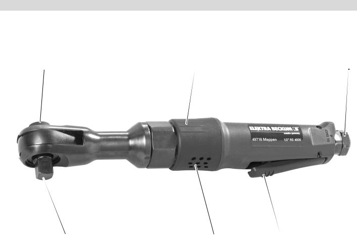
1. Components and Parts
1 |
2 |
3 |
6 |
5 |
4 |
1Reversing knob for forward/ reverse rotation
2Handle
3Plug seat on air inlet
4Trigger
5Exhaust port with muffler
6Square drive spindle (1/2 ") for sockets
Not shown:
Plug 1/4 " (Germany)
Plug 1/4 "
(France, Spain)
Plug 1/4 "
(Switzerland, Belgium, Holland)
Oil flask
6
Table of Contents |
|
|
1. |
Components and Parts .............. |
6 |
2. |
Please Read First!....................... |
7 |
3. |
Safety ........................................... |
7 |
3.1 |
Specified Conditions of Use.......... |
7 |
3.2 |
General Safety Instructions .......... |
7 |
3.3 |
Symbols Used............................... |
7 |
4. |
Operation..................................... |
7 |
4.1 |
Before Initial Operation ................. |
7 |
4.2 |
Using the Tool............................... |
7 |
5. |
Care and Maintenance................ |
8 |
6. |
Available Accessories................ |
8 |
7. |
Repairs......................................... |
8 |
8. |
Environmental Protection .......... |
8 |
9. |
Technical Specifications............ |
8 |
2. Please Read First!
These instructions are written in a way to let you work with the tool quickly and safely. Here is how to use the instructions:
•Read these instructions fully before operating the tool. Pay special attention to the safety information.
•If you notice transport damage while unpacking, notify your supplier immediately. Do not operate the tool!
•These operating instructions are intended for people with basic technical knowledge regarding the operation of a tool like this or similar air tools. Inexperienced persons are strongly advised to seek competent advise and guidance from an experienced person before operating this tool.
•Keep all documents supplied with this tool for future reference. Also, retain proof of purchase in case of a warranty claim.
•This tool must not be sold or lent to someone else without being accompanied by these operating instructions and all other documents supplied with the tool.
The manufacturer is not liable for any damage caused by the non-observance of these operating instructions.
Information in these instructions is denoted as under:
Danger!
Risk of personal injury or environmental damage.
Caution!
Risk of material damage.
−At times numbers are used in illustrations (1, 2, 3, ...). These numbers:
−indicate component parts;
−are consecutively numbered;
−Numbered steps must be carried out in sequence.
−Instructions which can be carried out in any order are indicated by a bullet point (•).
−Listings are indicated by a dash (–).
3. Safety
3.1Specified Conditions of Use
This tool is used for running, driving and removing nuts and bolts.
With this ratchet wrench bolts may only be tightened up to the air tool's maximum torque.
This tool shall only be powered by an air compressor. The max. permissible working pressure stated in the Technical Specifications must not be exceeded. This tool must not be operated with gases that are explosive, combustible or detrimental to health.
Any other use is not as specified. Use not as specified, modification of the tool or use of parts not approved by the manufacturer can cause unforeseeable damage!
3.2General Safety Instructions
•When using this air tool observe the following safety instructions to minimize the risk of personal injury or material damage.
•Please also observe the special safety instructions in the respective chapters.
•Observe the statuary accident insurance institution regulations and regulations for the prevention of accidents pertaining to the operation of air compressors and air tools, where applicable.
AGeneral danger!
•Keep your work area tidy – a messy work area invites accidents.
•Be alert. Do not operate this tool while under the influence of drugs, alcohol or medication.
•Keep the tool from jamming – ensure firm footing when using the tool.
•Always use a quick coupler to connect this air tool to a compressor.
•Make sure that the max. permissible working pressure stated in the Technical Specifications is not exceeded.
ENGLISH
•Do not overload tool – use it only within the performance range it was designed for (see Technical Specifications).
•Do not touch any rotating parts.
•Disconnect tool from air supply before changing sockets or if left unattended.
AHazard generated by insufficient personal protection gear!
•Wear hearing protection.
•Wear safety glasses.
AHazard generated by tool defects!
•Do not attempt to repair the tool yourself! Only trained specialists are permitted to service or repair compressors, pressure vessels and air tools.
A Caution!
Protect the tool, air inlet, square drive and operating elements in particular, from dust and dirt.
3.3Symbols Used
Danger!
Neglect of the following warnings may cause serious injury or material damage.
Read instructions.
Wear hearing protection.
Wear safety goggles.
4. Operation
4.1Before Initial Operation
•Install the plug nipple.
4.2Using the Tool
A Caution!
To ensure a long service life of this tool, it needs to be supplied with sufficient quantities of pneumatic oil. This can be achieved by:
−a service unit with oiler at the compressor.
−a lubricator, installed directly on the air tool or in the air line.
7

 ENGLISH
−adding approx. 3-5 drops of pneumatic oil by hand every 15 minutes of operation (continuous operation) to the air inlet.
1.Put socket on the drive.
2.Set direction of rotation with the reversing knob:
−reversing knob set to the left: forward/driving
−Reversing knob set to the right: R = reverse/loosening
3.Adjust working pressure at the compressor (see Technical Specifications for max. permissible working pressure).
4.Connect quick coupler to the air supply.
5.Pull trigger to start.
5. Care and Maintenance
ADanger!
Always disconnect from air supply before servicing.
Repair and maintenance work other than described in this section must
be carried out by qualified specialists only .
•Check all screwed connections for tightness, tighten if necessary.
•When the tool is not lubricated by a service unit or line oiler, manually add 3 - 5 drops of pneumatic oil for every 15 minutes of operation (continuous operation) into the air inlet.
•Never store the tool outdoors, in unprotected areas or in damp locations.
6. Available Accessories
•Pneumatic oil 0.5 litre
Special lubricant for air tools, service units and line oilers.
Stock-no. 090 100 8540
•Line oiler R1/4" female
For fitting directly to air tools. Oil level can always be checked through sight glass.
Stock-no. 090 105 4584
•Swivel-type air inlet DKG 1/4"
For fitting directly to air tools. Improves tool manoeuverability. Stock-no. 090 106 0991
•Socket set 1/2" consisting of 10 sockets
(10, 11, 12, 13, 15, 17, 19, 21, 22, 24 mm).
7. Repairs
ADanger!
Repairs to air tools must be carried out by qualified specialists ONLY!
Air tools in need of repair can be send to the service centre in your country. See Spare Parts List for address.
Please attach a description of the fault to the air tool.
8. Environmental Protection
The tool's packaging materials are 100 % recyclable.
Worn out machines and accessories contain considerable amounts of valuable raw and plastic materials, which can be recycled.
These instructions are printed on paper produced with elemental chlorine free bleaching process.
9. Technical Specifications
Model |
|
RS 4000 |
|
|
|
Air consumption |
l/min |
490 |
|
|
|
Max. permissible working pressure |
bar |
6.2 |
|
|
|
Speed |
min-1 |
160 |
Square drive |
" |
1/2 |
|
|
|
Maximum bolt size |
|
M13 |
|
|
|
Maximum torque (forward) |
Nm |
95 |
|
|
|
Maximum torque (reverse) |
Nm |
95 |
|
|
|
Minimum hose size (inner) |
mm |
13 |
|
|
|
Vibration (effective value of weighted acceleration) |
m/s2 |
1.13 |
Sound power level LWA |
dB (A) |
92.9 |
Sound pressure level LPA |
dB (A) |
103.9 |
Dimensions: |
|
|
length x width x height |
mm |
305 x 46 x 48 |
|
|
|
Weight |
kg |
1.2 |
|
|
|
8
FRANÇAIS 
1. Vue d'ensemble de l'appareil
1 |
2 |
3 |
6 |
5 |
4 |
1Bouton d'inversion droite/gauche
2Poignée
3Logement pour embout (raccord air comprimé)
4Gâchette
5Sortie d'air insonorisée
6Embout carré (1/2 ") pour douilles
Sans illustration :
Embout 1/4 " (Allemagne)
Embout 1/4 "
(France, Espagne)
Embout 1/4 "
(Suisse, Belgique, Pays-Bas)
Burette d'huile
9
|
FRANÇAIS |
|
Table des matières |
|
|
1. |
Vue d'ensemble de l'appareil |
.....9 |
2. |
À lire en premier !...................... |
10 |
3. |
Sécurité ...................................... |
10 |
3.1 |
Utilisation conforme aux |
|
|
prescriptions................................ |
10 |
3.2 |
Consignes de sécurité |
|
|
générales .................................... |
10 |
3.3 |
Symboles sur l'appareil ............... |
10 |
4. |
Fonctionnement ........................ |
11 |
4.1 |
Avant la première mise en |
|
|
service......................................... |
11 |
4.2 |
Utilisation de l'outil....................... |
11 |
5. |
Maintenance et entretien .......... |
11 |
6. |
Accessoires disponibles .......... |
11 |
7. |
Réparations ............................... |
11 |
8. |
Protection de |
|
|
l'environnement......................... |
11 |
9. |
Caractéristiques techniques .... |
11 |
2. À lire en premier !
Ces instructions ont été conçues de façon à permettre à l'utilisateur de travailler rapidement et sûrement avec son outil. Les remarques qui suivent vous aideront à utiliser ces instructions :
•Lire entièrement ces instructions avant de mettre en marche l'outil. Respecter en particulier les consignes de sécurité.
•Si des dommages dus au transport sont constatés pendant le déballage, en informer aussitôt le revendeur. Ne pas mettre l'outil en marche !
•Ces instructions d'utilisation s'adressent à des personnes possédant des connaissances techniques de base concernant le maniement d'outils tels que celui décrit ici. Nous recommandons aux personnes ne disposant pas de ces bases de se faire assister par des personnes plus expérimentées.
•Conserver toute la documentation fournie avec l'appareil afin de pouvoir la consulter ultérieurement en cas de besoin. Conserver le justificatif de paiement pour éventuellement faire appel à la garantie.
•En cas de vente ou de location de l'appareil, fournir également ces instructions.
Le fabricant décline toute responsabilité en cas de dommages dus au non-res- pect de ces instructions.
Les informations qui figurent dans ces instructions sont caractérisées comme suit :
Danger !
Avertissement d'un risque de blessure ou de pollution.
Attention ! Avertissement d'un risque de dommage matériel.
−Les numéros des illustrations (1, 2, 3, ...)
−caractérisent les différentes pièces ;
−sont attribués en ordre croissant.
−Les manipulations à effectuer dans un ordre précis sont numérotées.
−Les manipulations à effectuer sans ordre précis sont précédées d'un point.
−Les listes sont caractérisées par des tirets.
3. Sécurité
3.1Utilisation conforme aux prescriptions
Cet appareil sert à fixer et à desserrer des vis et des écrous à six pans.
Ne pas dépasser le couple maximal en serrant des vis avec la visseuse à cliquet.
Cet appareil ne doit être entraîné que par un compresseur à air comprimé. La pression de travail maximale indiquée dans les caractéristiques techniques ne doit pas être dépassée. Ne pas faire fonctionner cet appareil avec des gaz explosibles, combustibles ou présentant un danger pour la santé.
Toute autre utilisation est contraire aux prescriptions. Une utilisation non conforme aux prescriptions, des modifications apportées à l'appareil ou l'emploi de pièces qui n'ont pas été contrôlées ni approuvées par le fabricant peuvent entraîner des dommages imprévisibles !
3.2Consignes de sécurité générales
•Tenir compte des consignes de sécurité suivantes afin d'exclure les risques de blessures ou de dommages matériels.
•Respecter les consignes de sécurité particulières dans les différents chapitres.
•Tenir compte le cas échéant des prescriptions relatives à la sécurité du travail ou à la prévention des accidents concernant le maniement des compresseurs et des outils à air comprimé.
APrincipaux dangers !
•Maintenir le lieu de travail en ordre – un désordre sur le lieu de travail peut entraîner des accidents.
•Il convient de rester vigilant. N'utilisez pas cet outil si vous n'êtes pas concentré.
•Éviter de coincer l'outil – assurer une bonne stabilité pour utiliser l'appareil.
•Cet outil ne doit être raccordé à un compresseur que par un accouplement rapide.
•S'assurer que la pression de travail maximale indiquée dans les caractéristiques techniques n'est pas dépassée.
•Ne pas surcharger l'outil – ne l'utiliser que dans la plage de puissance indiquée dans les caractéristiques techniques.
•Ne pas toucher de pièce en rotation.
•Déconnecter l'outil de l'alimentation en air comprimé avant de changer de douille ou quand l'outil n'est pas surveillé.
ADanger dû à un équipement de protection personnel insuffisant !
•Porter une protection acoustique.
•Porter des lunettes de protection.
ADanger dû à une défaillance de l'outil !
•Ne pas réparer l'outil soi-même ! Les travaux de réparation sur les compresseurs, les ballons et les appareils pneumatiques doivent être exécutés par des professionnels.
A Attention !
Protéger l'appareil de la poussière et des saletés ; cela concerne en particulier l'alimentation en air comprimé, le raccord carré et les éléments de commande.
3.3Symboles sur l'appareil
Danger !
Le non-respect des avertissements suivants peut entraîner des blessures ou des dégâts matériels graves.
Lire les instructions d'utilisation.
Porter une protection acoustique.
10
Porter des lunettes de protection.
4. Fonctionnement
4.1Avant la première mise en service
•Visser l'embout.
4.2Utilisation de l'outil
A Attention !
Bien lubrifier l'outil avec de l'huile pneumatique afin de prolonger sa durée de vie. Cela peut se faire de la manière suivante :
−au moyen d'une unité d'entretien avec graisseur sur le compresseur ;
−par un graisseur de ligne monté directement sur l'outil à air comprimé ou sur la conduite à air comprimé.
−Mettre environ 3 à 5 gouttes d'huile pneumatique dans l'alimentation à air comprimé pour 15 minutes de service (utilisation continue).
1.Enficher la douille sur le raccord carré.
2.Régler le sens de rotation sur le bouton de sélection de marche à droite/à gauche :
−Bouton d'inversion vers la gauche :
F = mouvement vers la droite/ serrage
−Bouton d'inversion vers la droite : R = mouvement vers la gauche/ desserrage
3.Régler la pression de travail sur le compresseur (consulter les caractéristiques techniques pour connaître la pression de travail admissible).
4.Raccorder l'accouplement rapide sur l'alimentation en air comprimé.
5.Actionner la gâchette pour mettre en marche.
5.Maintenance et entretien
ADanger !
Avant toute intervention de maintenance, débrancher l'alimentation en air comprimé.
Les travaux de maintenance et de réparation autres que ceux décrits dans ce chapitre ne doivent être exécutés que par du personnel compétent.
•Contrôler les assemblages par vis et les resserrer en cas de besoin.
•Si la lubrification de l'outil n'est pas assurée par une unité d'entretien ou un graisseur de ligne, verser manuellement 3 à 5 gouttes d'huile pneumatique environ dans l'alimentation en air comprimé toutes les 15 minutes de service (utilisation continue).
•Ne pas laisser l'outil sans protection en plein air ou dans un environnement humide.
6. Accessoires disponibles
•Huile pneumatique 0,5 l
Huile spéciale pour outils pneumatiques, unités d'entretien et graisseurs de ligne.
Numéro d'article 090 100 8540
•Graisseur de ligne de filet intérieur R1/4"
FRANÇAIS 
Àinstaller directement sur les outils pneumatiques. Le niveau d'huile sera toujours visible à travers le regard.
Numéro d'article 090 105 4584
•Articulation d'entrée d'air rotative et basculable DKG 1/4"
Àinstaller directement sur les outils pneumatiques. Améliore la mobilité de l'outil.
Numéro d'article 090 106 0991
•Jeu de douilles 1/2" Composé de 10 douilles
(10, 11, 12, 13, 15, 17, 19, 21, 22, 24 mm).
7. Réparations
ADanger !
Les réparations des outils pneumatiques doivent être effectuées exclusivement par des électriciens spécialisés !
Les outils qui nécessitent une réparation peuvent être envoyés à la succursale du service après-vente de votre pays dont l'adresse figure avec la liste des pièces de rechange.
Prière de joindre une description du défaut constaté à l'outil expédié.
8.Protection de l'environnement
Le matériau d'emballage de la machine est recyclable à 100 %.
Les machines et accessoires électriques qui ne sont plus utilisés contiennent de grandes quantités de matières premières et de matières plastiques précieuses pouvant être également recyclées.
Ces instructions ont été imprimées sur papier blanchi sans chlore.
9. Caractéristiques techniques
Modèle |
|
RS 4000 |
|
|
|
Consommation d'air |
l/min |
490 |
|
|
|
Pression maximale admissible |
bar |
6,2 |
|
|
|
Régime |
trs/min |
160 |
|
|
|
Raccord carré |
" |
1/2 |
|
|
|
Taille de vis maximale |
|
M13 |
|
|
|
Couple maximal (rotation à droite) |
Nm |
95 |
|
|
|
Couple maximal (rotation à gauche) |
Nm |
95 |
|
|
|
Diamètre (intérieur) minimal de flexible |
mm |
13 |
|
|
|
Vibration (valeur efficace de l’accélération pondérée) |
m/s2 |
1,13 |
Niveau de puissance acoustique LWA |
dB (A) |
92,9 |
Niveau de pression acoustique LPA |
dB (A) |
103,9 |
Dimensions : longueur x largeur x hauteur |
mm |
305 x 46 x 48 |
|
|
|
Poids |
kg |
1,2 |
|
|
|
11

 NEDERLANDS
1. Het apparaat in een oogopslag
1 |
2 |
3 |
6 |
5 |
4 |
1Omschakelknop voor rechts-/ linksloop
2Handgreep
3Opname voor steeknippel (per- slucht-aansluiting)
4Trekker
5Luchtuittreding, geluidsisoleerd
6Vierkantopname (1/2 ") voor steeksleutels
Geen tekening:
Steeknippel 1/4 " (Duitsland)
Steeknippel 1/4 "
(Frankrijk, Spanje)
Steeknippel 1/4 " (Zwitserland, België, Nederland)
Olieflesje
12
 Loading...