


TF 900
®
115 160 0154 / D/ENG/F/NL/IT/ES/DA / 4000 / 2.0
Montage- und Betriebsanleitung Schiebeschlitten
Assembly and Operation Manual
Sliding Carriage
Instructions de service relatives au chariot coulissant
Montage en gebruiksaanwijzing Afkortgeleider
Istruzioni per l'uso ed il montaggio della slitta di
spinta
Instrucciones de montaje y uso - Carro deslizante
Betjeningsvejledning Tapslæde
TF 900/TF 904
D
ENG
F
NL
IT
ES
DA
Achtung! Lesen Sie diese Anleitung vor der Installation und Inbetriebnahme aufmerksam durch.
Attention! Carefully read through these instructions prior to installation and commissioning.
Attention! Prière de lire attentivement la présente notice avant l'installation et la mise en service.
Attentie! Lees deze instructies voor de installatie en ingebruikname aandachtig door.
Attenzione! Prima dell'installazione e della messa in esercizio, leggete attentamente e completamente queste istruzioni.
Atención! Lea atentamente estas instrucciones antes de la instalación y puesta en marcha.
Bemærk! Læs denne vejledning opmærksomt igennem inden installationen og idrifttagningen.
IT
DA
D
NL
F
ENG
ES

ENG
Contents
1 Scope of Application
2 Specifications
3 Product Liability/Warranty
4 Safety Information
5 Installation
6 Operation
7 Care and Maintenance
8 Spare Parts List
4 Safety Instructions
Feeding the workpiece with a sliding carriage is considered semi-mechanical feed. The cutterheads and moulding
tools used must be approved for mechanical feed. Always perform such moulding operation with the cutterhead
running at counterrotation, i.e. the cutterhead is turning against the direction of feed of the workpiece. Always have
the workpiece firmly secured to the sliding carriage's table with the clamps provided.
1 Scope of Application
This Sliding Carriage is intented for use with the Elekta Beckum Spindle Moulder models TF900/TF904. It is used
for working across the endgrain of timber having a square or rectangular crossection.
- Please observe all relevant safety regulations for the use of spindle moulders applicable in your area.
When in industrial use in the U.K. use of this accessory falls under the 1974 Woodworking Regulations. In the
interest of health & safety of the machine user we recommend you study and follow these regulations.
We would also draw your attention to the booklet "Woodworking Machines Regulations 1974-Guidance on
Regulations" ref. L4 /ISBN 0118855921) published by HSMO.
2 Specifications
Table size: 280 x 525 mm
Carriage travel: 700 mm
Fence: adjustable 45° through 90°
Graduation: 1°
Carriage guides: 4 rollers, on ball bearings
Max. allowable workpiece weight: 20 kg
Mounting: quick-action locks
Workpiece clamping: quick-action clamp
3 Product Liability/Warranty
This product carries a 12 month manufacturer warranty under the prevailing legal provisions, which may vary from
country to country. The warranty period begins with the date of the original purchase by the end user. Proof of
purchase should be retained and must be presented in the event of a warranty claim. This warranty excludes and
does not cover defects, malfunctions and failures caused by natural wear, overload, unreasonable use or failure
to provide reasonable and necessary maintenance.
In case of a defect notify your dealer or Elektra Beckum distributor, who will decide how to handle your claim.
Warranty claims can only be taken care of by your Elektra Beckum dealer or authorized service centre.
This product or any of its parts should not be altered or changed from standard specifications. The user of this
product shall have the sole responsibility for any malfunction which results from improper use or unauthorized
modification from standard specifications, faulty maintenance, damage or improper repair by anyone other than
qualified person approved by Eleketra Beckum or its representatives.
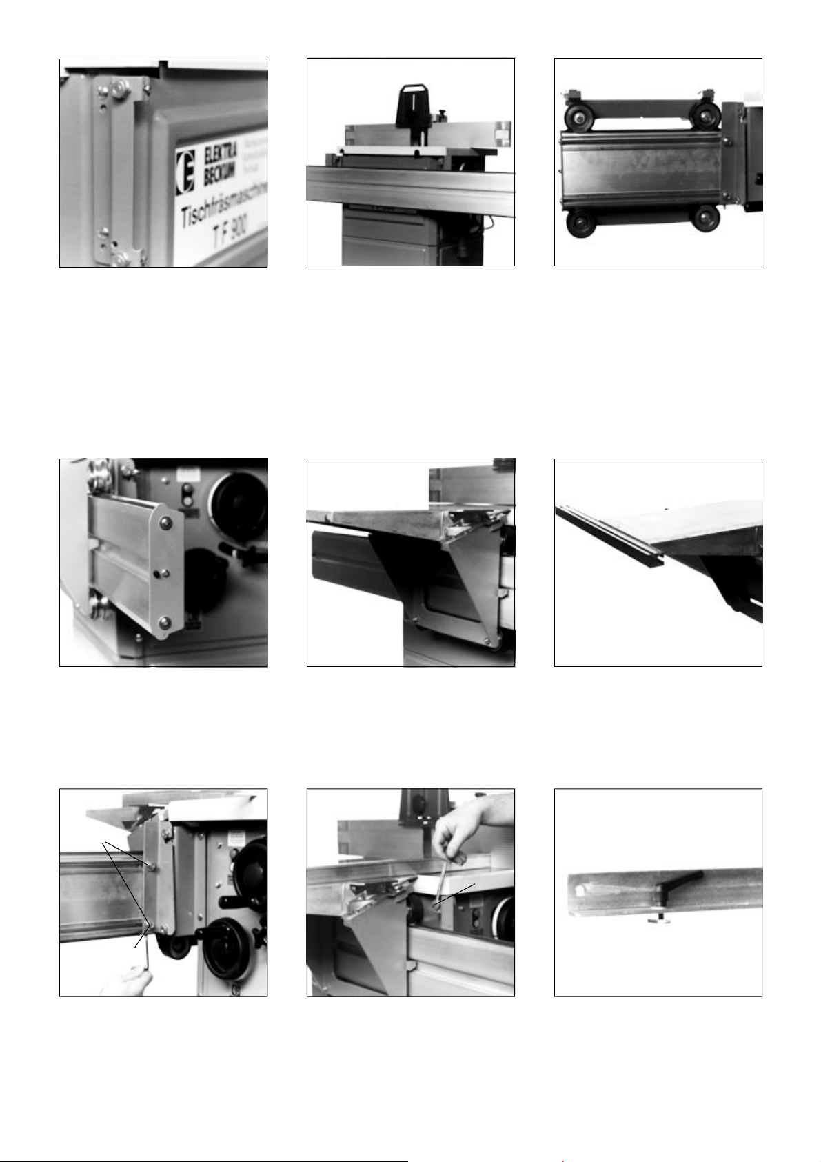
5 Installation
Fit the two crosshead plates (370/371) to
the machine housing.
Use 4 each
cup square neck bolt M 6x20
flange nut M 6
Hook roller carriage extrusion (358) with
both extrusion brackets (319 + 320) onto the
crosshead plates. If it is a tight fit remove
some paint from the slots in the extrusion
brackets.
Secure roller carriage extrusion by fixing the
rear extrusion bracket (319) to the crosshead
plate (371), to prevent unhooking.
Use 1 each
hexagen head bolt M 6x16
hexagon nut M 6
Remove the front backstop plate (360) and
slide traversing saddle onto the roller car-
riage extrusion.
The carriage table should be set approx.
0.5 mm higher than the machine table. Set
with setting screws B. Loosen screw
holding rear extrusion bracket (319/371
and 320/370) to bracket before turning
setting screw B and tighten after setting.
Make trial cut to verify proper setting. After
setting is completed, tighten all 4 nuts
(408) M8 (A).
Alignment:
Set roller carriage extrusion parallel to the
machine table with both front and rear set-
ting screws C. It does not matter if the
carriage table is higher or lower than the
machine table.
After successful parallel alignment tighten
the counter nuts on all 4 setting screws B.
Den Klemmhebel mit Unterlegscheibe durch
den Schlitz der Kulissenschiene führen und
den Stellgleiter aufschrauben.
C
B
A
Reinstall backstop plate. Place sliding carriage table onto traversing
saddle and secure with the lock levers.
Loosely fit two cup square neck screws M
6x20 with washer Ø6.4, spring washer Ø6
and hexagon nut M6 to the two holes in the
front of the carriage table.
Slide link bracket extrusion on the heads of
the just fitted cup square neck screws. At this
stage do not tighten the screws.
 Loading...