


 Loading...
Electrolux 9CHG584121, 9CHG584117, WHWUSFOOOO, 9CHG584115, 9CHG584116 User Manual
...thermaline S90
ELECTRIC FRY TOP, GRILL/GRIDDLE
PLAQUE CHAUFFANTE, PLAQUE GRIL ET GRIDDLE, ÉLECTRIQUE
US |
INSTALLATIONAND OPERATING INSTRUCTIONS |
page 3 |
FR |
INSTRUCTIONS D’INSTALLATION ET D’EMPLOI |
page 11 |
Doc. 62.9676.01_UL Edition 1
01.2006

Against wall - contre une paroi
Free standing - isolé
Connections - Raccordement
 Electricity - Electricité
Fig.1 INSTALLATION DRAWINGS - PLANS D'INSTALLATION
Doc. 62.9676.01_UL

CONTENTS |
|
|
I. |
GENERAL INFORMATION ................................................................................................. |
3 |
II. |
INSTALLATION INSTRUCTIONS ....................................................................................... |
4 |
III. |
OPERATING INSTRUCTIONS ............................................................................................ |
8 |
SOMMAIRE |
|
|
IV. |
INSTRUCTIONS GÉNÉRALES ......................................................................................... |
11 |
V. |
INSTRUCTIONS RELATIVES À L'INSTALLATION ......................................................... |
12 |
VI. |
INSTRUCTIONS DE FONCTIONNEMENT ....................................................................... |
16 |
62.9676.01_UL |
Page 1 |

Page 2 |
62.9676.01_UL |
GENERAL INFORMATION
I . GENERAL INFORMATION
1.INSTRUCTIONS FOR SAFETY AND USE
1.1INSTALLATION AND INITIAL OPERATION
S The installation, adjustment and initial operation of the appliance must be properly carried out in accordance with the manufacturer's instructions and may only be done by an authorised specialist.
SInstallations for the supply of electricity must be carried out by qualified installers in accordance with the specific national and local regulations. They bear the responsibility.
SThe appliance must not be placed in operation until the user has become familiar with its operation. The operating instructions and the related safety precautions must be followed precisely. Follow strictly the attention and warning label indications on the appliances.
1.2OWNER'S OBLIGATIONS
S The manager is responsible for ensuring that all components relevant for safety are in perfect working order at all times. The operating condition of these components must be examined by an authorized technician at least once a year and any defects remedied if required.
SThe operator of this appliance is responsible for total observation of the national regulations concerning operating safety.
SRemain the manual for future reference.
1.3USE AS PRESCRIBED
SClosed containers (jars, cans, bottles, tubes, etc.) must not be heated owing to the danger of bursting and injuries.
1.4SAFETY-CONSCIOUS WORKING
STouching the hot plates can cause burns.
SSpraying the appliance or its parts with a highpressure cleaning device may cause malfunctions and is not to be done.
SWhen putting oil, fat, water or ingredients in the preheated hot frying pan, they may spit. - Danger of burning!
SFilling quantity and temperature must be selected as appropriate. At high temperatures (above 100°C) too much liquid in the trough can lead to boiling over and spitting. - Danger of burning!
SOverheated oil can ignite spontaneously. Never use water to extinguish burning oil, but smother the flames with the lid or a damp cloth.
SFor appliances with a downpipe, the hose should lead into a drain opening which is covered by a grating such that it cannot be kicked or tipped, or a drain gutter should run underneath the appliance.
SDevices on wheels set up in block configuration must be checked before each start-up whether the potential equalization is connected with the neighbour equipment. The connection may be done only by authorized technical personnel.
SAppliances on wheels must be fastened to the building.
1.5AFTER-SALES SERVICE AND REPAIR
S In the event of a permanent fault which interferes with operation, the appliance must be switched off and disconnected from the power supply.
STo perform maintenance and repairs contact the factory, the factory representative or a local service company.
SRepair, maintenance work and other adjustments are only to be carried out by an authorized specialist. The valid local and national regulations must be observed. This applies especially to safety and control elements. Parts requiring replacement are only to be replaced by original spare parts. A service contract is recommended.
SCleaning and maintenance must be done only when the heating surfaces are cold. Do not use inflammable liquids to clean the appliance.
SAn obligatory service check is required annually.
2.TECHNICAL DATA
|
|
|
Width |
Cooking |
Power |
||
PNC |
Appliance type |
Voltage |
Depth |
surface |
|
||
Appliances |
|
Height |
|
|
|||
|
|
|
|
||||
|
|
V |
inch |
mm |
|
in kW |
|
|
|
|
|
|
|
|
|
9CHG584114 |
WHWURFOOOO |
208 |
|
|
|
11.4 |
|
|
|
|
|
|
|
|
|
9CHG584115 |
WHXURFOOOO |
240 |
|
|
|
13.2 |
|
|
|
|
|
|
|
|
|
9CHG584116 |
WHWUSFOOOO |
208 |
31.5 |
800 |
29.4“ x |
11.4 |
|
|
|
|
|
||||
9CHG584117 |
WHXUSFOOOO |
240 |
25.6“ |
13.2 |
|||
35.4 |
900 |
||||||
|
|
|
748 x |
|
|||
9CHG584118 |
WHWURAOOOO |
208 |
11.4 |
||||
35.4 |
900 |
||||||
|
|
|
649 mm |
|
|||
9CHG584119 |
WHXURAOOOO |
240 |
|
|
13.2 |
||
|
|
|
|||||
|
|
|
|
|
|
|
|
|
|
|
|
|
|
||
9CHG584120 |
|
|
|
11.4 |
|||
WHWUSAOOOO |
208 |
|
|
|
|||
|
|
|
|
|
|
|
|
9CHG584121 |
WHXUSAOOOO |
240 |
|
|
|
13.2 |
|
|
|
|
|
|
|
|
|
3.PACKAGING
All the packaging materials used are environmentally friendly. They may burnt at an incineration plant or sent for recycling.
4.TESTS / CERTIFICATES
All electrical appliances are UL 197 tested.
The appliance noise level is negligibly low. The statutory guidelines are met; the noise level is less than 70 dB (A).
5.SPECIFICATION PLATE
The specification plate (E) is located in each case inside and outside on the right of the operator panel (C) (Page 5 Fig. 5).
The serial number is marked on the type plate. The 8 digits give following information:
Y |
last digit of the year of production |
WW |
week of production |
XXXXX |
running number |
62.9676.01_UL |
Page 3 |
INSTALLATION INSTRUCTIONS
II . INSTALLATION INSTRUCTIONS
1. |
INSTALLATION |
1.3 |
ASSEMBLING TWO APPLIANCES |
The appliance is designed for connection to fixed lines. The appliances are suitable for setting up as single appliances or as a group of appliances. They can be set up freely in the room, side by side, at the side and/or at the back against a wall.
Gaps between two appliances or appliance and sidewall should be filled with a FDA approved silicone such as Samco RTV103.
1.1DISTANCES
If an appliance is set up next to or against temperature-sensi- tive furniture or similar, a safety gap of approximately 6“ (15 mm) should be maintained or some form of heat insulation fitted.
The walls must be made up of non-combustible material like tiles or steel.
1.2HEIGHT ADJUSTMENT
Appliance on feet: Alignment is carried out by screwing the lower foot parts in or out.
Appliance on |
Irregularities or differences in height can |
steel plinth: |
be equalized by inserting one or several |
|
strips of chrome nickel steel. |
Appliance on feet.
D Turn the lower part of the feed to adjust the appliance high.
The feet are adjustable from 4“ to 8“ (100 to 200 mm). A high of 8“ (200 mm) can be recommended and results in an appliance high of 35,4“ (900 mm).
Note:
Adjustment of the legs shall provide an unobstructed clearance of minimal 6“ (150 mm) and maximal 8“ (200 mm) beneath the unit due to sanitary and stability aspects.
The lower part of the foot must not be unscrewed too far. The exposure of threads is prohibited.
(1)
(1)
(3)
(2)
(2)
a
b
c
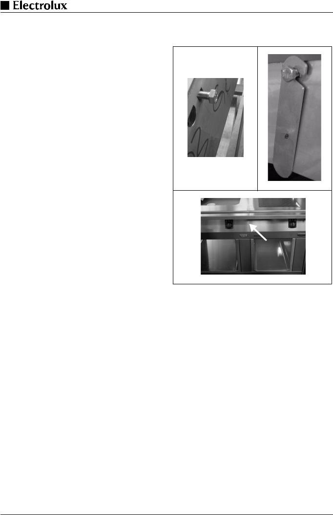
Fig.1 Lateral connection
The assembly kit contains three of each of the following:
caged nuts (1 / Fig.1) pre-assembled on the right-hand side of the appliance, hexagonal screws M8x25 (1 / Fig.1), bolts with retaining rings (2 / Fig.1) and mounting links (3 / Fig.1)
DRemove the control panels from both appliances as in 2.2
DRemove the front panels from both appliances as in 2.1
DInsert the bolts with the retaining rings (2 / Fig.1) from outside into the guide in the right-hand connecting plate.
DKeeping the screw (3 / Fig.1) loose, turn it until it is approximately 5 mm deep in the caged nut.
Positioning the appliances:
DPlace the appliances next to one other.
DAlign for position and height.
Connect the appliances:
DPush the appliances together so that the bolts (1 / Fig.1) engage in the guides of the appliance to be attached.
DFit the mounting link (3 / Fig.1) into the inside of the second appliance's left connecting plate.
DTighten the screws.
Note
If required, the caged nuts can also be fitted on the other side of the appliance.
The connection of two appliances (Fig 1c, arrow) must correspond to the hygienic regulations respective the standard NSF/ANSI 4. All resulting joints and seams in a splash zone shall be sealed and smooth.
Page 4 |
62.9676.01_UL |
Loading...