


DL 4150 CHDL 4150 DL 6250 570 D 5708 D
Cooker Hood Cappa aspirante Campana extractora
Operating and Installation Instructions Istruzioni di montaggio ed uso Instrucciones de montaje y manejo

Contents
Safety warnings |
3 |
For the user |
3 |
For the installer |
3 |
Description of the Appliance |
5 |
Extractor version |
5 |
Filter Version |
5 |
Control Panel |
6 |
Maintenance and care |
7 |
Cleaning the hood |
7 |
Metal grease filter |
7 |
Removing the metal grease filter |
7 |
Charcoal filter |
9 |
Changing the light bulb |
10 |
What to do if |
11 |
Special accessories |
12 |
Technical assistance service |
12 |
Technical Specifications |
13 |
Electrical connection |
14 |
Installation |
15 |
Removing the hood from cabinet |
17 |
Relocating the control unit (Only 570 D - 5708 D) |
18 |
Printed on recycled paper
AEG - putting words into action
2

Safety warnings
For the user
•The cooker hood is designed to extract unpleasant odours from the kitchen, it will not extract steam.
•Always cover lighted elements, to prevent excess heat from damaging the appliance. In the case of oil, gas and coal fired cookers it is essential to avoid open flames.
•Also, when frying, keep the deep frying pan on the cooker top/ cooker under careful control.
•The hot oil in the frying pan might ignite due to overheating.
•The risk of self-ignition increases when the oil being used is dirty.
•It is extremely important to note that overheating can cause a fire.
•Never carry out any flambé cooking under the hood.
•Always disconnect the unit from the power supply before carrying out any work on the hood, including replacing the light bulb (take the cartridge fuse out of the fuse holder or switch off the automatic circuit breaker).
•It is very important to clean the hood and replace the filter at the recommended intervals. Failure to do so could cause grease deposits to build up, resulting in a fire hazard.
For the installer
•When used as an extractor unit, the hood must be fitted with a 120mm diameter hose.
•When installing the hood, make sure you respect the following minimum distance from the top edge of the cooking hob/ring surfaces:
electric cookers |
650 mm |
gas cookers |
750 mm |
coal and oil cookers |
800 mm min. |
•The national standard on fuel-burning systems specifies a maximum depression of 0.04 bar in such rooms.
•The air outlet must not be connected to chimney flues or combustion gas ducts. The air outlet must under no circumstances be connected to ventilation ducts for rooms in which fuel-burning appliances are installed.
•The air outlet installation must comply with the regulations laid down by the relevant authorities.
•When the unit is used in its extractor version, a sufficiently large ventilation hole must be provided, with dimensions that are
3

approximately the same as the outlet hole.
•National and regional building regulations impose a number of restrictions on using hoods and fuel-burning appliances connected to a chimney, such as coal or oil room-heaters and gas fires, in the same room.
•Hoods can only be used safely with appliances connected to a chimney if the room and/or flat (air/environment combination) is ventilated from outside using a suitable ventilation hole approximately 500-600 cm2 large to avoid the possibility of a depression being created during operation of the hood.
•If you have any doubts, contact the relevant controlling authority or building inspector’s office.
•Since the rule for rooms with fuel burning appliances is “outlet hole of the same size as the ventilation hole”, a hole of 500-600 cm2, which is to say a larger hole, could reduce the performance of the extractor hood.
•If the hood is used in its filtering function, it will operate simply and safely in the above conditions without the need for any of the aforementioned measures.
•When the hood is used in its extractor function, the following rules must be followed to obtain optimal operation:
—short and straight outlet hose
—keep bends in outlet hose to a minimum
—never install the hoses with an acute angle, they must always
follow a gentle curve.
—keep the hose as large as possible (preferably the same diameter as the outlet hole).
•Failure to observe these basic instructions will drastically reduce the performance and increase the noise levels of the extractor hood.
4

Description of the Appliance
•The hood is supplied as an extractor unit and can also be used with a filtering function by fitting one charcoal filter.
•You will need an original AEG charcoal filter for this function (Available from your local AEG Service Force Centre).
Extractor version
•In this version fumes are extracted to the outside via a hose connected to the coupling ring. Fig. 1.
•In order to obtain the best performance the hose should have a diameter equal to the outlet hole.
Only for model DL 4150-CHDL 4150:
Should there already be an hose of diameter 100 mm that ducts to the outside through the walls or roof, it is possible to use the 120/ 100 mm adapter. In this case the hood will be slightly noisier.
Coupling ring
510
710
Bayonet screw fitting (Only 570 D - 5708 D)
Fig. 1
Filter Version
• The air is filtered through a charcoal filter and returned to the kitchen. Fig. 2.
• You will need an original AEG charcoal filter for the filtering function. (See Special Accessories).
Fig. 2
5
Control Panel
•Best results are obtained by using a low speed for normal conditions and a high speed when odours are more concentrated. Turn the hood on a few minutes before you start cooking, you will then get an under pressure in the kitchen. The hood should be left on after cooking for about 15 minutes or until all the odours have disappeared.
The switches are located on the right-hand side of the hood.
•the light switch switches the hood lamp on and off
•the motor switch switches the motor on and off, enabling you to select one of the three different speeds.
DL 4150
CHDL 4150
Light switch
0 = Light OFF
1 = Light ON
Motor switch
0 = Motor OFF
1 = Speed 1 - Slow
2 = Speed 2 - Medium
3 = Speed 3 - Fast
Fig. 3
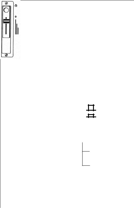
DL 6250 570 D 5708 D
Light switch
= Light OFF
= Light ON
Motor switch
= Sliding speed control
i
Booster 1
(Only 570 D)
Booster 1+2
(Only 5708 D)
6
 Loading...