


ARF PA-20 Pacer 10e
ALMOST-READY-TO-FLY
Instruction Manual
Bedienungsanleitung
Manuel d’utilisation
Manuale di Istruzioni
1

NOTICE
All instructions, warranties and other collateral documents are subject to change at the sole discretion of Horizon Hobby, Inc. For up-to-date product literature, visit horizonhobby. com and click on the support tab for this product.
Meaning of Special Language
The following terms are used throughout the product literature to indicate various levels of potential harm when operating this product:
NOTICE: Procedures, which if not properly followed, create a possibility of physical property damage AND a little or no possibility of injury.
CAUTION: Procedures, which if not properly followed, create the probability of physical property damage AND a possibility of serious injury.
WARNING: Procedures, which if not properly followed, create the probability of property damage, collateral damage, and serious injury OR create a high probability of superfi cial injury.
WARNING: Read the ENTIRE instruction manual to become familiar with the features of the product before operating. Failure to operate the product correctly can result in damage to the product, personal property and cause serious injury.
This is a sophisticated hobby product. It must be operated with caution and common sense and requires some basic mechanical ability. Failure to operate this Product in a safe and responsible manner could result in injury or damage to the product or other property. This product is not intended for use by children without direct adult supervision. Do not use with incompatible components or alter this product in any way outside of the instructions provided by Horizon Hobby, Inc. This manual contains instructions for safety, operation and maintenance. It is essential to read and follow all the instructions and warnings in the manual, prior to assembly, setup or use, in order to operate correctly and avoid damage or serious injury.
Age Recommendation: Not for children under 14 years. This is not a toy.
USING THE MANUAL
This manual is divided into sections to help make assembly easier to understand. Boxes () have been placed next to each step. These help keep track of steps that have been completed.
SAFETY WARNINGS AND PRECAUTIONS
Read and follow all instructions and safety precautions before use. Improper use can result in fi re, serious injury and damage to property.
Components
Use only with compatible components. Should any compatibility questions exist, please refer to the product instructions, component instructions or contact the appropriate Horizon Hobby offi ce.
Flight
Fly only in open areas to ensure safety. It is recommended fl ying be done at radio control fl ying
fi elds. Consult local ordinances before choosing a fl ying location.
Propeller
Keep loose items that can become entangled in the propeller away from the prop. This includes loose clothing or other objects such as pencils and
screwdrivers. Keep your hands away from the propeller as injury can occur.
Batteries
Always follow the manufacturer’s instructions when using and disposing of any batteries. Mishandling of Li-Po batteries can result in fi re causing serious injury and damage.
Small Parts
This kit includes small parts and should not be left unattended near children as choking and serious injury could result.
SAFE OPERATING RECOMMENDATIONS
•Inspect your model before every fl ight to ensure it is airworthy.
•Be aware of any other radio frequency user who may present an interference problem.
•Always be courteous and respectful of other users in your selected fl ight area.
•Choose an area clear of obstacles and large enough to safely accomodate your fl ying activity.
•Make sure this area is clear of friends and spectators prior to launching your aircraft.
•Be aware of other activities in the vicinity of your fl ight path that could cause potential confl ict.
•Carefully plan your fl ight path prior to launch.
•Abide by any and all established AMA National Model Aircraft Safety Code.
2

HINWEIS
Alle Anweisungen, Garantien und anderen zugehörigen Dokumente können im eigenen Ermessen von Horizon Hobby, Inc. jederzeit geändert werden. Die aktuelle Produktliteratur fi nden Sie auf horizonhobby.com unter der Registerkarte „Support“ für das betreffende Produkt.
Spezielle Bedeutungen
Die folgenden Begriffe werden in der gesamten Produktliteratur verwendet, um auf unterschiedlich hohe Gefahrenrisiken beim Betrieb dieses Produkts hinzuweisen:
HINWEIS: Wenn diese Verfahren nicht korrekt befolgt werden, können sich möglicherweise Sachschäden UND geringe oder keine Gefahr von Verletzungen ergeben.
ACHTUNG: Wenn diese Verfahren nicht korrekt befolgt werden, ergeben sich wahrscheinlich Sachschäden UND die Gefahr von schweren Verletzungen.
WARNUNG: Wenn diese Verfahren nicht korrekt befolgt werden, ergeben sich wahrscheinlich Sachschäden, Kollateralschäden und schwere Verletzungen ODER mit hoher Wahrscheinlichkeit oberfl ächliche Verletzungen.
WARNUNG: Lesen Sie die GESAMTE Bedienungsanleitung, um sich vor dem Betrieb mit den Produktfunktionen vertraut zu machen. Wird das Produkt nicht korrekt betrieben, kann dies zu Schäden am
Produkt oder persönlichem Eigentum führen oder schwere Verletzungen verursachen.
Dies ist ein hochentwickeltes Hobby-Produkt. Es muss mit Vorsicht und gesundem Menschenverstand betrieben werden und benötigt gewisse mechanische Grundfähigkeiten. Wird dieses Produkt nicht auf eine sichere und verantwortungsvolle Weise betrieben, kann dies zu Verletzungen oder Schäden am Produkt oder anderen Sachwerten führen. Dieses Produkt eignet sich nicht für die Verwendung durch Kinder ohne direkte Überwachung eines Erwachsenen. Verwenden Sie das Produkt nicht mit inkompatiblen Komponenten oder verändern es in jedweder Art ausserhalb der von Horizon Hobby, Inc. vorgegebenen Anweisungen. Diese Bedienungsanleitung enthält Anweisungen für Sicherheit, Betrieb und Wartung. Es ist unbedingt notwendig, vor Zusammenbau, Einrichtung oder Verwendung alle Anweisungen und Warnhinweise im Handbuch zu lesen und zu befolgen, damit es bestimmungsgemäß betrieben werden kann und Schäden oder schwere Verletzungen vermieden werden.
Nicht geeignet für Kinder unter 14 Jahren. Dies ist kein Spielzeug.
ÜBER DIESE ANLEITUNG
Diese Anleitung ist zur Vereinfachung des Zusammenbaues in Sektionen unterteilt. Neben den Sektionen befi nden sich Kästchen () die es Ihnen leichter machen den Arbeitsschritt als erledigt abzuhaken.
WARNUNGEN UND SICHERHEITSVORKEHRUNGEN
Bitte lesen und befolgen Sie alle Anweisungen und Sichervorkehrungen vor dem Gebrauch. Falscher, nicht sachgemäßer Gebrauch kann Feuer, ernsthafte
Verletzungen und Sachbeschädigungen zur Folge haben.
Komponenten
Verwenden Sie mit dem Produkt nur kompatible Komponenten. Sollten Fragen zur Kompatibilität auftreten, lesen Sie bitte die Produktoder Bedienungsanweisung oder kontaktieren den Service von Horizon Hobby.
Fliegen
Fliegen Sie um Sicherheit garantieren zu können, nur in weiten offenen Gegenden. Wir empfehlen hier den Betrieb auf zugelassenen Modellfl ugplätzen. Bitte
beachten Sie lokale Vorschriften und Gesetze, bevor Sie einen Platz zum Fliegen wählen.
Propeller
Halten Sie lose Gegenstände die sich im Propeller verfangen können weg vom Propeller. Dieses gilt auch für Kleidung oder andere Objekte wie zum Beispiel Stifte oder Schraubendreher.
Halten Sie ihre Hände weg vom Propeller, es besteht akute Verletzungsgefahr.
Akkus
Folgen Sie immer den Herstelleranweisungen bei dem Gebrauch oder Entsorgung von Akkus. Falsche Behandlung von Li-Po Akkus kann zu Feuer mit Körperverletzungen und Sachbeschädigung führen.
Kleinteile
Dieser Baukasten beinhaltet Kleinteile und darf nicht unbeobachtet in der Nähe von Kindern gelassen werden, da die Teile verschluckt werden könnten mit ernsthaften Verletzung zur Folge.
EMPFEHLUNGEN ZUM SICHEREN BETRIEB
•Überprüfen Sie zur Flugtauglichkeit ihr Modell vor jedem Flug.
•Beachten Sie andere Piloten deren Sendefrequenzen ihre Frequenz stören könnte.
•Begegnen Sie anderen Piloten in ihrem Fluggebiet immer höfl ich und respektvoll.
•Wählen Sie ein Fluggebiet, dass frei von Hindernissen und groß genug ist.
•Stellen Sie vor dem Start sicher, dass die Fläche frei von Freunden und Zuschauern ist.
•Beobachten Sie den Luftraum und andere Flugzeuge/ Objekte die ihren Flugweg kreuzen und zu einem Konfl ikt führen könnten.
•Planen Sie sorgfältig ihren Flugweg vor dem Start.
3

REMARQUE
La totalité des instructions, garanties et autres documents est sujette à modifi cation à la seule discrétion d’Horizon Hobby, Inc. Pour obtenir la documentation à jour, rendez-vous sur le site horizonhobby.com et cliquez sur l’onglet de support de ce produit.
Signifi cation de certains termes spécifi ques
Les termes suivants sont utilisés dans l’ensemble du manuel pour indiquer différents niveaux de danger lors de l’utilisation de ce produit:
REMARQUE: Procédures qui, si elles ne sont pas suivies correctement, peuvent entraîner des dégâts matériels ET éventuellement un faible risque de blessures.
ATTENTION: Procédures qui, si elles ne sont pas suivies correctement, peuvent entraîner des dégâts matériels ET des blessures graves.
AVERTISSEMENT: Procédures qui, si elles ne sont pas suivies correctement, peuvent entraîner des dégâts matériels et des blessures graves OU engendrer une probabilité élevée de blessure superfi cielle.
AVERTISSEMENT: Lisez la TOTALITÉ du manuel d’utilisation afi n de vous familiariser avec les caractéristiques du produit avant de le faire fonctionner. Une utilisation incorrecte du produit peut entraîner
sa détérioration, ainsi que des risques de dégâts matériels, voire de blessures graves.
Ceci est un produit de loisirs sophistiqué. Il doit être manipulé avec prudence et bon sens et requiert des aptitudes de base en mécanique. Toute utilisation irresponsable de ce produit ne respectant pas les principes de sécurité peut provoquer des blessures, entraîner des dégâts matériels et endommager le produit. Ce produit n’est pas destiné à être utilisé par des enfants sans la surveillance directe d’un adulte. N’essayez pas de modifi er ou d’utiliser ce produit avec des composants incompatibles hors des instructions fournies par Horizon Hobby, Inc. Ce manuel comporte des instructions relatives à la sécurité, au fonctionnement et à l’entretien. Il est capital de lire et de respecter la totalité des instructions et avertissements du manuel avant l’assemblage, le réglage et l’utilisation, ceci afi n de manipuler correctement l’appareil et d’éviter tout dégât matériel ou toute blessure grave.
14 ans et plus. Ceci n’est pas un jouet.
UTILISATION DU MANUEL
Ce manuel est divisé en sections pour vous aider à comprendre plus facilement l’assemblage. Des cases () ont été placées à chaque étape. Cela vous permet d’avoir un suivi des étapes déjà effectuées.
AVERTISSEMENTS RELATIFS À LA SÉCURITÉ
Lisez et suivez toutes les instructions relatives à la sécurité avant utilisation. Une utilisation inappropriée peut entraîner un incendie, de graves blessures et des dégâts matériels.
Composants
Utilisez uniquement des composants compatibles. Si vous avez des questions concernant la compatibilité, référez-vous à ce manuel ou contactez le service technique Horizon Hobby.
Le vol
Volez uniquement dans des zones dégagées pour un maximum de sécurité. Il est recommandé d’utiliser les pistes des clubs d’aéromodélisme. Consultez votre mairie pour connaître les sites autorisés.
L’hélice
Gardez éloignés tous les éléments qui pourraient être attrapés par l’hélice. Cela inclut les vêtements larges ou les objets comme des outils par exemple. Gardez toujours vos mains à distance pour éviter tout cas de blessures.
Les batteries
Suivez toujours les instructions du fabricant de vos batteries. Une mauvaise manipulation d’une batterie LiPo peut entraîner un incendie causant de graves dégâts matériels et des blessures corporelles.
Petites pièces
Ce kit contient des petites pièces qui ne doivent pas être laissées à la portée des enfants, ces pièces sont dangereuses pour eux et peuvent entraîner de graves blessures.
CONSIGNES DE SÉCURITÉ CONCERNANT L’UTILISATION
•Inspectez votre modèle avant chaque vol.
•Surveillez les fréquences utilisées à proximité.
•Soyez toujours courtois et respectueux des autres utilisateurs de la zone de vol.
•Choisissez une zone dégagée de tout obstacle et suffi samment grande pour voler en toute sécurité.
•Contrôlez que la zone est libre de spectateurs avant de lancer votre modèle.
•Soyez conscient des autres activités aux alentours de votre vol, pour éviter tout confl it potentiel.
•Planifi ez votre vol avant de le commencer.
4

AVVISO
Tutte le istruzioni, le garanzie e gli altri documenti pertinenti sono soggetti a cambiamenti a totale discrezione di Horizon Hobby, Inc. Per una documentazione aggiornata sul prodotto, visitare il sito www.horizonhobby.com e fare clic sulla sezione Support per questo prodotto.
Signifi cato dei termini particolari
In tutta la documentazione relativa al prodotto sono utilizzati i seguenti termini per indicare vari livelli di potenziale pericolo durante il funzionamento:
AVVISO: Procedure che, se non sono seguite correttamente, possono creare danni materiali E nessuna o scarsa possibilità di lesioni.
ATTENZIONE: Procedure che, se non sono seguite correttamente, possono creare danni materiali E possibili gravi lesioni.
AVVERTENZA: Procedure che, se non debitamente seguite, espongono alla possibilità di danni alla proprietà fi sica o possono omportare un’elevata possibilità di provocare ferite superfi ciali. Ulteriori precauzioni per la sicurezza e avvertenze.
AVVERTENZA: Leggere TUTTO il manuale di istruzioni e prendere familiarità con le caratteristiche del prodotto, prima di farlo funzionare. Un utilizzo scorretto del prodotto può causare danni al prodotto stesso,
alle persone o alle cose, provocando gravi lesioni.
Questo è un prodotto di hobbistica sofi sticato e NON un giocattolo. È necessario farlo funzionare con cautela e responsabilità e avere conoscenze basilari di meccanica. Se questo prodotto non è utilizzato in maniera sicura e responsabile potrebbero verifi carsi lesioni o danni al prodotto stesso o ad altre proprietà. Non è un prodotto adatto a essere utilizzato dai bambini senza la diretta supervisione di un adulto. Non usare componenti non
compatibili o alterare il prodotto in nessuna maniera al di fuori delle istruzioni fornite da Horizon Hobby, Inc. Questo manuale contiene le istruzioni per un funzionamento e una manutenzione sicuri. È fondamentale leggere e seguire tutte le istruzioni e le avvertenze del manuale prima di montare, confi gurare o far funzionare il Prodotto, al fi ne di utilizzarlo correttamente e di evitare danni o lesioni gravi.
AVVERTIMENTI E PRECAUZIONI PER LA SICUREZZA
Prima dell’uso leggere attentamente tutte le istruzioni e le precauzioni per la sicurezza. In caso contrario si potrebbero procurare incendi, danni o ferite.
Componenti
Usare solo componenti compatibili. Se ci fossero dubbi riguardo alla compatibilità, è opportuno far riferimento alle istruzioni relative al prodotto o ai componenti oppure rivolgersi al reparto Horizon Hobby di competenza.
Volo
Per sicurezza volare solo in aree molto ampie. Meglio se si va su campi volo autorizzati per modellismo. Consultare le ordinanze locali prima di scegliere una ubicazione.
Elica
Tenere gli oggetti liberi (vestiti, penne, cacciaviti, ecc.) lontano dall’elica, prima che vi restino impigliati. Bisogna fare attenzione anche con le mani perché c’è il rischio di ferirsi anche gravemente.
Batterie
Quando si maneggiano o si utilizzano le batterie, bisogna attenersi alle istruzioni del costruttore; il rischio è di procurare incendi, specialmente con le batterie Li-Po, con danni e ferite serie.
Piccole parti
Questo kit comprende delle parti di piccole dimensioni e non lo si può lasciare incustodito se c’è la presenza di bambini che li possono inghiottire e rimanere soffocati o intossicati.
RACCOMANDAZIONI PER OPERARE IN SICUREZZA
•Controllare attentamente il modello prima di ogni volo per accertarsi che sia idoneo.
•Essere consapevoli che un altro utente della frequenza in uso, potrebbe procurare delle interferenze.
•Essere sempre cortesi e rispettosi nei confronti degli altri utilizzatori dell’area in cui ci si trova.
•Scegliere un’area libera da ostacoli e abbastanza ampia da permettere lo svolgimento del volo in sicurezza.
•Prima del volo verifi care che l’area sia libera da amici e spettatori.
•Stare attenti alle altre attività che si svolgono in vicinanza della vostra traiettoria di volo, per evitare possibili confl itti.
•Pianifi care attentamente il volo prima di lanciare il modello.
•Rispettare sempre scrupolosamente le regole stabilite dall’associazione locale.
Almeno 14 anni. Non è un giocattolo.
COME USARE IL MANUALE
Questo manuale è diviso in sezioni per rendere più facile la comprensione del montaggio. Vicino ad ogni passo sono stati posti dei piccoli quadrati () per aiutare a tenere traccia delle cose fatte e di quelle da fare.
5
SPECIFICATIONS•SPEZIFIKATIONEN•
SPÉCIFICATIONS•SPECIFICHE
51.0 in (1300mm)
451 sq in (29.1 dm2)
36.3 in (920mm)
46.4–48.0 oz (1300–1360 g)
Electric Power Power: Power 10 Brushless Elektro Antrieb Power: Power 10 Brushless Moteur électrique (EP): Power 10 Brushless Motore elettrico: Power 10 Brushless
4-channel (or greater) with 4–6 servos
4-Kanal (oder größer) mit 4–6 Servos
4 voies (ou plus) avec 4–6 servos a 4 canali (o più) con 4–6 servo
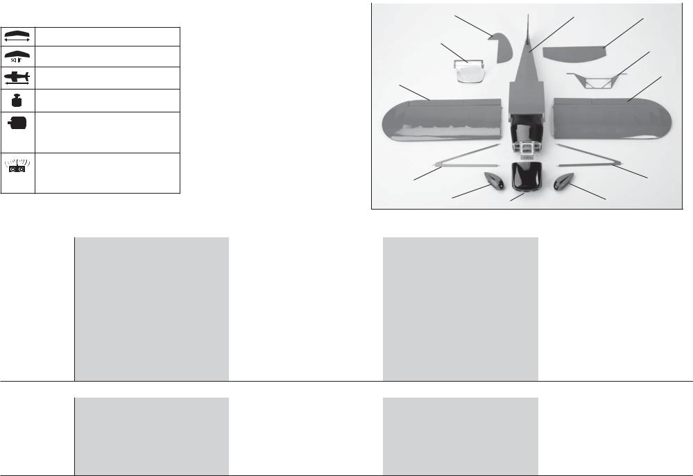
•LARGE PARTS LAYOUT |
3 |
|
|
•BAUTEILE (OHNE KLEINTEILE) |
1 |
3 |
|
•GRANDES PIÈCES |
|
|
|
•SCHEMA DEI COMPONENTI GRANDI |
|
|
|
|
7 |
|
5 |
|
|
|
|
|
|
|
2 |
|
2 |
|
|
8 |
|
8 |
6 |
4 |
6 |
REPLACEMENT PARTS•ERSATZTEILE•PIÈCES DE RECHANGE•RICAMBI |
|
|
|||
|
Part |
English |
Deutsch |
Français |
Italiano |
|
|
|
|
|
|
1. |
EFL279001 |
Fuselage |
Rumpf |
Fuselage |
Fusoliera |
|
|
|
|
|
|
2. |
EFL279002 |
Wing Set |
Tragfl ächenset |
Ailes |
Set ala |
|
|
|
|
|
|
3. |
EFL279003 |
Tail Set |
Heck |
Empennages |
Set coda |
|
|
|
|
|
|
4. |
EFL279004 |
Cowling |
Motorhaube |
Capot moteur |
Carenatura |
|
|
|
|
|
|
5. |
EFL279005 |
Landing Gear |
Fahrwerk |
Train d’atterrissage |
Carrello atterraggio |
|
|
|
|
|
|
6. |
EFL279006 |
Wheel Pants |
Radverkleidung |
Carénage de roue |
Copriruote |
|
|
|
|
|
|
7. |
EFL279009 |
Window Set |
Fenster Set |
Jeu de fenêtres |
Set fi nestrature |
|
|
|
|
|
|
8. |
EFL279010 |
Scale Accessory Package |
Scale Zubehör Paket |
Sachet d’accessoires maquette |
Pacchetto accessori in scala |
SMALL PARTS (NOT SHOWN)•KLEINTEILE (NICHT ABGEBILDET)•PETITES PIÈCES (NON REPRÉSENTÉES)•PARTI DI PICCOLE DIMENSIONI (NON MOSTRATE)
EFL279007 |
Pushrod Set |
Gestänge / Anlenkungen Set |
Jeu de tringleries |
Set dell’asta di spinta |
|
|
|
|
|
EFL279008 |
Battery Hatch |
Akkuklappe |
Trappe à batterie |
Portello batteria |
|
|
|
|
|
EFL279011 |
Hardware Set |
Kleinteile Set |
Sachet de visserie |
Set dei pezzi |
|
|
|
|
|
EFL279012 |
Wing Tube |
Tragfl ächenverbinder |
Clé d’aile |
Tubo dell’ala |
|
|
|
|
|
EFL279013 |
Decal Set |
Dekorbogen |
Planche de décoration |
Set di decalcomanie |
6

REQUIRED RADIO |
EQUIPMENT•ERFORDERLICHE RC |
AUSRÜSTUNG•EQUIPEMENT RADIO |
REQUIS•APPARECCHIATURE RADIO |
|
Part |
English |
Deutsch |
Français |
Italiano |
SPMAR600 |
AR600 Full-Range Sport Receiver |
AR 600 Sport Empfänger mit voller Reichweite |
Récepteur longue portée AR600 Sport |
Ricevitore sport AR600 a piena portata |
EFLRDS76 (4)* |
7.6-Gram DS76 Digital Sub-Micro Servo |
7.6-Gram DS76 Digital Sub-Micro Servo |
Sub micro servo digital 7.6g DS76 |
7.6-Gram DS76 Digital Sub-Micro Servo |
EFLREX3L (2) |
3-inch Extension, Lightweight |
75mm Servokabelverlängerung extraleicht |
Rallonge de servo, légère 75mm |
Prolunga, leggera 75mm |
EFLREX9L (4) |
9-inch Extension, Lightweight |
230mm Servokabelverlängerung extraleicht |
Rallonge de servo, légère 230mm |
Prolunga, leggera 230mm |
EFLRYH3 (2) |
3-inch Y-Harness |
3 inch Y-Kabel |
Cordon Y, 75mm |
Prolunga a Y da 75mm |
POWER |
SYSTEM•ANTRIEB•MOTORISATION•SISTEMA |
PROPULSIVO |
|
|
EFLM4010A |
Power 10, 1100Kv |
Power 10, 1100Kv |
Power 10, 1100Kv |
Power 10, 1100Kv |
EFLA1040L |
40-Amp Lite Pro Switch-Mode BEC Brushless ESC |
40A Lite Pro Switch-Mode Brushless Regler |
Contrôleur Brushless 40A Lite Pro |
Regolatore elettronico di velocità (ESC) Lite Pro da |
|
|
|
Swtich Mode BEC |
40A per motori brushless con BEC del tipo a |
|
|
|
|
commutazione |
EFLB18003S30 |
1800mAh 3S 11.1V 30C Li-Po |
1800mAh 3S 11.1V 30C Li-Po |
Batterie Li-Po 3S 11.1V 1800mA |
1800mAh 3S 11.1V 30C Li-Po |
APC11070E |
Electric Propeller, 11 x 7E |
Elektro Propeller, 11 x 7E |
Hélice électrique, 11 x 7E |
Elica elettrica sottile, 11 x 7E |
EFLSP175 |
1.75-inch Aluminum Spinner with |
E-fl ite Aluminiumspinner 44mm mit |
Cône aluminium 44mm avec adaptateurs 4 et 6mm |
Ogiva alluminio da 45mm con adattatori |
|
4mm and 6mm Collets |
4/5mm Adapter |
|
da 4 e 6mm |
REQUIRED |
ADHESIVES•ERFORDERLICHE KLEBSTOFFE•TYPES DE COLLES•ADESIVI NECESSARI |
|
|
|
PAAPT09 |
Thin CA |
Sekundenkleber dünnfl üssig |
Colle cyano fi ne |
Sottile CA |
PAAPT03 |
Medium CA |
Sekundenkleber mittel |
Colle cyano moyenne |
Medio CA |
PAAPT42 |
Threadlock |
Schraubensicherungslack |
Frein-fi let |
Frenafi letti |
PAAPT38 |
5-Minute Epoxy |
5 Minuten Epoxy |
Époxy 5 minutes |
Colla epoxy 5 minuti |
OPTIONAL ITEMS•OPTIONALE TEILE•ELÉMENTS OPTIONNELS•ARTICOLI OPZIONALI |
|
|
||
EFLRDS76 (2) |
7.6-Gram DS76 Digital Sub-Micro Servo |
7.6-Gram DS76 Digital Sub-Micro Servo |
Sub micro servo digital 7.6g DS76 |
7.6-Gram DS76 Digital Sub-Micro Servo |
|
(Optional operational fl aps) |
(Optionale Landeklappen) |
(Volets fonctionnels optionnels) |
(Flap operativi opzionali) |
EFLA110 |
Power Meter |
E-fl ite Lastmessgerät |
Wattmètre |
Misuratore di potenza |
EFLC3020 |
Celectra™ 200W DC Charger |
E-fl ite 200W DC Multi-Akku Ladegerät |
Chargeur CC 200W Celectra |
Celectra 200W DC Caricabatterie |
*Two additional servos will be required for the optional operational fl aps. *Für die optionale Klappenfunktion sind zwei zusätzliche Servos erforderlich.
*2 servos supplémentaires seront requis pour l’utilisation des volets fonctionnels. *Per rendere i fl ap operativi, sono necessari altri due servi.
7

REQUIRED TOOLS•BENÖTIGTES WERKZEUG•OUTILS REQUIS•ATTREZZI NECESSARI
English |
Deutsch |
Français |
Italiano |
Box wrench: 10mm |
Ringschlüssel: 10mm |
Clé plate fermée 10mm |
Chiave a tubo: 10mm |
|
|
|
|
Drill bit: 1/16-inch, 5/64-inch, 1/8-inch |
Bohrer: 1,5 mm, 2mm, 3mm |
Foret : 1,5 mm, 2mm, 3mm |
Punte per trapano: 1,5 mm, 2mm, 3mm |
|
|
|
|
Felt-tipped pen |
Faserstift |
Feutre fi n effaçable |
Pennarello |
|
|
|
|
Hemostat |
Klemme |
Pince Hemostat |
Pinzetta |
|
|
|
|
Hex wrench: 3/32-inch, 1.5mm, 2mm, 2.5mm |
Inbusschlüssel: 3/32-inch, 1.5mm, 2mm, 2.5mm |
Tournevis hexagonal : 3/32-inch, 1.5mm, 2mm, 2.5mm |
Chiave esag.: 3/32-inch, 1.5mm, 2mm, 2.5mm |
|
|
|
|
Hobby and craft square |
Rechteck |
Equerre de modélisme |
Riga a squadra |
|
|
|
|
Hobby knife: #11 blade |
Hobbymesser mit # 11 Klinge |
Couteau : Lame numéro 11 |
Taglierino: #11 lama |
|
|
|
|
Pencil |
Stift |
Crayon à papier |
Matita |
|
|
|
|
Phillips screwdriver: #0, #1, #2 |
Phillips Schraubendreher: #0, #1, #2 |
Tournevis cruciforme: #0, #1, #2 |
Cacciavite a croce: #0, #1, #2 |
|
|
|
|
Pin vise |
Handbohrer |
Porte-forets |
Trapano manuale |
|
|
|
|
Pliers |
Zange |
Pince |
Pinze |
|
|
|
|
Propeller reamer |
Propellerfeile |
Alésoir d’hélice |
Alesatore per eliche |
|
|
|
|
Ruler |
Lineal |
Réglet |
Righello |
|
|
|
|
Sandpaper |
Schleifpapier |
Papier de verre |
Carta vetrata |
|
|
|
|
Scissors |
Schere |
Ciseaux |
Forbici |
|
|
|
|
Side cutters |
Seitenschneider |
Pince coupante |
Lama laterale |
|
|
|
|
Toothpicks |
Zahnstocher |
Cure dents |
Stuzzicadenti |
|
|
|
|
T-pins |
T- Nadeln |
Epingles |
Spilli a T |
|
|
|
|
8

BEFORE STARTING ASSEMBLY
•Remove parts from bag.
•Inspect fuselage, wing panels, rudder and stabilizer for damage.
•If you fi nd damaged or missing parts, contact your place of purchase.
If you fi nd any wrinkles in the covering, use a heat gun (HAN100) and covering glove (HAN150) or covering iron (HAN101) with a sealing iron sock (HAN141) to remove them. Use caution while working around areas where the colors overlap to prevent separating the colors.
This model has been designed to keep the weight at a minimum. When tightening the covering, work carefully to avoid inducing warps or changing the alignment of the structure.
•Charge transmitter and receiver batteries.
•Center trims and sticks on your transmitter.
•For a computer radio, create a model memory for this particular model.
•Bind your transmitter and receiver, using your radio system’s instructions.
IMPORTANT: Rebind the radio system once all control throws are set. This will keep the servos from moving to their endpoints until the transmitter and receiver connect. It will also guarantee the servo reversal settings are saved in the radio system.
VOR DEM ZUSAMMENBAU
•Entnehmen Sie zur Überprüfung jedes Teil der Verpackung.
•Überprüfen Sie den Rumpf, Tragfl ächen, Seitenund Höhenruder auf Beschädigung.
•Sollten Sie beschädigte oder fehlende Teile feststellen, kontaktieren Sie bitte den Verkäufer.
Zum Entfernen von Falten in der Bespannung verwenden Sie den Heißluftfön (HAN100) und Bespannhandschuh (HAN150) oder das Folienbügeleisen (HAN141). Bitte achten Sie bei überlappenden Farben, dass Sie diese sich bei dem Bearbeitung nicht trennen.
Dieses Modell wurde auf geringstes Gewicht konstruiert. Bitte beachten Sie bei dem Spannen der Bespannfolie, dass sie nicht die Ausrichtung der Struktur verändern.
•Laden des Senders und Empfängers.
•Zentrieren der Trimmungen und Sticks auf dem Sender.
•Sollten Sie einen Computersender verwenden, resetten Sie einen Speicherplatz und benennen ihn nach dem Modell.
•Sender und Empfänger jetzt nach den Bindeanweisung des Herstellers zu binden.
WICHTIG: Wir empfehlen dringend nachdem alle Einstellungen vorgenommen worden sind, das Modell neu zu binden. Dieses verhindert, dass die Servos
in die Endanschläge laufen bevor sich Sender und Empfänger verbunden haben. Es garantiert auch, dass die Servoreverseeinstellungen in der RC Anlage gesichert sind.
AVANT DE COMMENCER
L’ASSEMBLAGE
•Retirez toutes les pièces des sachets pour les inspecter.
•Inspectez soigneusement le fuselage, les ailes et les empennages.
•Si un élément est endommagé, contactez votre revendeur.
Si l’entoilage présente des plis, vous pouvez les lisser en utilisant le pistolet à air chaud (HAN100) et le gant (HAN150) ou le fer à entoiler (HAN101) avec la chaussette de protection (HAN141). Agissez soigneusement dans les zones où plusieurs couleurs
d’entoilage sont superposées afi n d’éviter de les séparer.
Ce modèle a été conçu pour obtenir une masse minimale. Quand vous retendez l’entoilage, prenez soin de ne pas déformer la structure.
•ll est recommandé de préparer tous les éléments du système de la radio.
•Cela inclut, la charge des batteries comme la mise au neutre des trims et des manches de votre émetteur.
•Si vous utilisez une radio programmable, sélectionnez une mémoire libre afi n d’y enregistrer les paramètres de ce modèle.
•Nous vous recommandons d’affecter maintenant le récepteur à l’émetteur en suivant les instructions fournies avec votre radio.
IMPORTANT: Il est hautement recommandé de ré-affecter le système une fois que les courses seront réglées. Cela empêchera les servos d’aller en butée lors de la connexion du système. Cela garantit également que la direction des servos est enregistrée dans l’émetteur.
PRIMA DI INIZIARE IL MONTAGGIO
•Togliere tutti i pezzi dalla scatola.
•Verifi care che la fusoliera, l’ala e i piani di coda non siano danneggiati.
•Se si trovano parti danneggiate, contattare il negozio da cui è stato acquistato.
Se si trovano delle pieghe nella ricopertura, si possono togliere usando una pistola ad aria calda (HAN100) e guanto per ricopertura (HAN150), oppure un ferro per ricopertura (HAN101) con la sua calza di protezione (HAN141). Usare cautela quando si lavora in aree del rivestimento dove ci sono dei colori sovrapposti, per evitare la loro separazione.
Questo modello è stato progettato per mantenere al minimo il suo peso. Quando si tende il rivestimento, bisogna lavorare con attenzione per non fare delle grinze o modifi care l’allineamento delle strutture (svergolature).
•Caricare il trasmettitore e la batteria di volo.
•Centrare stick e trim sul trasmettitore.
•Con una radio computerizzata creare una nuova memoria per questo modello.
•Facendo riferimento alle istruzioni del radiocomando, connettere (bind) trasmettitore e ricevitore.
IMPORTANTE: Ripetere la procedura di connessione una volta regolate le corse, per evitare che i servi vadano a fi ne corsa. Garantirà anche che le impostazioni di inversione del servo vengano salvate nel sistema radio.
9
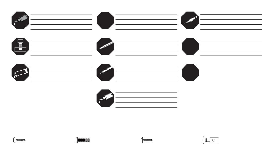
ASSEMBLY SYMBOL GUIDE•MONTAGE SYMBOLE•GUIDE DES SYMBOLES POUR ASSEMBLAGE•GUIDA AI SIMBOLI DI ASSEMBLAGGIO
Use medium CA
Mittelfl üssigen Sekundenkleber verwenden Utilisez de la colle cyanoacrylate moyenne
Usare colla ciano acrilica media
Attach temporarily
Vorübergehend anbringen
Attachez temporairement
Attaccare temporaneamente
Apply threadlock Schraubensicherungslack verwenden Utilisez du frein fi let
Applicare fuido threadlock
|
Repeat multiple times (as indicated) |
x2 |
Vorgang wiederholen (wie angezeigt) |
Répétez comme indiqué |
Ripetere piu’ volte (come indicato)
Use a pencil
Verwenden Sie einen Bleistift
Utilisez un crayon à papier
Usare una matita
Use a felt-tipped pen
Verwenden Sie einen Faserstift
Utilisez un feutre fi n effaçable
Usare un pennarello
Use thin CA
Dünnfl üssigen Sekundenkleber verwenden
Utilisez de la colle cyanoacrylate fi ne
Usare colla ciano acrilica fi ne
Use hobby knife with #11 blade
Verwenden Sie ein Hobbymesser mit # 11 Klinge
Utilisez un Couteau: Lame numéro 11
Usare taglierino per hobbistica con lama numero 11
Use 5-minute epoxy
5Verwenden Sie 5 Minuten Epoxy Utilisez de l’époxy 5 minutes
Usare una resina epossidica con indurimento di 5 minuti
LL |
Assemble right and left |
|
|
Links und rechts montieren |
|
RR |
|
Assemblez à droite et à gauche |
|
|
|
Assemblare destra e sinistra |
|
|
|
FASTENERS•VERBINDUNGSELEMENTE•ATTACHES•ELEMENTI DI FISSAGGIO
Self-Tapping Screw |
Machine screw |
Self-Tapping Washer-Head Screw |
Pushrod connector |
Selbstschneidene Schraube |
Maschinenschraube |
Schraube mit Unterlegscheibenkopf |
Gestängeanschluß |
Vis auto-taraudeuse |
Vis métal |
Vis auto-taraudeuse épaulée |
Connecteur de tringlerie |
Vite autofi lettante |
Vite per metallo |
Vite autofi lettante fl angiata |
Nottolino per i comandi |
10

HINGING THE AILERONS AND FLAPS•MONTAGE DER QUERRUDER UND KLAPPEN•
INSTALLATION DES CHARNIÈRES D’AILERONS ET DE VOLETS•METTERE LE CERNIERE AD ALETTONI E FLAP
1
LL
RR
Remove the aileron and fl ap from the wing.
Nehmen Sie das Querruder und die Klappen von der Tragfl äche ab.
Retirez l’aileron et le volet de l’aile.
Staccare dall’ala alettoni e fl ap.
2
LL
RR
Use a pin vise and 1/16-inch (1.5mm) drill bit to drill a hole in the center of each hinge slot. Prepare both the aileron and wing at this time.
Bohren Sie mit einem 1,5mm Handbohrer ein Loch in die Mitte jeden Scharnierschlitzes. Bereiten Sie so beide Querruder und Tragfl ächen vor.
Utilisez un porte-foret muni d’un foret de 1.5mm pour percer un trou au centre de chaque rainure de charnière. Préparez les deux ailes et les deux ailerons lors de cette étape.
Con una punta da 1,5mm forare al centro di ogni fessura per le cerniere, sia sugli alettoni che sull’ala.
3
LL |
x6 |
|
RR |
||
|
Place a T-pin in the center of each hinge. Slide the hinges into position with the T-pin resting against the edge of the control surface.
Setzen Sie eine T-Nadel in die Mitte jedes Scharnieres. Schieben Sie die Ruder / Klappe in Position und achten bitte darauf, dass die Nadeln an der Flächenkante anliegen.
Placez une épingle en “T” au centre de chaque charnière. Glissez les charnières en position en plaquant les épingles contre le bord d’attaque de chaque gouverne.
Mettere uno spillo a T al centro di ogni cerniera. Inserire ogni cerniera nella sua fessura fi no a che lo spillo è contro al bordo della superfi cie mobile.
4
LL
RR
Place the fl ap and aileron in position on the wing. Check the gap between the tip and aileron, between the aileron and fl ap, and at the root of the wing using a straight edge. Adjust the gap so they are all equal.
Richten Sie die Klappe und das Querruder auf der
Tragfl äche aus. Überprüfen den Spalt zwischen Ende und Wurzel von beiden mit einem Rechteck und justieren diese so, dass der Spalt gleich ist.
Placez l’aileron et le volet en position sur l’aile. Contrôlez l’écart entre le saumon et la pointe de l’aileron, l’écart entre l’aileron et le volet et l’alignement du volet par rapport à l’emplanture de l’aile en utilisant une équerre. Ajustez la position des gouvernes de façon à obtenir de chaque côté un écart équivalent.
Posizionare fl ap e alettoni sull’ala. Usando un righello, verifi care il gioco tra alettoni ed estremità alare, fra alettoni e fl ap e radice dell’ala. Regolare in modo che il gioco sia uguale dappertutto.
11
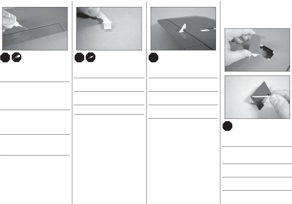
5
LL
RR
Apply thin CA to the top and bottom of each hinge. Once the CA cures, gently pull on the fi xed surface and control surface to make sure the hinges are glued securely. If not, apply additional CA to secure each of the hinges.
Tragen Sie oben und unten an jedem Scharnier eine dünne Linie Sekundenkleber auf. Wenn der Klebstoff ausgehärtet ist, ziehen Sie vorsichtig am Ruder und Ruderblatt um sicherzustellen, dass die Scharniere fest angeklebt sind. Ist dies nicht der Fall, tragen Sie noch etwas Sekundenkleber auf, um die Scharniere zu befestigen.
Appliquez de colle CA fl uide sur le dessus et le dessous de chaque charnière. Une fois le séchage de la colle terminé, tirez doucement sur la gouverne pour contrôler le collage des charnières. Si le collage n’est pas
suffi sant, appliquez de nouveau de la colle CA sur chaque charnière.
Mettere della colla CA liquida sopra e sotto ad ogni cerniera. Quando la colla è asciutta, tirare delicatamente le superfi ci mobili per accertarsi che l’incollaggio sia sicuro. In caso contrario aggiungere altra colla sulle cerniere.
6
LL
RR
Trim the portion of the control horn that fi ts into the aileron so it does not protrude through the top of the aileron.
Schneiden Sie den Steg des Ruderhorn passend, so dass er in den Schlitz in dem Querruder paßt und sich nicht durch die Oberseite drückt.
Coupez la partie du guignol qui entre dans l’aileron de façon qu’elle ne traverse pas la surface supérieure de l’aileron.
Tagliare parzialmente la parte di squadretta che entra nell’alettone in modo che non esca dalla parte superiore.
7
LL
RR
Check the fi t of the control horn in the slot on the aileron. Once fi t, remove the horn and use thick CA to glue the control horn tab and base in the aileron.
Überprüfen Sie die Passung des Ruderhorns im Querruderschlitz. Ist diese korrekt kleben Sie das Horn mit dickfl üssigen Sekundenkleber ein.
Contrôlez l’ajustement du guignol dans la fente de l’aileron. Une fois que l’ajustement est effectué, retirez le guignol et collez son embase sur la surface de l’aileron.
Verifi care l’adattamento della squadretta nell’alettone. Togliere la squadretta e mettere della colla CA per
fi ssarla.
AILERON SERVO INSTALLATION• EINBAU DES QUERRUDERSERVO• INSTALLATION DES SERVOS D’AILERONS•
INSTALLAZIONE SERVO ALETTONE
1
LL
RR
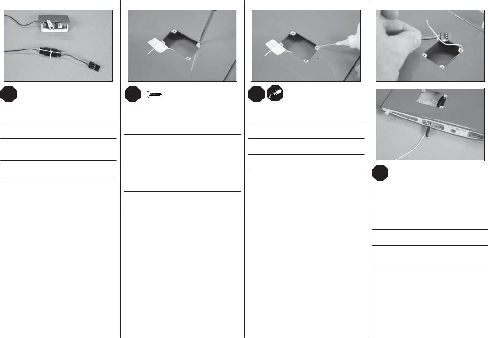
Remove the cover for the aileron servo from the wing. Use a toothpick or T-pin to puncture the covering on the cover for the mounting screws.
Nehmen Sie die Abdeckung vom Querruderservo von der Tragfl äche. Punktieren Sie mit einem
Zahnstocher die Bespannung auf der Tragfl äche für die Montageschrauben.
Retirez de l’aile le couvercle du servo d’aileron. Utilisez un cure dent ou une épingle pour percer l’entoilage au niveau des passages des vis de fi xation.
Togliere dall’ala il coperchio dell’alloggiamento per il servo, con uno stuzzicadenti o uno spillo a T, forare il rivestimento per le viti di fi ssaggio.
12
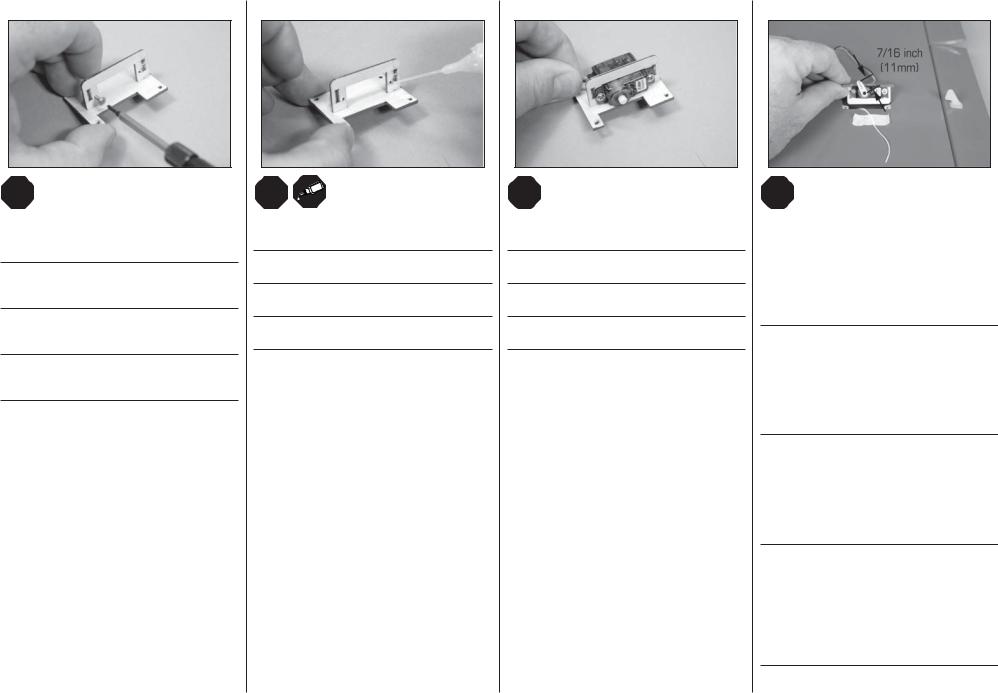
2
LL
RR
Thread a servo mounting screw into each of the holes in the aileron servo mounting holes. Remove the screws before proceeding.
Drehen Sie in jedes Servobefestigungsloch einmal eine Servoschraube. Entfernen Sie die Schrauben bevor Sie weiter machen.
Visser une vis de montage de servo dans chacun des trous de montage du servo d’aileron. Redévisser les vis avant de poursuivre.
Avvitare una vite per il montaggio dei servi in ognuno dei fori del supporto servi alettoni. Svitare le viti prima di procedere.
3
LL
RR
Apply a small amount of thin CA to harden the threads made in the previous step.
Geben Sie einen kleinen Tropfen dünnfl üssigen Sekundenkleber in die Gewindelöcher um diese zu härten.
Appliquer une petite quantité de colle cyano fi ne pour durcir les fi letages faits lors de l’étape précédente.
Mettere una piccola quantità di colla CA nei fori, per indurire il fi letto fatto nel passaggio precedente.
4
LL
RR
Secure the servo to the cover using the screws provided with the servo.
Befestigen Sie das Servo mit den mitgelieferten Schrauben an der Abdeckung.
Fixer le servo à la trappe à l’aide des vis fournies avec le servo.
Fissare il servo alla copertura usando le viti fornite insieme al servo stesso.
5
LL
RR
Center the aileron servo using the radio system. With the servo centered, attach the servo arm so it is two splines from perpendicular toward the leading edge of the wing. Remove any remaining arms from the horn.
The aileron linkage will connect to the hole that is 7/16 inch (11mm) from the center of the servo horn. Shorten the servo arm beyond the attachment point so it does not interfere with the operation of the aileron servo.
Zentrieren Sie das Querruderservo mit der Fernsteuerung und setzen den Servoarm zwei Zacken in Richtung Tragfl ächenvorderkante auf das Servo. Entfernen Sie alle übrigen Arme des Servos. Die
Querruderanlekung wird in das Loch gesteckt das 11mm von der Mitte des Servhorn entfernt ist. Kürzen Sie den Arm hinter dem Anschluss, so dass er den Betrieb nicht stört.
Placez le servo d’aileron au neutre en utilisant votre radio. Placez le bras de servo en le décalant de 2 cannelures vers l’avant de l’aile par rapport à la position verticale. Coupez les bras inutilisés du palonnier. La tringlerie se connectera au trou situé à 11mm du centre du servo. Réduisez l’épaisseur du bras de servo autour du trou de fi xation de façon qu’il n’interfère pas dans le mouvement du servo d’aileron.
Centrare il servo dell’alettone accendendo il radiocomando. Poi inserire la sua squadretta in modo che sia spostata di 2 denti verso il bordo di entrata, rispetto alla posizione perpendicolare. Tagliare gli altri bracci per evitare che interferiscano nei movimenti. La barretta di controllo si collega al foro della squadretta che si trova a 11mm dal centro. Accorciare la squadretta in modo che la parte eccedente non vada a interferire con i movimenti.
13
6
LL
RR
Secure a 3-inch (76mm) extension to the servo lead using string or dental fl oss.
Sichern Sie die 76mm Servokabelverlängerung mit Zahnseide oder einer Schnur.
Sécurisez une rallonge de servo de 76mm au bout du câble de servo d’aileron en utilisant de la fi celle ou du fi l dentaire.
Fissare al connettore del servo una prolunga da 76mm usando dello spago o del fi lo interdentale.
7
LL |
M2 x 10 |
|
|
RR |
x8 |
Thread a screw into each of the holes in the aileron servo cover mounting holes. Remove the screws before proceeding. Prepare the holes for the fl ap servo covers at this time as well.
Drehen Sie eine Servoschraube in jedes der Löcher und wieder heraus. Bereiten Sie die Löcher der
Klappenservoabdeckungen zu diesem Zeitpunkt ebenfalls vor.
Vissez une vis dans chaque trou de fi xation de couvercle de servo d’aileron puis retirez les vis. Effectuez la même opération avec les trous de fi xation des couvercles de servo de volets.
Avvitare una vite in ciascuno dei fori per il fi ssaggio del coperchio, poi toglierla prima di procedere. Fare la stessa cosa anche per i servi dei fl ap.
8
LL
RR
Apply a small amount of thin CA to harden the threads made in the previous step.
Geben Sie einen kleinen Tropfen dünnfl üssigen Sekundenkleber in die Gewindelöcher um diese zu härten.
Appliquer une petite quantité de colle cyano fi ne pour durcir les fi letages faits lors de l’étape précédente.
Mettere una piccola quantità di colla CA nei fori, per indurire il fi letto fatto nel passaggio precedente.
9
LL
RR
Tie the string located inside the wing to the end of the servo lead. Use the string to pull the servo lead through the wing.
Knoten Sie das Ende der Schnur in der Tragfl äche um das Servokabel. Ziehen Sie die Schnur durch die Tragfl äche.
Nouez de la fi celle autour de la prise de servo de la rallonge. Tirez la prise à travers l’aile.
Legare lo spago che si trova all’interno dell’ala al connettore del servo. Usare lo spago per tirare il connettore all’interno dell’ala.
14
10
LL |
M2 x 10 |
|
|
RR |
x8 |
Secure the servo cover to the wing using four M2 x 10 self-tapping screws.
Schrauben Sie die Servoklappe an die Tragfl äche mit den vier M2 x 10 selbstschneidenen Schrauben.
Fixer le couvercle de servo à l'aide de 4 vis autotaraudeuses M2 x 10.
Fissare la copertura del servo all'ala usando quattro viti autofilettanti M2 x 10.
11
x2 

 N
N
x2 |
x2 |
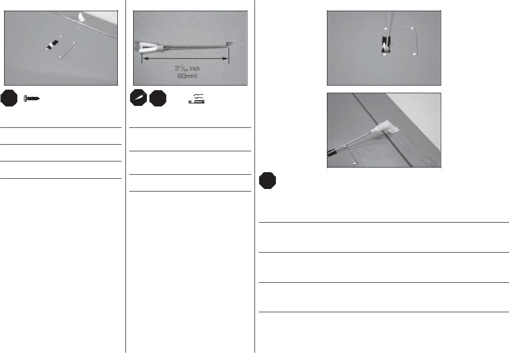
Thread the clevis on a pre-bent M2 x 75 aileron rod. This pushrod has a Z-bend in the end as shown.
Drehen Sie den Gabelkopf auf die vorgebogene M2 x 75 Querruderanlenkung. Diese Anlenkung ist mit einem Z-Ende ausgestattet.
Vissez la chape plastique dans la tringlerie coudée M2x75mm. L’extrémité de cette tringlerie est coudée en “Z”.
Avvitare una forcella sulla barretta M2x75mm che ha una estremità piegata a Z.
12
LL
RR
Insert the Z-bend in the hole that is 7/16 inch (11mm) from the center of the aileron servo horn. Connect the clevis to the center hole of the aileron control horn. With the radio system on and the aileron servo centered, adjust the length of the linkage so the aileron is centered. Once set, slide the tubing over the forks of the clevis to secure the clevis to the control horn.
Setzen Sie das Z-gebogene Ende in das Loch ein das 11mm von der Mitte des Querruderservohorns entfernt ist. Schließen Sie den Gabelkopf in dem mittlerem Loch des Ruderhorns an. Justieren Sie mit eingeschalteter Fernsteuerung und zentriertem Servo das Gestänge so, dass das Querruder zentriert ist. Schieben Sie nach dem Einstellen das Schlauchstück über den Gabelkopf um diesen zu sichern.
Glissez la partie en Z dans le trou du bras de servo situé à 11mm du centre. Connectez la chape au trou central du guignol. Avec votre radio sous tension et le servo au neutre, ajustez la longueur de la tringlerie pour placer la gouverne parfaitement au neutre, une fois que le réglage est effectué, glissez le morceau de durite sur les fourches de la chape afi n de sécuriser la liaison.
Inserire l’estremità piegata a Z nel foro che si trova a 11mm dal centro sulla squadretta del servo. Collegare la forcella al foro centrale sulla squadretta dell’alettone. Con il radiocomando acceso e il servo alettoni centrato, regolare la lunghezza della barretta in modo che l’alettone sia centrato. Fatto questo, far scorrere il tubetto sulla forcella per evitare che si apra in volo.
15
 Loading...