


F-4

F-4 Phantom 32 DF
Assembly Manual
* Pilot figures shown are not included

Notice
All instructions, warranties and other collateral
documents are subject to change at the sole
discretion of Horizon Hobby, Inc. For up-to-date
product literature, visit http://www.horizonhobby.
com and click on the support tab for this product.
Meaning of Special Language
The following terms are used throughout the product
literature to indicate various levels of potential harm
when operating this product:
NOTICE: Procedures, which if not properly followed,
create a possibility of physical property damage
AND a little or no possibility of injury.
CAUTION: Procedures, which if not properly followed,
create the probability of physical property damage
AND a possibility of serious injury.
WARNING: Procedures, which if not properly followed,
create the probability of property damage, collateral
damage, and serious injury OR create a high
probability of superficial injury.
This is a sophisticated hobby product and NOT a
toy. It must be operated with caution and common
sense and requires some basic mechanical
ability. Failure to operate this Product in a safe
and responsible manner could result in injury or
damage to the product or other property. This
product is not intended for use by children without
direct adult supervision. Do not attempt disassembly,
use with incompatible components or augment
product in any way without the approval of Horizon
Hobby, Inc. This manual contains instructions for
safety, operation and maintenance. It is essential to
read and follow all the instructions and warnings
in the manual, prior to assembly, setup or use, in
order to operate correctly and avoid damage or
serious injury.
Warnings
Read and follow all instructions and safety precautions
before use. Improper use can result in fire, serious
injury and damage to property.
Age Recommendation:
For advanced fliers ages 14 and above.
This is not a toy.
COMPONENTS
INTAKE/FAN
Keep loose items that can get entangled in the
fan away from the intake and exhaust, including
loose clothing or other objects such as pencils and
screwdrivers. Especially keep your hands away from
the intake and exhaust, as injury can occur.
BATTERIES
Notes on Lithium Polymer Batteries
When misused, lithium polymer batteries are
significantly more volatile than alkaline or Ni-Cd/
Ni-MH batteries used in RC applications. Always
follow the manufacturer’s instructions when using and
disposing of any batteries. Mishandling of Li-Po batteries
can result in fire causing serious injury and damage.
SMALL PARTS
This kit includes small parts and should not be left
unattended near children as choking and serious injury
could result.
SAFETY PRECAUTIONS
• Checkallcontrolsurfacespriortoeachtakeoff.
• Donotflyyourmodelnearspectators,parking
areas or any other area that could result in injury to
people or damage of property.
WARNING: Read the ENTIRE instruction
manual to become familiar with the features of the
product before operating. Failure to operate the
product correctly can result in damage to the
product, personal property and cause serious injury.
2 E-flite F-4 Phantom 32 DF Assembly Manual
Use only with compatible components. Should any
compatibility questions exist, please refer to the
product instructions, the component instructions or
contact Horizon Hobby, Inc.
FLIGHT
Fly only in open areas to ensure safety. It is
recommended flying be done at AMA (Academy of
Model Aeronautics) approved flying sites. Consult local
laws and ordinances before choosing a location to fly
your aircraft.
• Donotflyduringadverseweatherconditions.
Poor visibility and/or strong winds can cause
disorientation and loss of control of your aircraft.
• Donottakechances.Ifatanytimeduringflightyou
observe any erratic or abnormal operation, land
immediately and do not resume flight until the cause
of the problem has been ascertained and corrected.
Safety can never be taken lightly.
• Donotflynearpowerlines.

Table of Contents
Introduction
Using the Manual
Introduction ........................................................... 3
Important Information Regarding
Warranty Information ..................................... 3
Specifications ......................................................... 3
Using the Manual ................................................... 3
Contents of Kit/Parts Layout .................................... 3
Recommended Radio Equipment ............................. 4
Motor Setup ........................................................... 4
Optional Accessories .............................................. 4
Optional Retracts ................................................... 4
Optional Batteries .................................................. 4
UltraCote® Covering Colors .................................... 4
Hardware/Accessory Sizes ..................................... 4
Required Tools and Adhesives ................................. 4
Wing Tip Installation .............................................. 5
Hinging the Ailerons and Flaps ............................... 6
Aileron and Flap Servo Installation .......................... 7
Control Horn Installation ....................................... 10
Flap and Aileron Linkage Installation ..................... 11
Wing Spar Installation .......................................... 13
Main Landing Gear Installation ............................. 15
Optional Main Landing Gear Doors ...................... 18
Rudder and Elevator Servo Installation ................... 21
Rudder Installation ............................................... 22
Elevator Installation .............................................. 24
Fan Installation..................................................... 26
Nose Gear Installation .......................................... 28
Receiver and Speed Control Installation ................. 32
Motor Battery Installation ...................................... 33
Canopy Assembly ................................................ 34
Decal Placement ................................................... 35
Center of Gravity ................................................. 36
Control Throws..................................................... 37
Preflight ............................................................... 37
Range Test Your Radio .......................................... 38
Flying Your Model ................................................ 38
Daily Flight Checks ............................................... 39
Limited Warranty ................................................. 39
Warranty Services ................................................ 40
Compliance Information for the European Union .... 41
Academy of Model Aeronautics
National Model Aircraft Safety Code ............ 41
E-flite takes scale ARF ducted fan performance and
engineering to new heights with the F-4 Phantom
32 DF. Designed around the E-flite® Delta-V® 32
80mm fan unit and 2150Kv DF32 brushless motor, its
bifurcated intake and exhaust, which are engineered
for best performance, allow this potent combo to
produce large amounts of thrust when powered with
an E-flite 6S 5000mAh 30C Li-Po pack. And it does
so without resorting to drag-inducing cheater holes.
The result is a sport EDF with exhilarating speed that
will give even experienced jet jockeys goose bumps.
The Platinum Series E-flite
32 also boasts a level of fit and finish that is every bit
as impressive as its performance. Its sleek fiberglass
fuselage comes pre-painted and integrates the vertical
stabilizer. The fully-sheeted wings are mounted with
carbon blade spars and the full flying stabilator is
preassembled from the factory to ensure accuracy.
And it’s covered with genuine UltraCote® covering for
the best look and finish. Just add the optional E-flite
electric retracts (sold separately), and you’ve got a
scale jet that truly stands out from the crowd.
®
ducted fan F-4 Phantom DF
Important Information
Regarding Warranty Information
Please read our Warranty and Liability Limitations in
the back of this manual before building this product.
If you as the Purchaser or user are not prepared
to accept the liability associated with the use of
this Product, you are advised to return this Product
immediately in new and unused condition to the place
of purchase.
Specifications
Wingspan: 34.8 in (885mm)
Wing Area: 406 sq in (26.2 sq dm)
Length: 47.2 in (1200mm)
Weight w/o Battery: 5.15–5.45 lb (2.35–2.50 kg)
Weight with Battery: 7.05–7.40 lb (3.20–3.35 kg)
This manual is divided into sections to help make
assembly easier to understand and to provide breaks
between each major section. In addition, check boxes
have been placed next to each step to keep track
of its completion. Steps with a single circle () are
performed once, while steps with two or more circles
() indicate the step will require repeating, such as
for a right or left wing panel, two servos, etc.
Remember to take your time and follow the directions.
Contents of Kit/Parts Layout
Replacement Parts
EFL812501 Fuselage with Hatches
EFL812502 Main Wing Left
EFL812503 Main Wing Right
EFL812504 Horizontal Stabilizer Assembly
EFL812505 Canopy and Engine Hatches
EFL812506 Plastic Accessories
EFL812507 Rudder
EFL812508 Hardware
EFL812509 Pushrods
EFL812510 Decal Sheet
EFL812511 Landing Gear Struts
EFL812512 Tail Cone
EFL812513 Fixed Nose Gear
EFL812514 Foam Main Wheels, 48mm dia
EFL812515 Foam Nose Wheels, 33mm dia
3E-flite F-4 Phantom 32 DF Assembly Manual

Recommended Radio Equipment
Motor Setup
Required Tools and Adhesives
You will need a minimum 5-channel transmitter,
receiver and seven servos.
Complete Radio System
SPM8800 DX8 DSM2™ 8CH system
8-channel receiver installation:
SPMAR8000 AR8000 DSMX 8-Channel Full-
Range Receiver
JSP20030 MC35 Servo (6)
JRPSDS3421 DS3421 Premium Digital Servo,
elevator
SPMA3058 Y-harness
SPMA3052 9-inch (228mm) servo extension
The extensions listed for the 8-channel
operation (separate ailerons and nose gear)
will require the use of mixing at the transmitter.
6-channel receiver installation:
SPMAR6210 AR6210 DSMX 6-Channel Full-
Range Receiver
JSP20030 MC35 Servo (6)
JRPSDS3421 DS3421 Premium Digital Servo,
elevator
SPMA3058 Y-harness (3)
SPMA3052 9-inch (228mm) servo extension
lightweight
The extensions listed for the 6-channel
operation will require surfaces (flaps, ailerons
and steering-to-rudder) using a Y-harness.
EFLM3032DFA DF32 Brushless Motor, 2150Kv
EFLDF32 Delta-V® 32 80mm EDF
EFLA1080B 80-Amp Pro SB
Brushless ESC v2
EFLB50006S30 5000mAh 6S 22.2V 30C Li-Po,
10AWG EC5
Optional Accessories
EFLC3025 Celectra™ 80W AC/DC Multi-
Chemistry Battery Charger
EFLA110 Power Meter
EFLAEC512 EC5™ Device Charge Lead with
6-inch Wire and Jacks, 12AWG
PKZ7003 Pilot (2)
Optional Retracts
EFLG230 15–25 Tricycle Electric Retracts
SPMA3000 3-inch (76mm) Servo
Extension (2)
SPMA3004 18-inch (457mm) servo
extension
Optional Batteries
EFLB50006S50 5000mAh 6S 22.2V 50C Li-Po,
10AWG EC5
THP50006SPP65 5000mAh 6-Cell/6S 22.2V
G64 Pro Power 65C Li-Po
UltraCote® Covering Colors
Light Gray HANU882
True Red HANU866
Silver HANU881
White HANU870
Tools & Equipment
Balancing stand Ball driver: 9/64-inch
Flexible tape Clear tape
Drill Coarse grit sandpaper
Epoxy brush Felt-tipped pen
Hobby scissors Low-tack tape
Mixing cup Mixing stick
Needle-nose pliers Paper towels
Pencil Petroleum jelly
Pin vise Razor saw
Rotary tool Rubbing alcohol
Ruler Sanding block
Sanding drum Scissors
Side cutter String
Tie-wraps Toothpick
Trim seal tool Two-sided tape
Flat file
Drill bit: 1/16-inch (1.5mm), 5/64-inch (2mm)
Hex wrench: 1.5mm, 2.5mm
Hobby knife with #11 blade
Medium grit sandpaper
Phillips screwdriver: #0, #1
Adhesives
5-minute epoxy PAAPT38
15-minute epoxy MEUEPX15MIN
CA accelerator PAAPT715
Canopy glue PAAPT56
Thin CA PAAPT08
Threadlock PAAPT42
Silicone adhesive DEVS250
Hardware/Accessory Sizes
Main wheel diameter 17/8-inch (48mm)
Nose wheel diameter 15/16-inch (33mm)
Wing bolt 8-32 x 1/4-inch
4 E-flite F-4 Phantom 32 DF Assembly Manual
During the course of building your model, we
suggest you use a soft base for the building surface.
Such things as a foam stand, large piece of
bedding foam or a thick bath towel will work well
and help protect the model from damage during
assembly. This is not shown in the instructions
to provide the greatest detail in the photos.
When referencing directions (up, down, left,
right top and bottom), these directions are in
relationship to the pilot sitting in the cockpit
of the aircraft unless noted otherwise.
Before starting the assembly of your model, we
recommend preparing your radio system for
installation. This includes charging the transmitter and
receiver batteries, as well as centering the trims and
sticks on your transmitter. If using a computer radio,
make sure to reset a model memory and name it for
this particular model. We also recommend binding
the transmitter and receiver at this time following
the instructions provided with your radio system.
Wing Tip Installation
Required Parts
Main wing panel (right and left)
Wing tip (right and left)
3mm x 40mm hardwood dowel (4)
Required Tools and Adhesives
Felt-tipped pen 5-minute epoxy
Mixing stick Mixing cup
Low-tack tape Rubbing alcohol
Paper towels Hobby knife with #11 blade
1. Insert the two 3mm x 40mm hardwood dowels
into the wing tip panel.
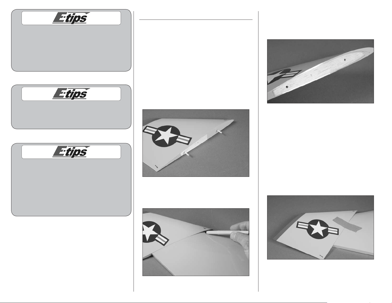
2. Fit the tip panel to the main panel. Use a felt-
tipped pen to trace the outline of the main wing
panel on the tip panel.
3. Remove the tip panel and dowels. Use a hobby
knife and #11 blade to remove the covering 1/32inch (1mm) inside the line drawn. Use a paper
towel and rubbing alcohol to remove the pen lines.
4. Use 5-minute epoxy to glue the two 3mm x
40mm hardwood dowels into the wing tip panel.
Use a paper towel and rubbing alcohol to remove
any excess epoxy. Allow the epoxy to fully cure
before proceeding.
5. Apply a thin coat of 5-minute epoxy to the
exposed wood of the main wing panel and the
wing tip panel, as well as to the wood dowels.
Fit them together and use low-tack tape to hold
them together until the epoxy fully cures. Remove
any excess epoxy using a paper towel and
rubbing alcohol.
We highly recommend re-binding the radio
system once all the control throws are set. This will
keep the servos from moving to their endpoints
until the transmitter and receiver connect.
6. Repeat steps 1 through 5 to install the remaining
wing tip panel to the main wing panel.
5E-flite F-4 Phantom 32 DF Assembly Manual
Hinging the Ailerons and Flaps
Required Parts
Wing panel (left and right)
Aileron (left and right)
Flap (left and right) CA hinge (8)
Required Tools and Adhesives
Thin CA T-pins
Pin vise Drill bit: 1/16-inch (1.5mm)
Please follow the procedure for hinging
the ailerons and flaps as described in this
manual. Failure to correctly hinge these surfaces
could result in the surface becoming loose in
flight, resulting in the loss of your aircraft.
2. Slide the hinges into the aileron and flap. Insert
the hinges so the holes in the hinge are at the
hinge line. Insert a T-pin through one of the holes to
keep the hinge centered while the aileron and flap
are installed on the wing panel.
1. Use a pin vise and 1/16-inch (1.5mm) drill bit
to drill a hole in the center of each hinge slot in the
ailerons, flaps and wing panels. This will provide
a tunnel for the CA to wick into, making the bond
between the hinge and wood stronger.
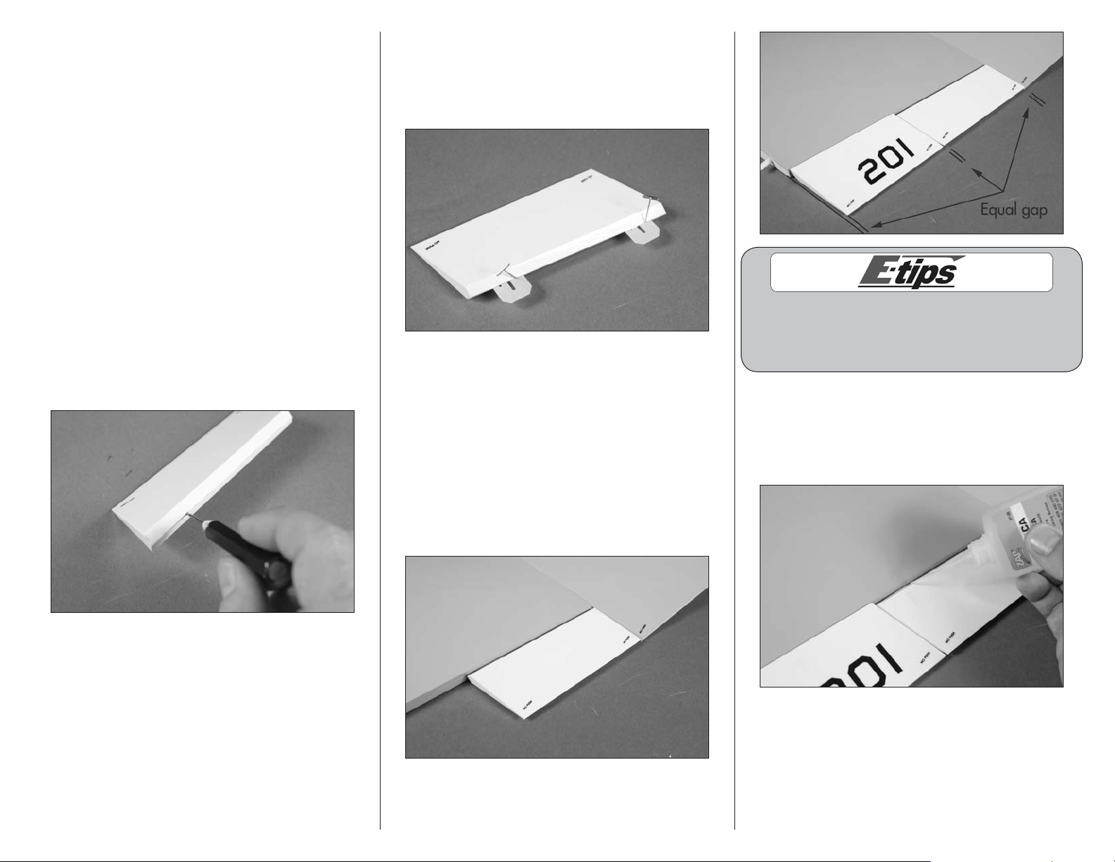
3. Slide the hinges in the aileron into the slots on
the wing. Note the orientation of the ailerons and
flaps. They will only fit correctly one way with all
decals showing on the top. Leave a small gap
at the wing tip. Installl the flap making sure the
aileron and flap can move without interference.
Also make sure the flap is set in an equal distance
from a line projected from the root of the wing to
prevent it from rubbing against the fuselage. The
gap between each surface, and the line projected
from the wing root, should be equal.
When gluing the hinges, do not use a CA
accelerator. The CA must be allowed time to
soak into the hinges to provide the best bond
between the hinge and surrounding wood.
4. Remove the T-pins from the hinges. Make sure
the aileron and flap are tight against the wing.
Wick thin CA into each hinge, both top and
bottom, until the hinge is saturated with CA. Allow
the CA to fully cure before proceeding.
6 E-flite F-4 Phantom 32 DF Assembly Manual
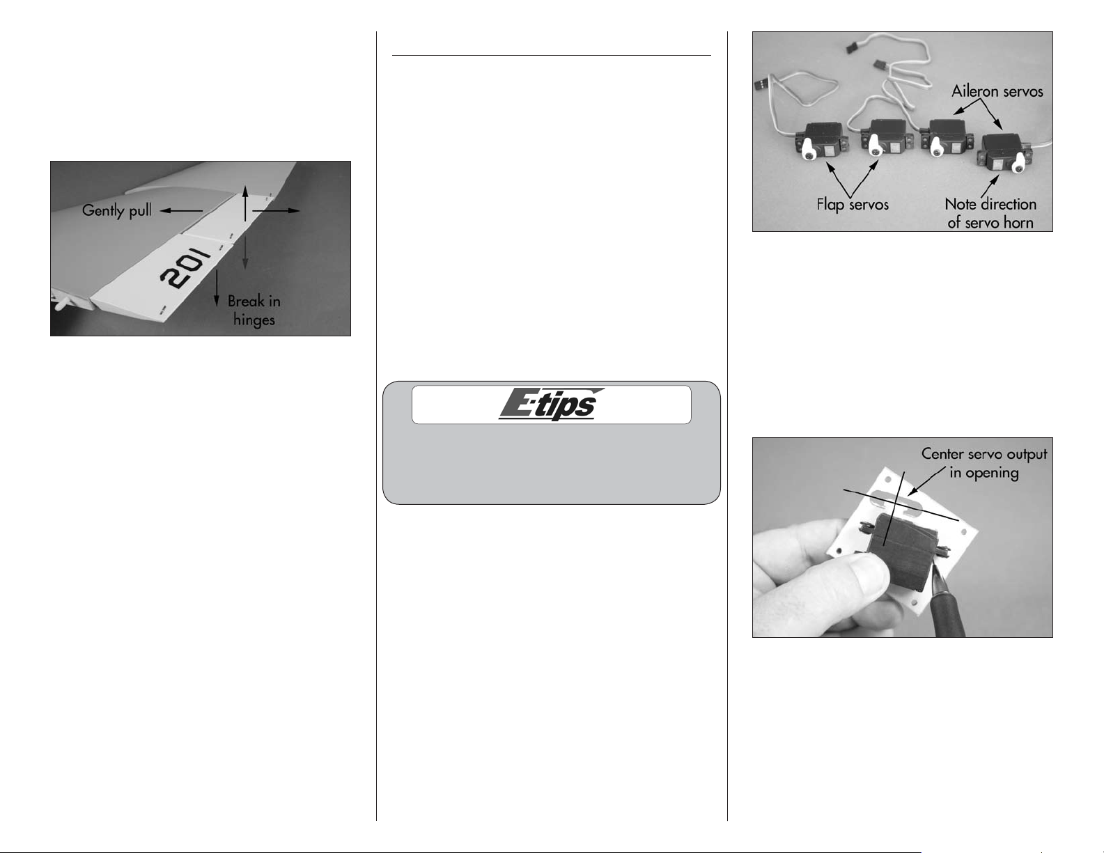
5. Once the CA has fully cured, gently pull on
the wing and aileron (and flap) to make sure the
hinges are glued securely. If not, reapply thin CA
to any hinges that are not secure. Flex the aileron
and flap through their range of motion a number
of times to break in the hinges. This will reduce the
initial load on the servo for your first flights.
6. Repeat Steps 1 through 5 to install the remaining
aileron and flap hinges.
Aileron and Flap Servo Installation
Required Parts
Wing panel (right and left)
Transmitter Receiver
Receiver battery
Servo with hardware (4)
Hardwood block, 15mm x 13mm x 6mm (8)
2mm x 8mm self-tapping screw (16)
Required Tools and Adhesives
Phillips screwdriver: #1
Hobby knife with #11 blade
Pencil Razor saw
Thin CA 5-minute epoxy
Mixing cup Mixing stick
Drill Drill bit: 5/64-inch (2mm)
Side cutter Pin vise
Felt-tipped pen Medium grit sandpaper
When centering the flap servo, begin by setting
the throws at the transmitter to 0% for both the
up and down flap positions. This should be done
for both 2- and 3-position flap switches.
2. Use a felt-tipped pen to mark the flap and
aileron servo covers so they can be returned to
their correct locations, then remove the covers from
the wing. Set the flap cover aside. Use a pencil
to mark the centerlines for the servo output on the
cover. Position the servo on the cover so the center
of the servo horn is centered in the opening using
the lines drawn on the cover. Use a pencil to mark
the locations for the servo mounting blocks on the
servo cover.
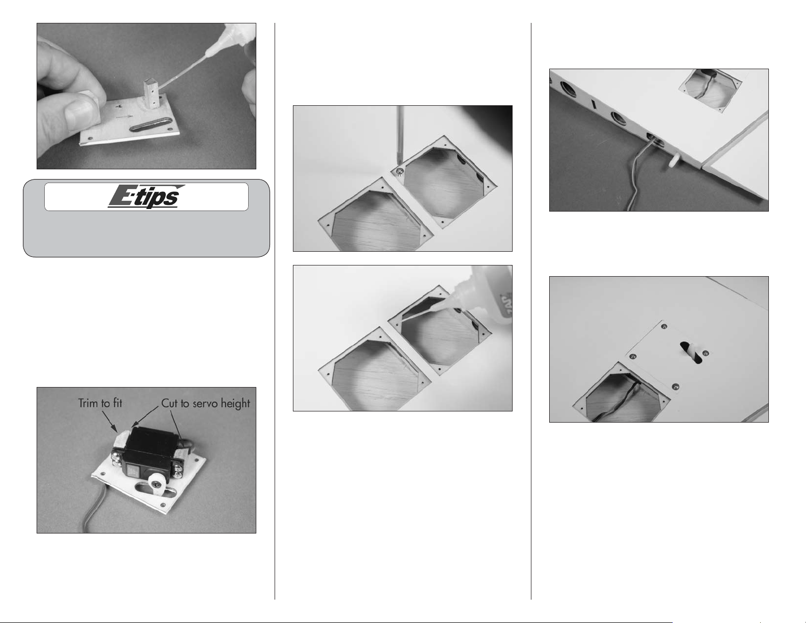
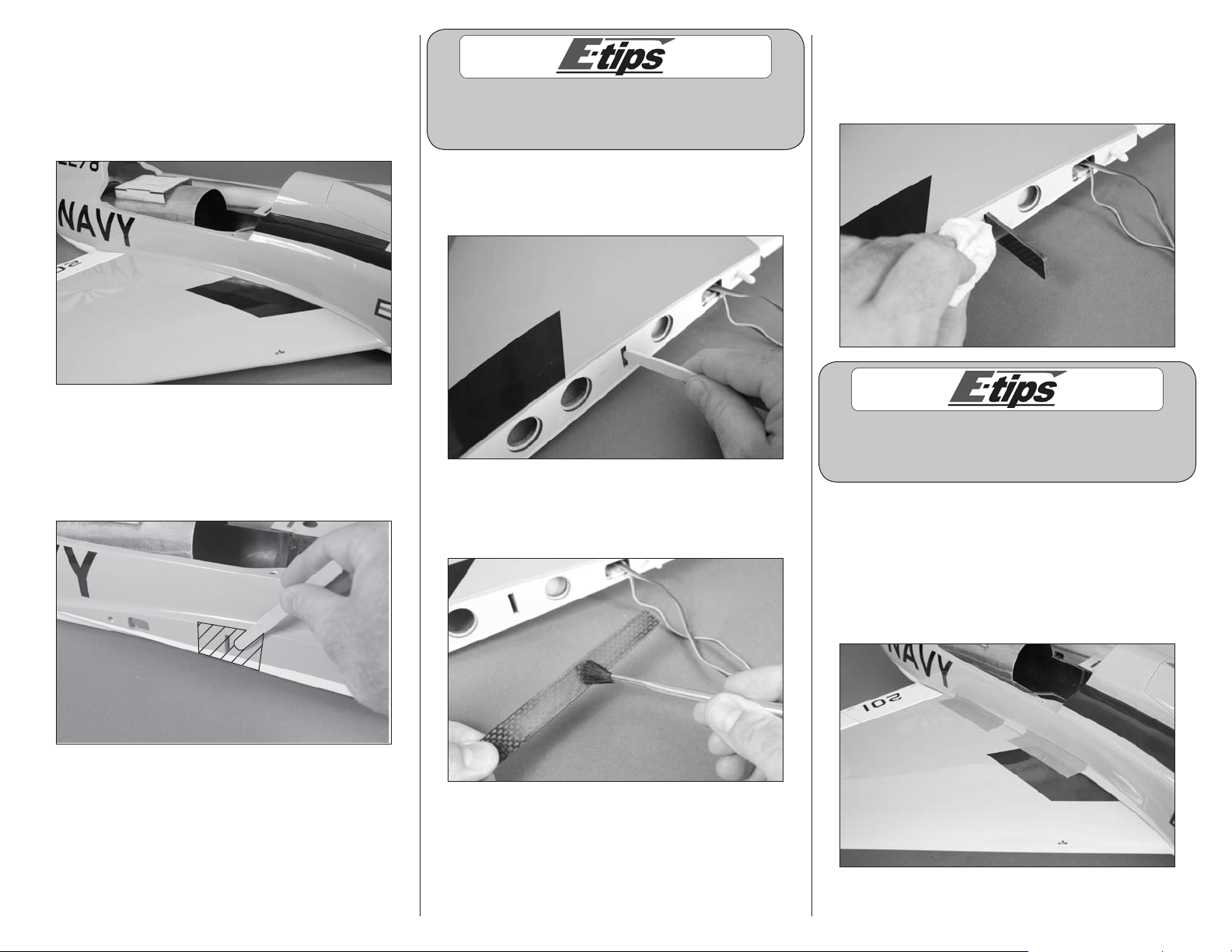
1. Prepare the aileron and flap servos by installing
the rubber grommets and brass eyelets as shown in
the radio or servo instructions. Use the shorter side
of a JR standard horn for the two aileron servos
and the longer side for the flap servos. Center the
aileron and flap servos using the radio system. Use
side cutters to remove any arms from the horn that
may interfere with the operation of the servo. Note
that one servo is set in the opposite orientation as
shown in the photo in the following column.
7E-flite F-4 Phantom 32 DF Assembly Manual
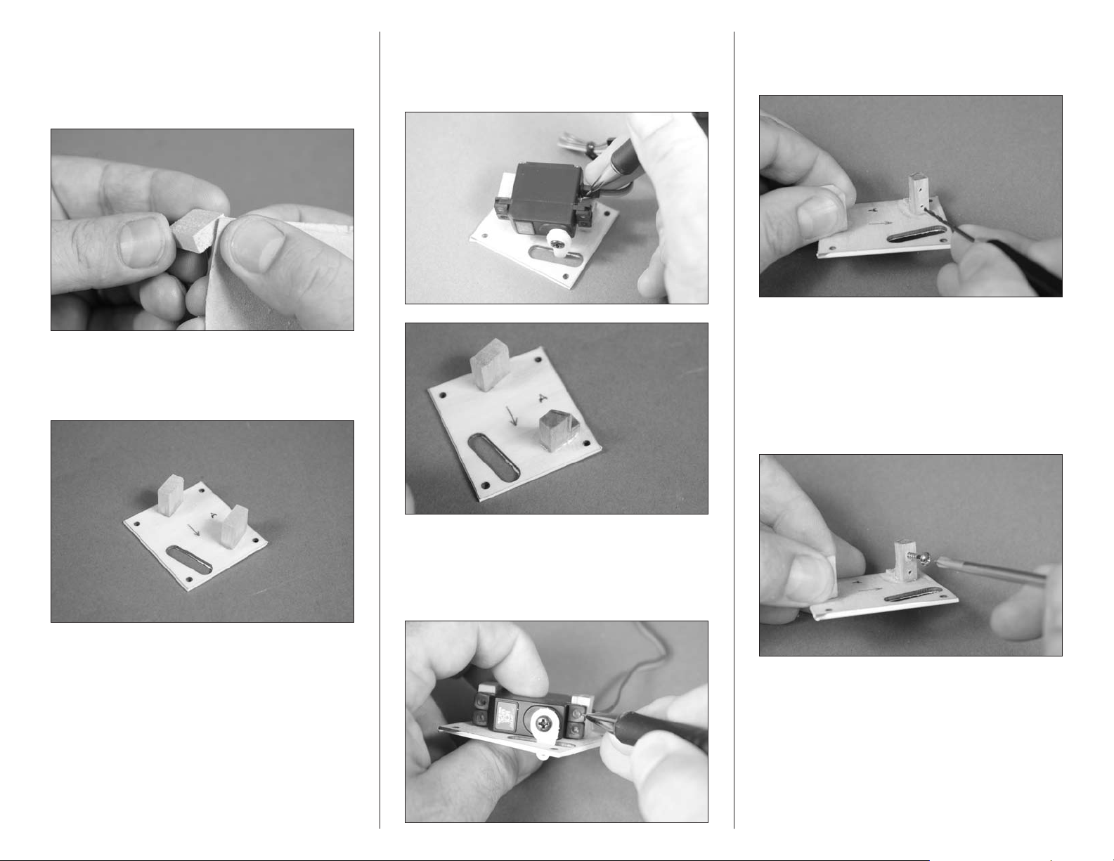
3. Sand the 6mm x 13mm end of the four
hardwood blocks using medium grit sandpaper to
provide a surface for the glue to adhere to. This
will be the end glued to the plate in the following
step.
4. Use 5-minute epoxy to glue the blocks to the
cover in alignment with the marks you made. Allow
the epoxy to fully cure before proceeding.
5. Position the servo on the blocks. Use a
pencil to mark the block for the servo lead. Use a
razor saw to trim the block to provide clearance for
the servo lead.
7. Use a drill and 5/64-inch (2mm) drill bit to
drill the holes for the mounting screws. Use care not
to enlarge the holes any larger than the drill bit.
8. Use a #1 Phillips screwdriver to thread
a servo mounting screw into each of the holes.
Remove the screw then apply 2–3 drops of thin
CA in each hole and saturate the front and rear of
the block to harden the hardwood block. This will
help keep the blocks from splitting when the servo
mounting screws are installed.
6. Position the servo between the two blocks.
With the servo resting against the servo cover, use
a pencil to mark the locations for the four servo
mounting screws on the blocks.
8 E-flite F-4 Phantom 32 DF Assembly Manual
Do not use a CA accelerator. Using an accelerator
will not allow the CA to soak into the fibers of
the wood, hardening the hardwood block.
9. Sand the top of the blocks so they are flush
with the top of the servo. Also trim or sand the
edge of the block so that it does not interfere with
the mounting rim of the wing hole. The blocks may
be a very close fit, and may just hit the mounting
rim on the cover. This is dependant on the exact
location of the servo. Use the screws provided with
the servo and a #1 Phillips screwdriver to attach
the servo to the mounting blocks.
10. Use a #1 Phillips screwdriver to thread a
2mm x 8mm self-tapping screw into each of the
servo cover mounting holes. This will cut threads
in the surrounding wood. Remove the screw then
apply 2–3 drops of thin CA in each hole to harden
the wood.
11. Tie the end of the string around the end of the
aileron servo lead. Use the string to pull the leads
through the wing and out at the root rib as shown.
12. Use four 2mm x 8mm self-tapping screws
and a #1 Phillips screwdriver to secure the aileron
servo cover to the wing.
9E-flite F-4 Phantom 32 DF Assembly Manual
13. Pass the flap servo lead through the same
hole in the wing root as the aileron servo. Use
four 2mm x 8mm self-tapping screws and a #1
Phillips screwdriver to secure the flap servo cover
to the wing.
14. Repeat steps 2 through 13 for the remaining
wing panel.
Control Horn Installation
Required Parts
Wing panel (right and left)
Fiberglass control horn (4)
Required Tools and Adhesives
Felt-tipped pen 5-minute epoxy
Mixing stick Mixing cup
Low-tack tape Coarse grit sandpaper
Hobby knife with #11 blade
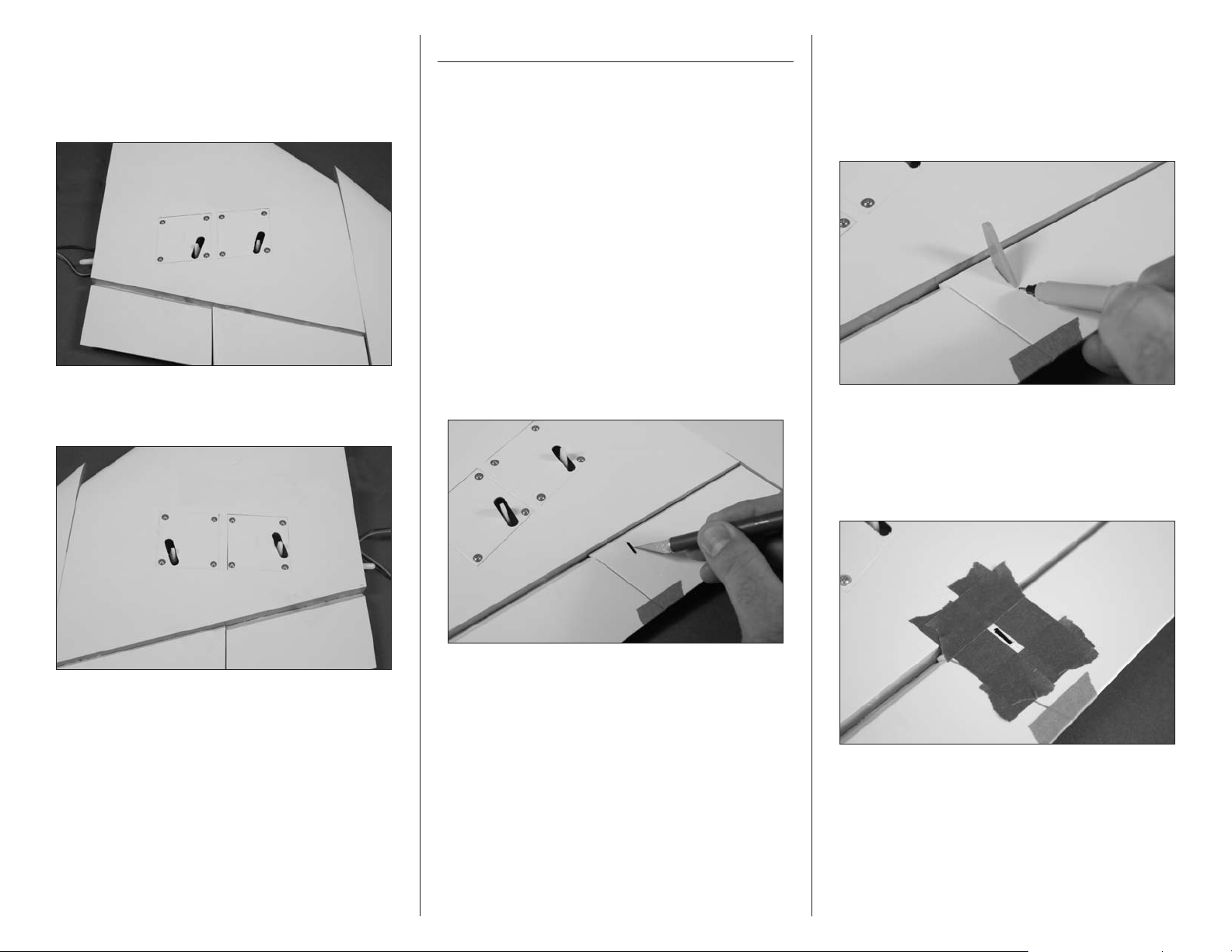
1. Use low-tack tape to tape the aileron at the tip
and tape the flap to the aileron so they don’t move
during the control horn installation.
1. Use a hobby knife and #11 blade to
remove the covering from the slot for the
aileron control horn.
2. Check the fit of the fiberglass control horn
in the slot in the aileron. The hole in the control
horn will align with the hinge line. The horn
should fit flush in the hole. Use a felt-tipped pen to
mark the front and rear edge of the control horn
on the aileron.
3. Apply low-tack tape around the opening
for the aileron control horn. Position the tape so
it is 1/32-inch (1mm) away from the sides of
the hole, as well as from the marks made in the
previous step.
10 E-flite F-4 Phantom 32 DF Assembly Manual
4. Use coarse grit sandpaper to lightly sand
the control horns where they fit into the openings in
the flap and aileron.
7. After around 3 minutes, before the epoxy
cures, carefully remove the tape from around the
control horns. Pull the tape away from the horn,
being careful not to disturb the position of the
control horn. This will allow the epoxy to flow out
slightly, leaving a fillet between the control horn
and control surface.
Flap and Aileron Linkage Installation
Required Parts
Wing panel (right and left)
Transmitter Receiver
Receiver battery Silicone tubing
Metal clevis (8) 2mm nut (6)
Threaded rod, 2mm x 25mm (2)
Threaded rod, 2mm x 40mm (2)
Required Tools and Adhesives
Ruler Threadlock
Needle-nose pliers
5. Repeat Steps 1 through 4 to prepare the
remaining aileron and flap control horns.
6. Use 5-minute epoxy to glue the control horn
into the holes for the aileron. Use a square to make
sure the control horn is perpendicular to the control
surface. Double-check the hole in the control horn
to ensure it is directly over the hinge line.
8. Repeat Steps 6 and 7 to install the remaining
aileron and flap control horn.
Always use threadlock on metal-to-metal fasteners
to prevent them from vibrating loose.
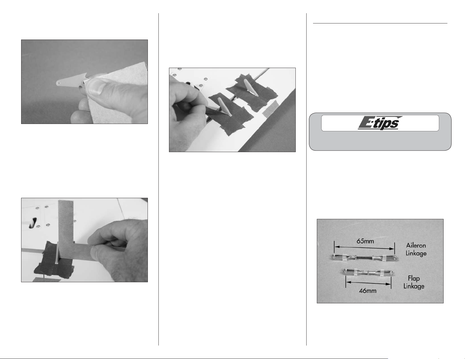
1. Use a hobby knife to cut four 1/4-inch (6mm)
pieces of silicone tubing. Assemble the aileron
linkage using the silicone tubing, two 2mm nuts,
two metal clevises, and a 2mm x 25mm threaded
rod. Assemble the flap linkage using the silicone
tubing, one 2mm nut, two metal clevises, and a
2mm x 25mm threaded rod. Use the length in the
photo as a starting point for the length of the rod.
11E-flite F-4 Phantom 32 DF Assembly Manual
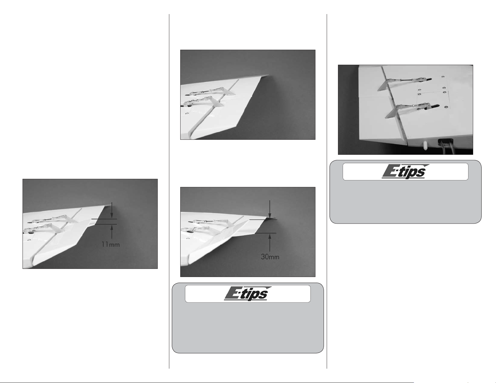
2. Connect the aileron linkage to the hole in the
servo horn 7/16-inch (11mm) from the center of
the servo arm, and connect the flap linkage to the
hole in the servo horn 1/2-inch (13mm) from the
center of the arm.
3. Remove the tape holding the flap and aileron in
position. Connect one clevis of the longer pushrod
to the outer hole of the aileron servo horn. The
remaining clevis connects to the aileron control
horn. Adjust the length of the linkage so the aileron
is centered when the servo is centered. Connect
one clevis of the shorter pushrod to the outer hole
of the flap servo arm and the other end to the
flap control horn. Adjust the length of the flap
linkage so when the flap servo is centered, the
flap is positioned as shown. Once the length of
the linkages has been adjusted, slide the tubing
over the forks of the clevises to keep them from
accidentally opening in flight. Use needle nose
pliers to tighten the nuts against the metal clevises.
4. Set the switch at the transmitter to the UP flap
position. Adjust the flap system values of the
transmitter for the up position until the flap is aligned
with the aileron. This will be the UP flap position.
5. Set the switch at the transmitter to the DOWN
flap position. Adjust the ATV at the transmitter for
the down position until the flap is 30mm below the
aileron. This will be the DOWN flap position.
6. Repeat steps 2 through 5 to prepare and install
the remaining flap and aileron linkages. Before
connecting the flap linkage, set the flap switch to
the UP flap position. Connect the linkage to the flap
servo and adjust its length until the flap is aligned
with the aileron. This will be the UP flap position.
You may have to fine-tune both flap linkages up
or down so they align at all three positions: up,
middle, and down. It is very important to use servo
arms positioned at the same angle on the splines of
the servo so the travel will match in all positions.
Because there can be minor differences in control
horn and servo positions, do not connect the
linkage as described in steps 2 to the opposite
flap until you have checked the throws. Doing so
may cause the servo to bind in the UP position,
which could cause damage to the flap servo.
12 E-flite F-4 Phantom 32 DF Assembly Manual

Wing Spar Installation
Required Parts
Fuselage Carbon wing spar (2)
8-32 x 1/4-inch socket head screw (4)
Wing panel assembly (right and left)
Required Tools and Adhesives
Low-tack tape
15-minute epoxy Mixing cup
Paper towels Mixing stick
Epoxy brush Rubbing alcohol
Ruler Medium grit sandpaper
Petroleum jelly Felt-tipped pen
Ball driver: 9/64-inch
1. Remove the radio cover and canopy from the
fuselage by lifting them up from the base, rather
than from the sides, as the magnets are strong to
hold them down during high-speed maneuvers. The
radio cover is held in place with magnets at the
front and a pin in the rear. Set the cover aside so it
doesn’t get damaged.
2. Use a 9/64-inch ball driver to start the four
8-32 x 1/4-inch socket head bolts in the aluminum
wing sockets inside the fuselage. Only thread the
screws in a few turns at this time. Use care not to
cross-thread the screws and damage the threads in
the aluminum sockets.
3. Locate the carbon wing spar. The spar is
symmetrical and has no top or bottom. Slide the
carbon wing spar in the spar pocket of the wing,
narrow end first. The spar will slide in easily, so
don’t force it in any further than it will slide. Use a
felt-tipped pen to mark the spar at the wing root.
4. Remove the spar from the spar pocket. Use
medium grit sandpaper to lightly sand the spar
where it fits into the wing. Sand both the front and
back of the spar.
5. Slide the spar into the spar pocket in the fuselage.
It will easily slide into the pocket up to the line made
in step 3. If not, the screws installed in step 2 may
be in the way and require loosening.
13E-flite F-4 Phantom 32 DF Assembly Manual
6. Check the fit of the wing on the fuselage. It must
rest tightly against the fuselage. If the spar fits into
the wing and fuselage spar pockets without any
problems, the fit should be perfect. Make sure to
guide the leads for the aileron and flap into the
fuselage so they don’t interfere with the fit.
Before mixing any epoxy, make sure to read through
and understand the following steps. It is important
to perform these steps before the epoxy fully cures.
8. Mix 1/2 ounce (15mL) of 15-minute epoxy.
Apply the epoxy to the spar pocket of the wing
using a mixing stick.
10. Slide the spar into the spar pocket of the wing,
making sure it is oriented correctly. Use a paper
towel and rubbing alcohol to remove any excess
epoxy from the wing and spar.
7. Remove the wing and spar from the fuselage.
Apply a thin coat of petroleum jelly to the fuselage
around the wing socket. This will keep you from
accidentally gluing the wing to the fuselage during
the following procedure.
9. Use an epoxy brush to apply epoxy to the front,
back, top and bottom of the spar where it fits into
the wing.
Epoxy will ooze out from the spar pocket of the
wing. If epoxy does not ooze out, not enough
epoxy was used to glue the spar into the wing.
11. Before the epoxy cures, slide the wing into
position against the fuselage. Keep the wing tight
against the fuselage until the epoxy fully cures. You
can use a 9/64-inch ball driver to lightly tighten
the screws to secure the wing joiner in the fuselage,
and low-tack tape to hold the wing in position until
the epoxy has cured.
14 E-flite F-4 Phantom 32 DF Assembly Manual
 Loading...