


|
TABLE OF CONTENTS |
|
Part #3550 and #3551 |
Introduction................................................................................................................................................. |
1 |
Components................................................................................................................................................ |
2 |
Preliminaries ........................................................................................................................................... |
3-5 |
Fuel System ............................................................................................................................................ |
6-9 |
Induction System................................................................................................................................. |
10-12 |
Sensors ............................................................................................................................................... |
13-15 |
O2 Sensor Installation................................................................................................................................ |
15 |
Main System Harness.......................................................................................................................... |
16-20 |
Ignition System................................................................................................................................... |
21-25 |
Other Applications .................................................................................................................................... |
26 |
System Start-Up .................................................................................................................................. |
26-29 |
Electronic Engine Management ................................................................................................................. |
30 |
Pro-Flo Quick Tuning Guide....................................................................................................................... |
31 |
Calibration Module Flowchart.................................................................................................................... |
32 |
Parts and Part Numbers....................................................................................................................... |
33-34 |
Service & Warranty ................................................................................................................................... |
35 |
INTRODUCTION
Thank you for selecting the Edelbrock Pro-Flo Fuel Injection System. This Multi-Point Fuel Injection System has been designed for 454 c.i.d. bigblock Chevrolet engines, and is designed to provide excellent performance, fuel economy, and maintenance-free operation. Installation of the Edelbrock/ Pro-Flo Fuel Injection System involves modifications to the fuel system, ignition system, induction system, and possibly the valve train. Although there are steps that must take place before others, the modifications do not necessarily have to be performed in a particular order. Each modification is described in a separate section in this manual. Please study these instructions carefully before beginning installation of any part of the Pro-Flo system.
Calibration Chips:
Important Notice: The Edelbrock Pro-Flo Fuel Injection System is shipped without the computer chip. The chip is necessary to operate the ECU. If the cam is any brand other than Edelbrock, check with manufacturer for compatibility with EFI. Complete the Chip Information Card and return to Edelbrock. We will send the computer chip within the continental U.S., free of charge via UPS second day air. Orders outside of the continental U.S. will be shipped via the best method at the same costs as continental UPS second day air. If requested, customers may pay for expedited shipping by providing a current Visa or Master Card. The chip installs into the System Computer in minutes. Additional chips are available for a nominal charge if you decide to change your cam. Edelbrock has chips for assorted cam profiles. If you have any questions, do not hesitate to call.
If you have any questions, do not hesitate to call our
EFI Technical Hotline at (800) 416-8628, 7am-5pm PST, Monday-Friday E-mail: EFItech@edelbrock.com
|
1 |
©2005 Edelbrock Corporation |
Rev. 10/05 |
Pro-Flo EFI Installation Instructions |
Brochure No. 63-0115 |
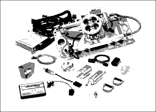
COMPONENTS
Electronic Control Unit/System ECU |
|
Fuel filter |
|
|
Calibration Module |
|
Fuel rail assembly |
|
Distributor conversion kit |
|
Fuel pressure regulator |
|
Ignition amplifier |
|
Fuel injectors |
ECU power relay/Fuel pump relay |
|
Intake manifold |
|
Manifold Absolute Pressure (MAP) Sensor |
Four barrel air valve |
||
Manifold Air Temperature (MAT) Sensor |
Idle Air Control (IAC) solenoid, integrated with air valve |
||
Coolant Temperature Sensor (CTS) |
|
Main system harness |
|
Throttle Position Sensor (TPS), integrated with air valve |
|
Fuel pump harness |
|
|
Oxygen (O2) sensor |
|
Installation package |
High pressure fuel pump
Many Pro-Flo components, including the Manifold Absolute Pressure sensor, fuel pressure regulator, Coolant Temperature sensor, and the fuel filter are standard OEM pieces. In the event that one of these parts needs to be replaced, you are likely to find a replacement at your local parts supplier, in addition to your local Edelbrock dealer or directly from Edelbrock. For a list of part numbers, refer to the PART NUMBERS section at the back of this manual.
|
2 |
©2005 Edelbrock Corporation |
Rev. 10/05 |
Pro-Flo EFI Installation Instructions |
Brochure No. 63-0115 |
TOOLS AND EQUIPMENT |
HARDWARE AND PARTS RECOMMENDED |
||
Use the following checklist for items needed. |
Use the following checklist for items needed. |
||
Box and open end wrenches |
Intake gasket - Edelbrock #7203, OEM, or equivalent |
||
|
Socket set |
Pipe plugs, if needed |
|
|
Distributor wrench |
5/16-inch steel tubing (approximate equal length to fuel pickup |
|
Pliers (channel locks and hose clamp) |
|
line in tank) |
|
Screwdrivers (regular and Phillips) |
|
Edelbrock Gasgacinch #9300 |
|
|
Torque wrench |
|
Loctite 598 OEM High Temperature Silicone Gasket (O2 Sensor |
|
Hammer |
|
Compatible) |
Gasket scraper or putty knife |
|
Radiator coolant |
|
|
Timing light |
Wiring diagram for your vehicle |
|
|
Vacuum gauge |
Teflon tape or liquid Teflon thread sealer |
|
|
Rags |
Manifold bolt kit #8564 |
|
|
Water bucket |
|
Throttle, Cruise Control & Trans. Kick-Down Mounting Bracket |
|
Drill and bits |
|
#8031 (If Necessary see general catalog) |
Hole saw (1 1/4-inch or 1 3/4-inch) |
|
195° Thermostat |
|
|
Tubing wrenches |
Resistor type spark plugs (Use correct heat range for your |
|
|
Tubing cutter |
|
particular application |
|
|
Set of low-resistance spark plug wires with high EMI suppression |
|
|
|
|
(DO NOT use solid core spark plug wires) |
PRELIMINARY CHECKLIST
1.CAREFULLY STUDY AND UNDERSTAND ALL INSTRUCTIONS, BEFORE BEGINNING THIS INSTALLATION.
NOTE: This installation can be accomplished using common tools and procedures. However, you should have a basic knowledge of automotive repair and modification and be familiar with and comfortable working on your vehicle. If you do not feel comfortable working on your vehicle, it is recommended to have the installation completed by a professional mechanic.
2.Examine the Pro-Flo system for possible shipping damage. If damaged, contact your dealer immediately.
3.The 3550 & 3551 kits are designed for use with a standard Big Block Chevy V8 firing order.
4.Check all threaded manifold holes.
5.Check all internal manifold passages with a light and wire, making sure they are clean and unobstructed.
6.Check automatic transmission shift points before removal of your stock manifold and adjust linkage after Edelbrock manifold installation for same shift points (if needed).
NOTE: We recommend that you refer to this checklist again after installation to be sure that you have completed all steps.
|
3 |
©2005 Edelbrock Corporation |
Rev. 10/05 |
Pro-Flo EFI Installation Instructions |
Brochure No. 63-0115 |

DETERMINING HOOD CLEARANCE
NOTE: Check hood clearance before removing stock manifold.
1.Use modeling clay or putty to make five small cones, two or three inches high.
2.Position cones on air cleaner at front, rear, each side, and on center stud.
3.Close hood to locked position and re-open.
4.The height of the cones indicate the amount of clearance between the hood and the air cleaner. Record these measurements.
MANIFOLD & CARBURETOR HEIGHT VS. PRO-FLO HEIGHT
1.Remove air cleaner.
2.Lay a straightedge (such as a yardstick) across the top of the carburetor from front to back.
3.Measure from block and manifold end seal surfaces to straightedge.
4.Record these measurements (height A and height B).
5.Add height A and height B and divide by two to get the average height.
6.The Pro-Flo manifold and air valve measures 7.55” at the (A) and 9.10” at the rear (B).
9.Compare the two measurements. If the Pro-Flo unit is taller, subtract this amount from the hood clearance figure to determine new hood clearance.
CAUTION: You must maintain at least 1/2-inch clearance between the hood and air cleaner because of engine torque. If you have insufficient clearance, a low profile air cleaner may solve the problem.
EMISSION CONTROLS
The Edelbrock Pro-Flo system will not accept stock emissions control systems. Check local laws for requirements before installing the Pro-Flo system. Not legal on pollution-controlled motor vehicles.
|
4 |
©2005 Edelbrock Corporation |
Rev. 10/05 |
Pro-Flo EFI Installation Instructions |
Brochure No. 63-0115 |
FUEL REQUIREMENTS
Because the Pro-Flo system uses an Oxygen sensor, you must use unleaded fuel only. Leaded fuels will damage the O2 sensor. If you do use leaded fuel in your vehicle, do not install the O2 sensor and do not operate the vehicle in the closed loop fuel mode.
AUTOMATIC TRANSMISSION CHECK
For best performance, economy, and emissions, the shift point must be checked before and after the manifold change.
NOTE: This check should be performed ONLY at a sanctioned drag strip or test track.
With the shifter in Drive, accelerate to wide open throttle from a standing start. Hold in this position, noting speedometer MPH when the transmission makes the first 1-2 shift. After the Pro-Flo system has been installed, make the same test, again noting MPH of this first shift.
If adjustment is necessary, we recommend use of the Edelbrock Throttle, Cruise Control, & Transmission Kick-Down Mounting Bracket #8031. The Turbo 350 and Turbo 200 feature a window to accommodate user adjustment of shift points at WOT.
The transmissions in certain vehicles require precise adjustments. We recommend that you consult a reputable transmission shop for final adjustments once the Pro-Flo system has been installed. Incorrect shift points can result in transmission damage.
ENGINE CLEANING
Edelbrock recommends that the Pro-Flo system be installed on a clean engine in order to prevent dirt from falling into the engine lifter valley or intake ports.
1.Cover ignition. Use engine degreaser and a brush to thoroughly clean the manifold and the area between the manifold and valve covers.
2.Rinse with water and blow dry.
EXHAUST MANIFOLD HEAT RISER VALVE
If your vehicle is equipped with an exhaust manifold heat riser valve (typically located on the passenger side of the vehicle below the exhaust manifold), remove the valve for proper operation. If applicable, any air injection tubes must be removed and holes in the exhaust manifold plugged for proper operation.
HEADERS
For best performance, headers are recommended. For this application, header primary tube diameter should be 1-3/4 inch, approximately 31 inches long and terminating into a 3 inch collector. The remainder of the exhaust system should consist of dual exhaust and tail pipes, at least 2- 1/4 inches in diameter with low back pressure mufflers.
COOLING SYSTEM
The minimum requirements for the thermostat are 180° but the ideal thermostat is 195°. When the vehicle is at 175 or below, system will stay in cold start mode and not perform properly.
|
5 |
©2005 Edelbrock Corporation |
Rev. 10/05 |
Pro-Flo EFI Installation Instructions |
Brochure No. 63-0115 |

FUEL SYSTEM
Because your Edelbrock Pro-Flo system controls fuel delivery very differently than a carburetor, some conversions to your fuel system are necessary. Pro-Flo electronic fuel injection requires high and constant fuel volume and fuel pressure. For this reason, a good primary fuel line is critical. The Pro-Flo system includes a 3/8-inch high pressure fuel line which must be used as the primary fuel line. The fuel that bypasses the injectors must be returned to the fuel tank via a return fuel line. If your vehicle is already equipped with a fuel pump bypass line, this line can be used as the return fuel line. If not, the original primary line may be used as the return line. If desired, an 8 foot length of 5/16 ID rubber hose is supplied for use as the return line.
Many late-model cars are equipped with an additional fuel line which runs to a charcoal canister mounted on the driver side of the vehicle. This line MUST be re-installed after the fuel system conversion and MUST NOT be used as the return fuel line.
FUEL PUMP AND FILTER
The Pro-Flo system uses a single Edelbrock high-pressure electric fuel pump which is capable of pumping 50 psi. The pump relay will shut down the pump if it does not receive an engine-run signal from the ECU, as in the case of a stall. This safety precaution is necessary when using a high-pressure fuel line. The provided fuel filter should be mounted between the engine compartment and the fuel pump to allow fuel to be pushed through the filter rather than drawn through. Electrical connectors should face the front of vehicle. Make sure the fuel pump is mounted at or below the bottom of your fuel tank. If the pump is mounted above this point, fuel pump failure will occur.
Tank Side
Engine Side
FUEL PRESSURE REGULATOR
Fuel pressure is as important as fuel volume, particularly in fuel injection. The Pro-Flo fuel pressure regulator maintains a constant pressure at the injectors with a spring loaded bypass to the return fuel line. Manifold Absolute Pressure references the regulator diaphragm to maintain constant pressure across all 8 injectors, regardless of fluctuating manifold pressure (vacuum) level. The fuel that is not injected is returned to the fuel tank via the return fuel line.
RETURN FUEL LINE
Due to the high fuel pressure used by the Pro-Flo system, the supplied 3/8-inch high pressure fuel line MUST be used as the primary fuel line, and a bypass fuel return line must be installed. There are three options for installing a bypass return line.
1.Use the 5/16 rubber fuel line provided with the system as the fuel return line.
2.Use the vehicle’s existing primary line as the fuel return line with modification to the pick up as described below.
3.Use the vehicle’s existing return line (if so equipped) as the fuel return line. This option applies only to vehicles previously equipped with fuel injection. If the vehicle is not already equipped with a return line, some fuel tank modifications are required for routing the return line through the sending unit plate back into the tank. The first two methods listed below require some welding and should be done by a professional radiator or fuel system repair shop.
|
6 |
©2005 Edelbrock Corporation |
Rev. 10/05 |
Pro-Flo EFI Installation Instructions |
Brochure No. 63-0115 |
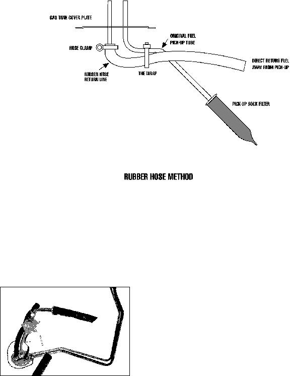
RUBBER RETURN LINE METHOD
Drill a 5/16-inch hole in the sending unit plate adjacent to where the main line enters the tank. This will be the hole for your return line. Insert a short length of 5/16-inch hard line (available at most radiator shops) into the hole and weld it to the sending unit plate. The hard line should extend through the hole 1 to 2 inches on each side of the plate. Connect a length (at least 4 inches) of 5/16-inch rubber return line hose to the hard line that will extend into the tank. Connect the rubber line to the fuel pickup line using tie wraps.
BULKHEAD FITTING METHOD
Drill a 9/16-inch hole in the sending unit plate adjacent to where the main line enters the tank. This will be the hole for your return line. Insert a #6 AN bulkhead fitting (available at most radiator shops) into the hole, the narrow end of the fitting on the inside of the plate. Apply a rubber washer or RTV sealant and fasten the fitting to the plate with the nut. Connect a length (at least 4 inches) of flexible return line (rubber or braided hose) to the fitting end. Connect the return line to the fuel pickup line using tie wraps.
NOTE: THIS METHOD REQUIRES NO WELDING OF THE FUEL SYSTEM.
NOTE: Whichever method you use to install the return fuel line, be careful to keep the end of the line away from the fuel pickup, as shown. Otherwise, aerated return fuel can be drawn into the pickup.
|
7 |
©2005 Edelbrock Corporation |
Rev. 10/05 |
Pro-Flo EFI Installation Instructions |
Brochure No. 63-0115 |
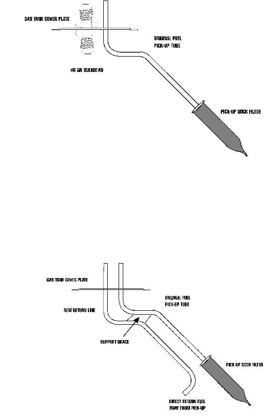
BULKHEAD FITTING METHOD
HARD RETURN LINE METHOD
Drill a 5/16-inch hole in the sending unit plate adjacent to where the main line, enters the tank. This will be the hole for your return line. Insert a length of 5/16-inch hard line (available at most radiator shops) into the hole and weld it to the sending unit plate. The hard line should extend through the hole 1 to 2 inches on the outside of the plate. On the inside of the plate, the hard line should follow the contours of the fuel pickup line. Bend the end of the return line away from the sock on the end of the fuel pickup line. Solder or weld the return hard line to the fuel pickup line.
HARD RETURN LINE METHOD
|
8 |
©2005 Edelbrock Corporation |
Rev. 10/05 |
Pro-Flo EFI Installation Instructions |
Brochure No. 63-0115 |

NOTE: ALL WELDING AND SOLDERING OF THE FUEL SYSTEM MUST BE PERFORMED BY A PROFESSIONAL RADIATOR AND/OR FUEL SYSTEM REPAIR SHOP.
FUEL SYSTEM INSTALLATION
1.Drain the fuel tank.
2.Remove all fuel lines from the tank and from the carburetor.
3.Remove the fuel tank.
NOTE: While the fuel tank is removed from the car, it is recommended that it be professionally cleaned in order to remove any rust or dirt that may have accumulated inside and which could damage the injectors.
4.Remove the sending unit from the fuel tank. Refer to the RETURN FUEL LINE methods above for installing the bypass fuel return line.
5.Install the provided 3/8-inch primary fuel line directly above the original line, which may now serve as a return line. Use large radius bends. Avoid the exhaust pipe and any sharp edges.
NOTE: The 3/8-inch high pressure fuel line supplied with the Pro-Flo system must be used as the primary fuel line.
6.If you do not use the original fuel as the return line, route the return line directly alongside the provided 3/8-inch primary fuel line.
7.Mount the fuel pump between the tank and the fuel filter as low and as close to the fuel tank as possible. The pump is directional. Electrical connectors should face the front of vehicle. The fuel pump needs to be at or below the level of fuel in the tank.
8.Mount the fuel filter between the fuel pump and the engine.
9.Re-install the modified sending unit plate to the clean fuel tank.
10.Reinstall the fuel tank.
11.Attach the primary line and return line to the sending unit plate on the tank.
12.Re-attach all other fuel lines at the tank (vapor purge lines, etc., if so equipped).
13.Secure the primary and return fuel lines with the provided tie-wraps, or with Adel clamps if available.
14.Re-attach all fuel lines to the induction system once it has been installed.
15.Use the 10-foot wiring harness to connect the fuel pump to Connector J3 of the Main System Harness. Route the harness away from the exhaust pipe and any sharp edges. This harness may be cut to length. Replacement terminals are provided with the Pro-Flo system. Cover the connection to the positive terminal with the sleeve and tie wrap provided. Refer to the MAIN SYSTEM HARNESS section of this manual for details.
16.Before starting the engine, turn the ignition key to the ON position 4 or 5 times to prime the electric fuel pump, fuel lines, and fuel rails. You should hear the pump run for approximately 2 seconds each time. Check the entire fuel system for leaks. Refer to the SYSTEM START-UP section of this manual for details.
|
9 |
©2005 Edelbrock Corporation |
Rev. 10/05 |
Pro-Flo EFI Installation Instructions |
Brochure No. 63-0115 |

INDUCTION SYSTEM
The Edelbrock Pro-Flo system delivers fuel and air to the engine via the induction system consisting primarily of a manifold, 4-barrel air valve, fuel rails, and fuel injectors. The induction system is fully assembled, tested, seal checked, and flowed at the factory and is as easy to install as a manifold. DO NOT DISASSEMBLE any of these components during installation.
FUEL RAILS
The extruded aluminum rail assembly routes the high pressure fuel to the injectors.
Aluminum rails have an advantage over soft rails both in terms of style and safety.
INTAKE MANIFOLD
The new Edelbrock manifold used with the Pro-Flo system is very similar to the successful Victor Jr. high-performance single-plane manifold, but has been designed specifically for electronic fuel injection applications.
4-BARREL AIR VALVE
The Pro-Flo system uses a progressive linkage valve body with four throttle blades arranged in a conventional 4-barrel pattern, with staged secondaries. The air valve can flow up to 1000 cfm at 1.5" of mercury when wide open.
FUEL INJECTORS
The Pro-Flo #3550 & 3551 systems use high impedance pintle-type fuel injectors. The injectors used with #3550 are capable of flowing 44 lbs./hr. at 50 psi. The #3551 uses 29 lbs./hr. injectors. The injectors mount directly onto the manifold, one at each port, for fuel delivery that is precisely controlled and instantaneously injected.
|
10 |
©2005 Edelbrock Corporation |
Rev. 10/05 |
Pro-Flo EFI Installation Instructions |
Brochure No. 63-0115 |
PRE-INSTALLATION
Before installing the induction system, take the following steps to ensure successful installation and performance
1.Check all components thoroughly for damage.
2.Make sure all throttle linkages open entirely and close freely.
3.Make sure all fuel inlet and vacuum ports are free from packing material.
4.Check the installation kit for proper parts.
REMOVING THE STOCK CARBURETOR AND MANIFOLD
1.Disconnect battery.
2.For ease of installation, keep all parts in order.
CAUTION: Do not remove manifold if engine is hot.
3.Drain radiator coolant (radiator drain plug is typically located on lower right facing engine).
4.Remove gas cap to relieve pressure. Disconnect fuel line and plug. Replace gas cap.
5.Disconnect all linkage from carburetor such as throttle, throttle springs, transmission, cruise control and automatic choke.
6.Tag and remove coil wires and sensor wires.
7.Remove previously marked vacuum lines.
8.Remove radiator hose, thermostat housing and thermostat, if mounted on manifold.
9.Remove all brackets from the manifold.
10.Loosen or remove valve cover bolts for manifold removal and replacement. It may be necessary to replace valve cover gaskets, if broken, to prevent oil leakage.
PORT SURFACE CLEANING
When cleaning old gaskets from head surfaces, lay rags in the lifter valley and stuff paper into the ports, to prevent pieces of the old gasket from falling into ports and combustion chambers. When clean, remove paper, making sure that all particles fall on the rags in the lifter valley. Remove rags, and wipe surfaces clean with rags soaked in lacquer thinner in order to remove oil or grease. NOTE: This procedure is necessary to ensure proper sealing.
INSTALLING FITTINGS, PIPE PLUGS, AND STUDS
Do not over-tighten or cross-thread fittings, pipe plugs, studs, or bolts in your aluminum manifold. Damage to threads or a cracked mounting boss may result unless caution is used when installing accessories.
Use high quality pipe thread sealant on all threads. Install fittings from your stock manifold.
|
11 |
©2005 Edelbrock Corporation |
Rev. 10/05 |
Pro-Flo EFI Installation Instructions |
Brochure No. 63-0115 |
 Loading...