


U-Handle Kit Installation
Instructions P/N 99944200689
For Models: SRM-280/280S/280T S/N ALL
 WARNING
You must install a Barrier Bar or U-Handle Kit and all Blade Conversion parts shown in the following instructions before operating this unit with blades, otherwise serious injury may result.
IMPORTANT
If non-standard monofilament heads, METAL/PLASTIC blades or cultivators etc., are used, THE CARBURETOR MUST BE RESET or serious engine damage can occur. See "Carburetor Adjustment" in the unit Operator's Manual.
SRM/PAS/SB BLADE SET-UP GUIDE*
TO USE |
|
Pro Maxi-Cut |
Rigid Plastic |
Metal |
Metal 80T Brush Blade |
|
|
Grass/Weed |
Tri-Cut |
Tri-Cut/8 Tooth |
|||
|
Metal 22T Clearing Saw Bla |
|||||
THESE BLADES |
|
Plastic Cutters |
Grass/Weed Blade |
Grass/Weed Blade |
||
|
|
|
||||
|
|
Loop Handle, w/or |
Loop Handle |
Loop Handle |
|
|
|
Handle |
w/Barrier Bar, |
w/Barrier Bar, |
U-Handle |
||
|
w/o Barrier Bar |
|||||
You |
|
or U-Handle |
or U-Handle |
|
||
|
|
|
||||
must |
Debris Shield |
Metal Shield |
Metal Shield |
Metal Shield |
Metal Shield |
|
install |
Harness |
Shoulder Harness |
Shoulder Harness |
Shoulder Harness |
Shoulder Harness**** |
|
these |
||||||
|
Upper Plate & |
Upper Plate |
Upper/Lower |
Upper/Lower |
||
parts! |
Blade |
|||||
|
Flat Washer |
& Glide Cup |
Blade Plates** |
Blade Plates** |
||
|
Mounting |
Hex Nut |
Hex Nut |
Hex Nut |
Hex Nut |
|
|
Hardware |
|||||
|
New Cotter Pin*** |
New Cotter Pin*** |
New Cotter Pin*** |
New Cotter Pin*** |
||
|
|
*WARNING! DO NOT INSTALL BLADES ON GT (CURVED SHAFT) MODEL TRIMMERS
**Arbor diameter of Upper Blade Plate must match arbor diameter of metal blades.
***New cotter pin required each time blade is installed.
****Brushcutters over 16.5 lbs (7.5 kg) dry weight (weight w/o fuel) require a double shoulder harness
Contents
1 U-handle assembly
1Lower u-handle bracket (2 halves)
1Harness clamp w/ring
15 x 12 mm bolt
18 x 55 mm bolt
1Circular washer
1Square nut
2Throttle cable clips
35 x 30 mm bolts w/washers
1 Shoulder harness
1 Hip pad
X7502234701 |
X750011731 |
|
10/09 |
||
|
2 |
U-Handle Kit Installation Instructions |
|
|
|
Installation |
|
|
||
Tools Required: 8mm x 10mm Open End Wrench, 19 mm wrench |
|
|
|
|
|
4 mm hex wrench, screwdriver |
|
|
|
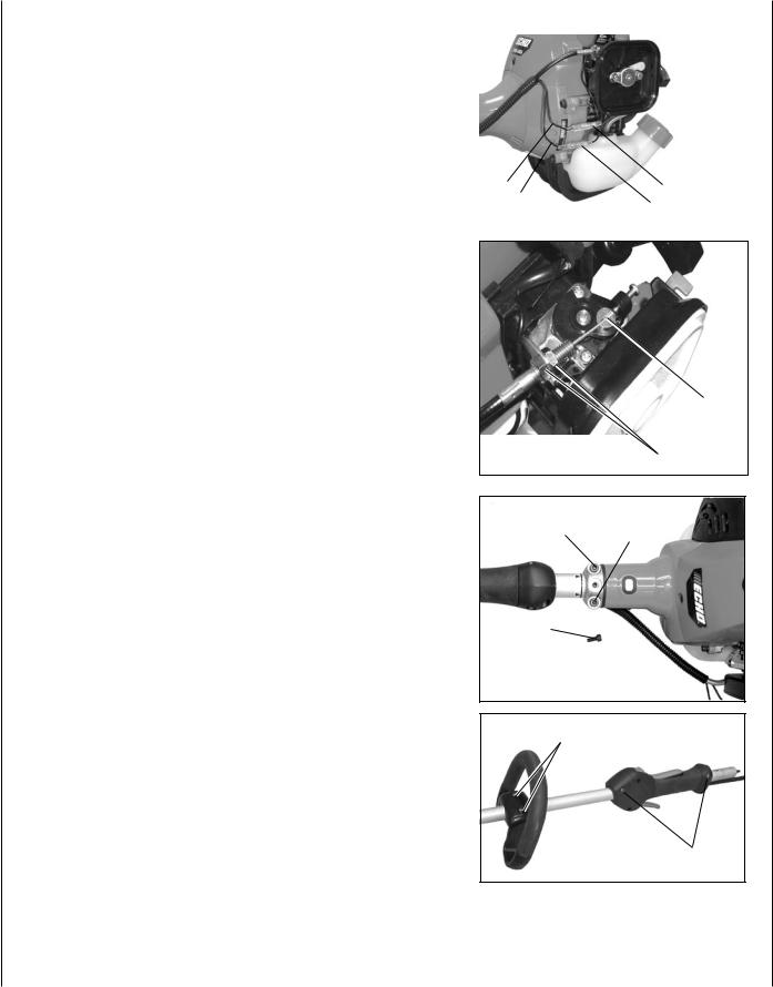
1. |
Close choke and remove air filter and cover. |
|
|
|
2. |
Disconnect ignition stop leads (A) and (B). |
|
|
|
|
|
A |
A |
|
|
|
B |
B |
|
|
|
|
|
|
|
|
|
|
|
3.Loosen nuts (C) and remove throttle linkage from carburetor bracket.
4.Remove inner throttle cable from carburetor swivel (D).
D
C
5.Loosen the two (2) drive shaft clamp bolts (E) at engine drive shaft clamp, and remove center drive shaft location bolt (F).
E E
6.Pull drive shaft assembly from clutch case.
F 
7.Loosen two (2) rear handle screws (G) and pull rear handle from
the drive shaft assembly. |
H |
8.Loosen two (2) screws (H) and remove front handle.
G
U-Handle Kit Installation Instructions |
3 |
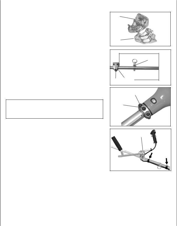
9.Insert square nut (I) in lower handle bracket (J) and place bracket on drive shaft 400mm (15 3/4 in.) from engine end of drive shaft.
10.Secure with lower handle bracket clamp (K) and three (3) 5mm x 30mm hex socket bolts.
11.Position harness clamp (L) 220 mm (8-5/8 in.) from engine end of drive shaft assembly. Install 5x12 mm bolt, but DO NOT tighten at this time.
12.Carefully fit drive shaft assembly to engine making sure inner drive shaft engages into clutch socket.
13.Turn drive shaft housing until locating hole lines up with location hole in clamp and install center drive shaft location bolt (F).
NOTE
Gear Housing must be aligned properly with engine. Aligning center locating hole in driveshaft housing with center drive shaft bolt
(F)provides correct alignment.
14.Tighten two (2) drive shaft clamp bolts (E) securely.
15.Install upper U-Handle and bracket on lower bracket and secure with one (1) 8 mm x 55 mm bolt (M) and large circular washer.
16.Route throttle linkage and ignition lead assembly behind U-Han- dle bracket and clip to drive shaft as shown.
I
J 
K
400 mm
(15-3/4 in.)
L
ENGINE END
K |
J |
|
220 mm |
|
(8-5/8 in.) |
||
|
|||
|
|
|
E
F
 E
E
M
4 |
U-Handle Kit Installation Instructions |
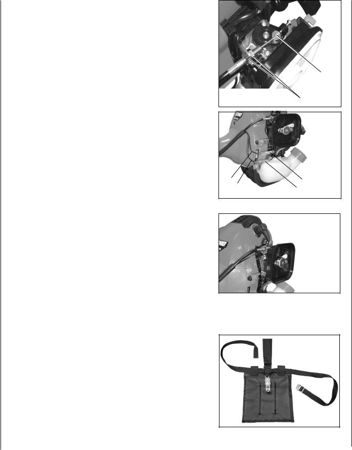
17.Place inner throttle cable in large hole of carburetor swivel (D).
18.Loosen nuts (C) and place threaded end of throttle linkage in bracket slot. Finger tighten nuts (C).
19.Check throttle for freedom of movement and that wide open throttle / low idle extremes are adjusted properly. If adjustment cannot be achieved with adjusting nuts (C), consult with your
Echo Dealer for correct adjustment procedure. Tighten nuts (C).
20.Connect 2 ignition stop leads (A,B) from throttle cable tubing to 2 ignition leads (A,B) on engine.
21.Gather ignition wires and position behind air filter case.
22.Install air filter and cover
D
C
A A B B
Install Hip Pad (Optional)
1.Attach hip pad to harness as shown.
U-Handle Kit Installation Instructions |
5 |
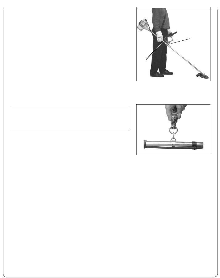
Balance and Adjust Unit
1.Loosen harness clamp screw.
2.Put on harness and attach unit to harness.
N
3.Slide harness clamp (L) up or down until unit balances with head approximately 50-75 mm (2 -3 in.) from the ground.
4.Tighten harness clamp screw.
5. |
Loosen upper U-Handle clamp screws (N), and position U-Handle |
L |
|
||
|
for comfortable operation. |
|
6. |
Tighten U-Handle clamp screws and 8 mm clamp bolt securely. |
|
NOTE
In case of Emergency, the trimmer/brushcutter can be released from the harness by pulling up on the quick-release collar.
echo consumer product support
If you require assistance or have questions concerning the application, operation or maintenance of this product you may call the ECHO Consumer Product Support Department at 1-800-673-1558 from 8:30 am to 4:30 pm (Central Standard Time) Monday through Friday. Before calling, please know the model and serial number of your unit to help your Consumer Product Support Representative.
ECHO, INCORPORATED 400 OAKWOOD ROAD LAKE ZURICH, IL 60047 USA PHONE: 1-800-673-1558 www.echo-usa.com
 Loading...