DYNEX SV1516M, SV1516K, SV1516FM, SV1516FK, SV1514M Datasheet
...
SV15..F
SV15..F
Fast Recovery Diode
Replaces March 1998 version, DS4209-2.2 |
DS4209-3.0 January 2000 |
APPLICATIONS
■Induction Heating
■A.C. Motor Drives
■Snubber Diode
■Welding
■High Frequency Rectification
■UPS
FEATURES
■Thermal Fatigue Free Pressure Contact
■High Surge Capability
■Low Recovery Charge
VOLTAGE RATINGS
Type Number |
Repetitive Peak |
Conditions |
|
Reverse Voltage |
|
|
VRRM |
|
|
V |
|
|
|
|
SV15 16F M or K |
1600 |
VRSM = VRRM + 100V |
SV15 14F M or K |
1400 |
|
SV15 12F M or K |
1200 |
|
SV15 10F M or K |
1000 |
|
SV15 08F M or K |
800 |
|
SV15 06F M or K |
600 |
|
For 1/2" 20 UNF thread, add suffix K, e.g. SV15 16FK. For M12 thread, add suffix M, e.g. SV15 16FM.
For stud anode add 'R' to type number, e.g. SV15 16FMR. For outline DO8C add suffix 'C' to typ number,
e.g. SV15 16FKC.
KEY PARAMETERS
|
|
|
|
|
VRRM |
1600V |
|
|
|
|
|
|
IF(AV) |
205A |
|
|
|
|
|
|
IFSM |
3000A |
|
|
|
|
|
|
Qr |
35 C |
|
|
|
|
|
|
trr |
3.2 s |
|
|
|
|
|
|
|
|
|
|
|
|
|
|
|
|
|
|
|
|
|
|
|
|
|
|
|
|
|
|
|
|
|
|
|
|
|
|
|
|
|
|
|
|
|
|
|
|
|
Outline type codes: DO8 and DO8C.
See Package Details for further information.
CURRENT RATINGS
Symbol |
Parameter |
Conditions |
Max. |
Units |
||
|
|
|
|
|
|
|
I |
Mean forward current |
Half wave resistive load, T |
case |
= 65oC |
205 |
A |
F(AV) |
|
|
|
|
|
|
|
|
|
|
|
|
|
IF(RMS) |
RMS value |
Tcase = 65oC |
|
|
236 |
A |
1/7
SV15..F
SURGE RATINGS
Symbol |
Parameter |
Conditions |
|
|
Max. |
Units |
|
|
|
|
|
|
|
|
|
IFSM |
Surge (non-repetitive) forward current |
10ms half sine; with 0% VRRM, Tj = 150oC |
3.0 |
kA |
|||
I2t |
I2t for fusing |
45 x 103 |
A2s |
||||
|
|
|
|||||
|
|
|
|
|
|
|
|
IFSM |
Surge (non-repetitive) forward current |
10ms half sine; with 50% V |
T |
= 150oC |
- |
kA |
|
|
|
|
|
||||
I2t |
I2t for fusing |
RRM, |
j |
|
- |
A2s |
|
|
|
|
|||||
|
|
|
|
|
|
|
|
THERMAL AND MECHANICAL DATA
Symbol |
Parameter |
Conditions |
|
Min. |
Max. |
Units |
|
|
|
|
|
|
|
Rth(j-c) |
Thermal resistance - junction to case |
|
dc |
- |
0.23 |
oC/W |
Rth(c-h) |
Thermal resistance - case to heatsink |
Mounting torque 15Nm |
|
- |
0.02 |
oC/W |
|
|
with mounting compound |
|
|
|
|
|
|
|
|
|
|
|
Tvj |
Virtual junction temperature |
On-state (conducting) |
|
- |
150 |
oC |
Tstg |
Storage temperature range |
|
|
-55 |
200 |
oC |
- |
Mounting torque |
|
|
12.0 |
15.0 |
Nm |
|
|
|
|
|
|
|
CHARACTERISTICS
Symbol |
Parameter |
|
|
|
|
Conditions |
Typ. |
Max. |
Units |
|
|
|
|
|
|
|
|||||
VFM |
Forward voltage |
At 450A peak, Tcase = 25oC |
- |
1.6 |
V |
|||||
I |
|
Peak reverse current |
At V |
|
, T |
case |
= 150oC |
- |
20 |
mA |
RRM |
|
RRM |
|
|
|
|
|
|||
|
|
|
|
|
|
|
|
|
|
|
trr |
Reverse recovery time |
|
|
|
|
|
- |
3.2 |
s |
|
QRA1 |
Recovered charge (50% chord) |
IF = 450A, diRR/dt = 10A/µ s |
- |
35 |
µ C |
|||||
IRM |
Reverse recovery current |
Tcase = 125oC, VR = 100V |
- |
21 |
A |
|||||
K |
Soft factor |
|
|
|
|
|
- |
- |
- |
|
|
|
|
|
|
|
|
|
|||
V |
TO |
Threshold voltage |
At T |
= 150oC |
- |
1.0 |
V |
|||
|
|
vj |
|
|
|
|
|
|
|
|
|
|
|
|
|
|
|
|
|||
r |
T |
Slope resistance |
At T |
= 150oC |
- |
1.33 |
mΩ |
|||
|
|
vj |
|
|
|
|
|
|
|
|
|
|
|
|
|
|
|||||
VFRM |
Forward recovery voltage |
di/dt = 1000A/µ s, Tj = 125oC |
- |
- |
V |
|||||
2/7

SV15..F
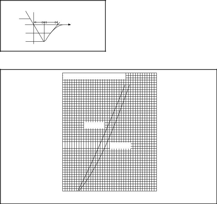
DEFINITION OF K FACTOR AND QRA1
QRA1 = 0.5x IRR(t1 + t2)
dIR/dt |
t2 |
k = t1/t2 |
t1 |
τ |
|
|
|
|
0.5x IRR |
|
|
IRR |
|
|
CURVES
F
Instantaneous forward current I - (A)
3000 


 Measured under pulse conditions
2500
2000
Tj = 25˚C
1500  Tj = 150˚C
1000
500 |
|
|
|
|
1.0 |
2.0 |
3.0 |
4.0 |
5.0 |
Instantaneous forward voltage VF - (V)
Fig.1 Maximum (limit) forward characteristics
3/7
 Loading...