


BEDIENUNGSANLEITUNG
OWNER’S MANUAL
MODE D’EMPLOI
Po w e r M ate 1000/1600/2200 |
POWER MIXER

C O N T E N T S
Introduction . . . . . . . . . . . . . . . . . . . . . . . . . . . . . . . . . . . . . . . . . . . . . . . . . . . . . . . . . . . . . . . . . . . 31
Input/Mono . . . . . . . . . . . . . . . . . . . . . . . . . . . . . . . . . . . . . . . . . . . . . . . . . . . . . . . . . . . . . . . . . . . 32
Input/Stereo . . . . . . . . . . . . . . . . . . . . . . . . . . . . . . . . . . . . . . . . . . . . . . . . . . . . . . . . . . . . . . . . . . 37
Effect. . . . . . . . . . . . . . . . . . . . . . . . . . . . . . . . . . . . . . . . . . . . . . . . . . . . . . . . . . . . . . . . . . . . . . . . 40
AUX3 . . . . . . . . . . . . . . . . . . . . . . . . . . . . . . . . . . . . . . . . . . . . . . . . . . . . . . . . . . . . . . . . . . . . . . . 42
Phones + Mono Out + Standby . . . . . . . . . . . . . . . . . . . . . . . . . . . . . . . . . . . . . . . . . . . . . . . . . . . 43
Master + Power Amplifier . . . . . . . . . . . . . . . . . . . . . . . . . . . . . . . . . . . . . . . . . . . . . . . . . . . . . . . . 44
Rear panel . . . . . . . . . . . . . . . . . . . . . . . . . . . . . . . . . . . . . . . . . . . . . . . . . . . . . . . . . . . . . . . . . . . 49
Standard installation + Master patchbay and installation alternatives . . . . . . . . . . . . . . . . . . . . . . 50
Specifications . . . . . . . . . . . . . . . . . . . . . . . . . . . . . . . . . . . . . . . . . . . . . . . . . . . . . . . . . . . . . . . . . 57
Block diagram . . . . . . . . . . . . . . . . . . . . . . . . . . . . . . . . . . . . . . . . . . . . . . . . . . . . . . . . . . . . . . . . . 86
Dimensions . . . . . . . . . . . . . . . . . . . . . . . . . . . . . . . . . . . . . . . . . . . . . . . . . . . . . . . . . . . . . . . . . . . 87
Warranty . . . . . . . . . . . . . . . . . . . . . . . . . . . . . . . . . . . . . . . . . . . . . . . . . . . . . . . . . . . . . . . . . . . . . 88
IMPORTANT SAFETY INSTRUCTIONS
The lightning flash with arrowhead symbol, within an equilateral triangle is intended to alert the user to the presence of uninsulated “dangerous voltage” within the product’s enclosure that may be of sufficient magnitude to constitute a risk of electric shock to persons.
The exclamation point within an equilateral triangle is intended to alert the user to the presence of important operating and maintance (servicing) instructions in the literature accompanying the appliance.
1.Read these instructions.
2.Keep these instructions.
3.Heed all warnings.
4.Follow all instructions.
5.Do not use this apparatus near water. Do not expose this apparatus to dripping or splashing and ensure that no objects filled with liquids, such as vases, ase placed on this apparatus.
6.Clean only with a dry cloth.
7.Do not block any of the ventilation openings. Install in accordance with the manufactures instructions.
8.Do not install near any heat sources such as radiators, heat registers, stoves, or other apparatus that produce heat.
9.Only use attachments/accessories specified by the manufacturer.
10.Refer all servicing to qualified service personnel. Servicing is required when the apparatus has been damaged in any way, such as power-supply cord or plug is damaged, liquid has been spilled or objects have fallen into the apparatus,
the apparatus has been exposed to rain or moisture, does not operate normally, or has been dropped.
For US and CANADA only:
Do not defeat the safety purpose of the grounding-type plug. A grounding type plug has two blades and a third grounding prong. The wide blade or the third prong are provided for your safety. When the provided plug does not fit into your outlet, consult an electrican for replacement of the absolete outlet.
IMPORTANT SERVICE INSTRUCTIONS
CAUTION: These servicing instructions are for use by qualified personnel only. To reduce the risk of electric shock, do not perform any servicing other than that contained in the Operating Instructions unless you are qualified to do so. Refer all servicing to qualified service personnel.
1.Security regulations as stated in the EN 60065 (VDE 0860 / IEC 65) and the CSA E65 - 94 have to be obeyed when servicing the appliance.
2.Use of a mains separator transformer is mandatory during maintenance while the appliance is opened, needs to be operated and is connected to the mains
3.Switch off the power before retrofitting any extensions, changing the mains voltage or the output voltage.
4.The minimum distance between parts carrying mains voltage and any accessible metal piece (metal enclosure), respectively between the mains poles has to be 3 mm and needs to be minded at all times.
The minimum distance between parts carrying mains voltage and any switches or breakers that are not connected to the mains (secondary parts) has to be 6 mm and needs to be minded at all times.
5.Replacing special components that are marked in the circuit diagram using the security symbol (Note) is only permissible when using original parts.
6.Altering the circuitry without prior consent or advice is not legitimate.
7.Any work security regulations that are applicable at the location where the appliance is being serviced have to be strictly obeyed. This applies also to any regulations about the work place itself.
8.All instructions concerning the handling of MOS - circuits have to be observed.
Note: |
SAFETY COMPONENT (HAS TO BE REPLACED WITH ORIGINAL PART ONLY) |
30

INTRODUCTION
First of all, we would like to thank you and congratulate you to your purchase of a DYNACORD power mixer.
The PowerMate compact power mixers incorporate profound Know-How, based on our research and development in the professional audio market as well as on the inter-communication with our clients, for decades. With a PowerMate you own a power mixer that offers a wide range of functionality in a very compact frame. All the troubling experiences with cabling and matching mixers, amplifiers, FX units, and equalizers is history. You now own a device with optimally matched components.
The mixer’s ergonomic shape and clearly structured controls allow instant access at all times. In case the console is operated in areas with insufficient lighting, a gooseneck lamp can be easily plugged into the provided socket. Also during the transport you will quickly learn to appreciate the PowerMate’s superiority: recessed handles on both sides, compact dimensions and low weight. In addition, a sturdy dust hood protects the controls against damaging. On the other hand, the PowerMate can be easily mounted in a 19" rack shelf. You just have to replace the plastic side panels by a pair of metal rack mount ears.
Through its multiple functions, its high dynamic capacity, and extremely low-noise design in combination with its 18bit-Dual-Stereo FX unit and the powerful amplifier, the PowerMate is best equipped for universal use. No matter, whether on-stage, in a home recording environment or in a permanent installation, DYNACORD’s PowerMate is the ideal partner to meet your expectations of a professional audio device – effective and reliable.
Of course, you want to operate your new PowerMate as quickly as possible. But please, take your time to read about all connections, functions, and controls, first. Every section is explained systematically and in detail within this owner’s manual: the input channels, the FX units and the master section as well as the built-in power amplifier. Through the careful perception of the manual you will learn a great deal about all functions and find some useful and practical tips for the daily operation of the PowerMate. Even more important, you will find some adjustment guidelines that should be painstakingly carried out; plus the description of a typical sound reinforcement installation, a block diagram, specifications, connection guidelines, etc.… So, take your time and keep on reading.
UNPACKING AND WARRANTY
Open the packaging and take out the PowerMate. Detach the FX unit displays’ protective foil. In addition to this owner’s manual you will find the mains supply cord and the warranty card. Please check, if the warranty registration form is filled out correctly. Only when this form is completed, you will be able to apply for warranty claims. We grant 36 months of warranty, starting with the date of purchase. Therefore, we would like to ask you to also keep the original certificate of purchase together with the warranty certificate.
Keeping all papers and the original packaging of the device is always recommendable. Not only do they come in handy in case of a warranty claim but also when re-selling an appliance.
INSTALLATION AND CONNECTIONS
Always install the PowerMate on an even surface to allow for sufficient airflow during the operation. The device is equipped with electronically controlled ventilators to protect the power amplifier against thermal overload. The direction of the airflow is front to rear. Fresh, cold air enters the mixer at its lower front side and warm air leaves the device through the ventilation louvres in the rear panel. Do not cover the frontal or the rear ventilation louvres. Otherwise the PowerMate automatically enters the protect mode to prevent a thermal overload situation. When the protect mode is engaged, the device is not going to be damaged. But during this period of time regular operation is impossible.
In case the PowerMate is installed in a 19" rack system, you have to allow at least 2 HU of free space above and 1 HU below the device. Of course you can cover the empty space with special plates that also have ventilation louvres. Before establishing the mains supply connection, please make sure that the device matchesthe voltage and frequency of your local mains supply. Check the label next to the mains switch. When switching the power on, the internal ventilators will run for about 2 seconds at full speed to give you an acoustical signal that the PowerMate entered the operation mode. In addition dust particles that might have gotten into the device get blown out.
For a secure connection the speaker outputs on the PowerMate’s rear panel are provided through professional standard Speakon connectors. The pin assignment of these sockets is 1+ (hot) and 1- (cold).
31
INPUT/MONO
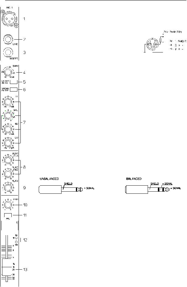
1. MIC
Electronically balanced XLR-type inputs for the connection of low impedance microphones, likewise the ones that are featured in major studio and live mixing consoles. This type of input stage provides extraordinary low noise signal conversion at an extremely low distortion rate (typical <002%) even in the high frequency range.
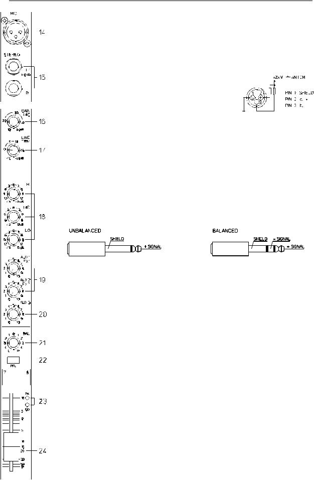
Generally, any type of microphone can be connected as long as its pin assignment is in accordance to the diagram shown aside. When condenser microphones are connected, you have to press the
PHANTOM button which is located in the master section. The microphone gets its operational voltage (+24Vdc) through the mixer and you can forget about battery replacement times.
CAUTION: Make sure to always connect the microphones before turning on the phantom power or switching the PowerMate on with activated phantom power. This is the only way to certify that your microphones are not damaged. Also make sure to engage the stand-by button in the master section to safe yourself and your environment from nasty power-on noise.
The connection of condenser type microphones and dynamic microphone models at the same time is possible and should generally not lead to any problems. Before you do so, please refer to the microphone’s manual to make sure that this kind of operation is in accordance to the manufacturer’s guidelines.
The MIC input is laid out for levels between –60dBu … +11dBu – depending on the setting of the corresponding gain control. Because of their low impedance design and the phantom power these XLR-type inputs are not meant for cascading other mixing consoles or the connection of FX units, keyboards or other electronic equipment. When connecting this kind of equipment, please use the LINE level inputs.
2. LINE
Electronically balanced inputs for the connection of electronic instruments, such as keyboards, drum machines, E-guitars and E-basses with an active output, as well as all other high level signal sources, like additional mixers, FX units, CD player, etc.
The LINE input is laid out for levels between –40dBu … +30dBu. The connection of balanced or unbalanced signal sources is established through monaural or stereo phone plugs, assigned according to the diagram below. If the device that you want to connect has a balanced output stage, the use of balanced cables with stereo phone plugs is preferable. This type of connection is greatly insensitive to the induction of external noise or HF interference.
Do not connect signal sources to the MIC and the LINE inputs at the same time, since the signals would interfere with each other, resulting in a level reduction.
One more note: Please, do not connect E-guitars or E-basses with passive, high impedance outputs directly to one of the LINE inputs. The LINE inputs of the PowerMate – like the Line level inputs of mixers from all other manufacturers – are meant for the connection of the relatively low source impedance of electronic instruments or eqiupment. The reproduction of the instrument’s original sound characteristics will be unsatisfactory – unless this effect is intended. Those instruments should be connected using a special transformer or pre-amplifier with very high input impedance. Musical instruments that are equipped with an active electronic output stage (battery) can be connected without second thoughts.
When connecting signal sources, please make sure that the corresponding channel faders or at least the master faders are at their minimal settings or the STANDBY button is engaged. This will save you, your audience, and the equipment from extensive wear from unpleasant knacking noise.
32
INPUT/MONO
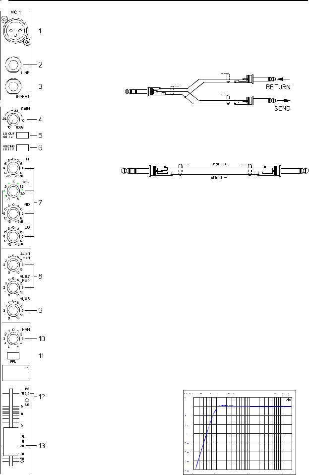
3. INSERT
Stereo phone jack with breaker function. The low impedance output is assigned to the tip (send) and the high impedance input (return) is assigned to the ring (body). This jack allows the connection of external compressors, limiters, EQs, de-noisers, etc. into the corresponding channel’s signal path. The insertion point is post gain controls, Lo-Cut filters, and voicing stage and pre sound shaping section and faders. You have to use a stereo phone plug – according to the following diagram – in case you intend to use this jack as a true insert bus.
INSERT
If you want to use this socket as a DIRECT OUT (Pre EQ), the stereo phone plug’s tip and ring have to be short circuited, so that the audio signal is not interrupted. If you are using a monaural phone plug instead, you will get a DIRECT OUT with breaker function – the signal flow within the channel is interrupted.
DIRECT OUT
4. GAIN
Rotary control to adjust the MIC/LINE inputs’ sensitivity. These controls let you optimally adjust the incoming signals to the mixer’s internal operation level. Cautious adjusting offers the benefits of an improved S/N-ration and provides you with the full bandwidth of the PowerMate’s outstanding sound capabilities. On the XLR-type connectors an amplification of +10dB is achieved when the control is set all the way to the left and +60dB when the control is set all the way to the right. Especially when dealing with very low input levels, like they occur during vocal recordings or when the sound source is located in a distance, the high gain is extremely profitable. Using the LINE-input, the signal is generally attenuated by –20 dB. The total adjustment range of 50dB stays the same. The LINE-input’s unity gain – no amplification (0 dB) – is achieved at the 20dB mark. The following is meant as a short note for your assistance on how to determine the right input level:
Note on how to adjust the input level:
1. Set the gain control and the corresponding channel fader to their lowest setting. 2.Connect the desired sound source (microphone, musical instrument, etc.) to the MIC or LINE input.
3.Play the sound source at its highest volume – respectively sing or speak as loud as possible directly into the microphone.
4.While you are playing the sound source or singing into the microphone, adjust the input level using the gain control, so that during the loudest passages the PEAK LED is just not lit, but
the SIGNAL - LED lights constantly.
This is the basic channel setting, leaving you with at least 6dB of headroom. Which means, you have at least a range of 6dB before signal clipping. In case you intend to make further adjustments to the channel’s EQ setting, you should perform the steps 3. and 4. again afterwards, since changes in the sound shaping section also influence the channel’s overall level.
5. LO CUT 80 Hz
When the LO CUT switch is engaged, frequencies below 80 Hz are attenuated (18dB octave). In most cases using the LO CUT filter with microphone channels is a good advice, since it efficiently surpresses popping sounds and rumbling noise. The only exceptions are kick drum and acoustic bass.
33
INPUT/MONO
Sometimes it can be also very effective to combine the LO CUT filter with the VOICING filter. For instance to provide a “thin” voice with more “body”, without getting additional low pitched noise. Whenever the LO CUT is engaged, raising the bass level (LO EQ) provides you with a richer sound, but no additional rumbling or popping noise.
Another welcome side effect is, that the power amplifier and the connected loudspeakers do not get “polluted” with unnecessary low pitched noise. And the audience will be thankful for the use of the LO CUT filter, too. Since in this way they can enjoy a truly clear, natural, and powerful sound performance.
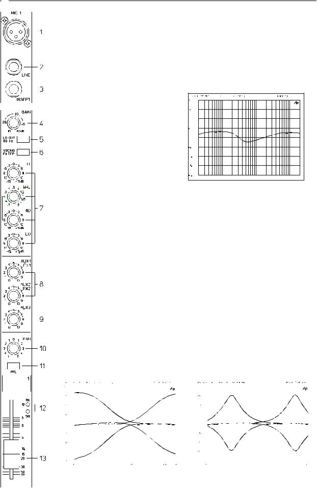
6. VOICING FILTER
This button activates an asymmetric micro-
phone filter, which can be used in addition to the channel EQ. The VOICING filter en-
hances the first harmonic oscillation of the human voice and slightly attenuates the mid
frequency range. This voice shaping me-
thod provides precisely audible, intelligible,
and powerful vocals that are clearly emphasized from the rest of the mix. An effect
which is not achievable using ordinary third or octave equalizers.
The use of this filter is not restricted to vocals 


 only. Also horns, woodwinds, and other acoustic instruments can profit from the voicing filter.
We leave it entirely up to your creativity and imagination to try the filter with as many different sound sources as you want. Normally, you do not have to fear any problems with the occurrence of feedback.
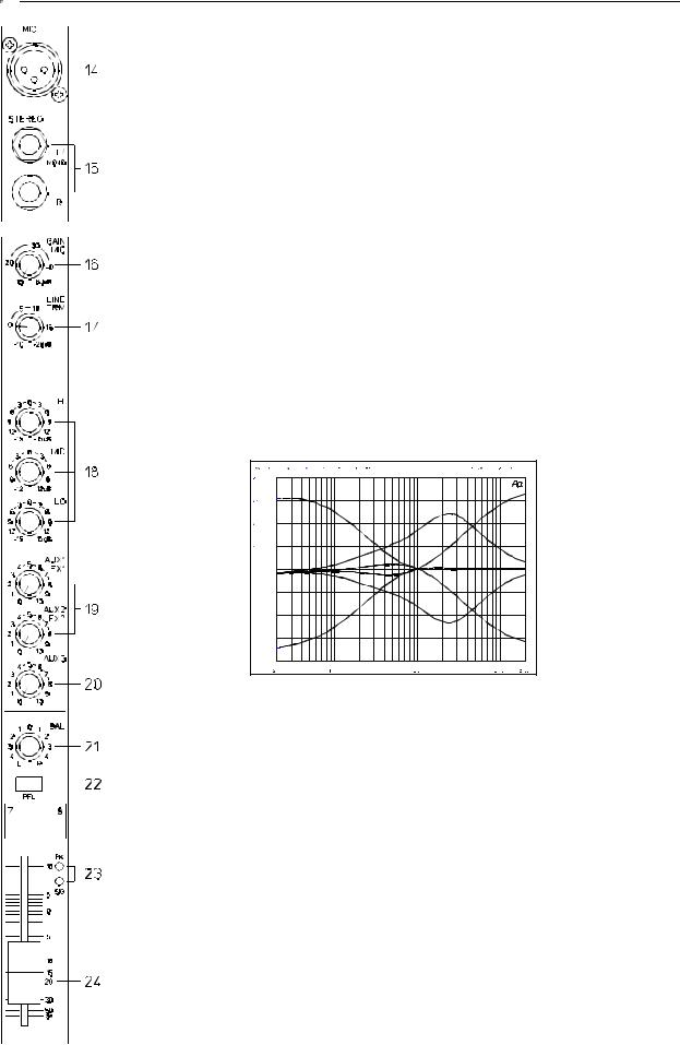
7. EQ SECTION
The mixer’s EQ section allows very differentiated shaping of the incoming audio signal within miscellaneous frequency bands. Turning one of the EQ level controls to the right enhances/amplifies the corresponding frequency range while turning them to the left lowers/attenuates the signal of the specific frequency band. Before you begin to alter the sound, all EQ controls should be set to their neutral position; that is: their marker points straight up (locked in place). Do not set the EQ controls to extreme positions. Usually, minor changes are totally sufficient and produce the best results in the overall sound. You should use the natural reproduction as an orientation mark and rely on your musically trained ear, being the perfect instrument to judge the sound quality. The moderate use of the MID control is the best remedy to avoid acoustical feedback. Especially in this frequency range you should try to avoid excessive enhancement. Lowering the level more or less in this band will provide you with high amplification rates without feedback.
Use the LO control according to your pleasing, to add more “punch” to the sound of a kick drum or “body” to the vocals. Use the HI control in the same way to provide cymbals and the human voice with more treble and a more transparent sound. The MID EQ section offers separate rotary controls for the adjustment of the level (MID) and the frequency band (kHz) between 100 Hz and 8 kHz.
|
|
|
|
|
|
|
|
|
|
|
|
|
|
|
|
|
|
|
|
|
|
|
|
|
|
|
|
|
|
|
|
|
|
|
|
|
|
|
|
|
|
|
|
|
|
|
|
|
|
|
|
|
|
|
|
|
|
|
|
|
|
|
|
|
|
|
|
|
|
|
|
|
|
|
|
|
|
|
|
|
|
|
|
|
|
|
|
|
|
|
|
|
|
|
|
|
|
|
|
|
|
|
|
|
|
|
|
|
|
|
|
|
|
|
|
|
|
|
|
|
|
|
|
|
|
|
|
|
|
|
|
|
|
|
|
|
|
|
|
|
|
|
|
|
|
|
|
|
|
|
|
|
|
|
|
|
|
|
|
|
|
|
|
|
|
|
|
|
|
|
|
|
|
|
|
|
|
|
|
|
|
|
|
|
|
|
|
|
|
|
|
|
|
|
|
|
|
|
|
|
|
|
|
|
|
|
|
|
|
|
|
|
|
|
|
|
|
|
|
|
|
|
|
|
|
|
|
|
|
|
|
|
|
|
|
|
|
|
|
|
|
|
|
|
|
|
|
|
|
|
|
|
|
|
|
|
|
|
|
|
|
|
|
|
|
|
|
|
|
|
|
|
|
|
|
|
|
|
|
|
|
|
|
|
|
|
|
|
|
|
|
|
|
|
|
|
|
|
|
|
|
|
|
|
|
|
|
|
|
|
|
|
|
|
|
|
|
|
|
|
|
|
|
|
|
|
|
|
|
|
|
|
|
|
|
|
|
|
|
|
|
|
|
|
|
|
|
|
|
|
|
|
|
|
|
|
|
|
|
|
|
|
|
|
|
|
|
|
|
|
|
|
|
|
|
|
|
|
|
|
|
|
|
|
|
|
|
|
|
|
|
|
|
|
|
|
|
|
|
|
|
|
|
|
|
|
|
|
|
|
|
|
|
|
|
|
|
|
|
|
|
|
|
|
|
|
|
|
|
|
|
|
|
|
|
|
|
|
|
|
|
|
|
|
|
|
|
|
|
|
|
|
|
|
|
|
|
|
|
|
|
|
|
|
|
|
|
|
|
|
|
|
|
|
|
|
|
|
|
|
|
|
|
|
|
|
|
|
|
|
|
|
|
|
|
|
|
|
|
|
|
|
|
|
|
|
|
|
|
|
|
|
|
|
|
|
|
|
|
|
|
|
|
|
|
|
|
|
|
|
|
|
|
|
|
|
|
|
|
|
|
|
|
|
|
|
|
|
|
|
|
|
|
|
|
|
|
|
|
|
|
|
|
|
|
|
|
|
|
|
|
|
|
|
|
|
|
|
|
|
|
|
|
|
|
|
|
|
|
|
|
|
|
|
|
|
|
|
|
|
|
|
|
|
|
|
|
|
|
|
|
|
|
|
|
|
|
|
|
|
|
|
|
|
|
|
|
|
|
|
|
|
|
|
|
|
|
|
|
|
|
|
|
|
|
|
|
|
|
|
|
|
|
|
|
|
|
|
|
|
|
|
|
|
|
|
|
|
|
|
|
|
|
|
|
|
|
|
|
|
|
|
|
|
|
|
|
|
|
|
|
|
|
|
|
|
|
|
|
|
|
|
|
|
|
|
|
|
|
|
|
|
|
|
|
|
|
|
|
|
|
|
|
|
|
|
|
|
|
|
|
|
|
|
|
|
|
|
|
|
|
|
|
|
|
|
|
|
|
|
|
|
|
|
|
|
|
|
|
|
|
|
|
|
|
|
|
|
|
|
|
|
|
|
|
|
|
|
|
|
|
|
|
|
|
|
|
|
|
|
|
|
|
|
|
|
|
|
|
|
|
|
|
|
|
|
|
|
|
|
|
|
|
|
|
|
|
|
|
|
|
|
|
|
|
|
|
|
|
|
|
|
|
|
|
|
|
|
|
|
|
|
|
|
|
|
|
|
|
|
|
|
|
|
|
|
|
|
|
|
|
|
|
|
|
|
|
|
|
|
|
|
|
|
|
|
|
LOW-HI EQ |
|
|
|
|
|
|
|
|
|
|
|
|
|
|
|
|
|
|
|
|
|
|
MID EQ |
|
|||||||||||||||||||||||||||||||||||||||||||||
34

INPUT/MONO
Adjustments in the MID range are certainly the most effective way to shape the sound. As a matter of fact, determining the correct center frequency is not always as easy as it seems. Here is one method – amongst others – how to quickly find the right setting of the parametric EQ for your application.
Note on how to adjust the parametric EQ:
1.Slightly lower the channel fader to avoid feedback.
2.Turn the MID rotary control all the way to the right (+15dB). 3.Play the desired sound source or talk into the microphone.
4.Meanwhile turn the frequency rotary control (kHz) slowly from left to right.
5.Surely and within no time, you will detect the frequency range that is not to your liking or causing feedback.
6.Leave the frequency control in this position and turn the MID control to the left until the sound is natural or to your liking.
It is a different story when you want to enhance a specific frequency range. In this case perform steps 1 to 4 as described above. Set the frequency rotary control to the range you want to enhance or leave it at the position where the sound is most satisfactory. Now you can use the MID control to determine the amount of the alteration.
8. AUX/FX
The AUX/FX controls are used to adjust individual amounts of the channel signals to be routed to the FX1 or the FX2 units. The split point of the “dry” signal is POST FADE or in other words: the signal path is split after the audio signal has passed all stages of the channel module, including the volume fader. That is the reason why the fader setting also influences the amount of the signal that is fed to the FX units. Using the AUX/FX controls it is easy to establish an effect mix. For instance, you can assign the short reverb effect of the FX1 unit to the lead vocals and a combined effect program – echo, hall, and chorus – via FX2 to the background vocals. To determine the desired intensity of each effect, you should start with the controls set at their center and make individual adjustments from there on. Also keep in mind that there are two AUX/FX1/2 send controls located within the master section which control the total amount of the FX signals. When you begin to establish the effect mix these controls should also be set at their center position.
In case you are not using the internal FX units and/or you want to connect external signal processing units, the pre-mixed AUX/FX1/2 signals are outputted via the AUX1/2 send jacks. Please monitor the PEAK LEDs in the FX1/2 channels. The indicator should only light briefly at the occurrence of high program peaks. If the indicator is constantly lit, you should lower the send levels of those channels where the program peaks occur. For further information, please read the paragraphs about the FX1/2 units.
9. AUX 3
The AUX 3 control is primarily meant for the monitor mix. Nevertheless, when the master section’s AUX3 POST button is pressed, it can also be used as a third FX send bus. In that case the signal is split post fader and outputted via the AUX 3 send jack.
To establish a monitor mix you can choose between two alternatives. The main difference of the two options is the point where the signal gets split up; according to the setting of the AUX3 POST button.
The AUX3 POST button is not engaged: the signal split lies PRE FADER – the setting of the channel faders does not affect the signal level that is present at the AUX3 rotary controls. Since the monitor mix is not influenced by the setting of the channel faders, this alternative is primarily used when the main mix and the monitor mix have to be completely different – the volume of specific musical instruments or vocals needs to be higher or lower or should not appear at all in the monitor mix. This mode is also preferable when the PowerMate is operated by a technician in the audience area (front ofhouse).
The other alternative should be used when you have to operate the mixer on-stage and still want to have control over the main mix.
35
INPUT/MONO
The AUX3 POST button is engaged (LED is lit): the signal at the AUX3 rotary control is POST FADER – the signal gets split after it passed the channel faders and therefore is affected by their settings. Setting all AUX3 controls to their center position, the main mix is also present on the monitor bus, giving you the opportunity to control the volume settings individually from the stage. The overall volume of the monitor mix is set with the AUX3 fader in the master section. If you are using this option you have to keep in mind that all volume changes made with the channel faders also appear in the monitor mix, leaving you with a higher risk of acoustical feedback.
To reduce the risk of feedback you still have the option to adjust the individual send levels via the channels’ AUX3 rotary controls. There is even the possibility to cancel some loud instruments – like the kick drum or the snare drum, which are in fact already loud enough on-stage – totally from the monitor mix by turning the corresponding controls all the way to the left.
10. PAN
This control determines the position of the connected sound source within the stereo image. When this control is set at its center position, the audio signal is fed with equal levels to the left and the right master busses. Through the extensive PAN section circuitry the essential sound pressure level always stays the same, no matter to what position within the stereo image the PAN control is set.
11. PFL
Engaging the PFL button (Pre Fader Listening) routes the audio signal of the corresponding channel to the headphone bus. In this way you can route as many signals as you want to the bus at the same time. The volume levels of the individual signals are not affected by the channel fader settings – PRE FADER LISTENING. This gives you the opportunity to set the level or the EQ of a channel without the need to include it in the main mix. The overall signal of the headphone bus is present at the headphone output.
12. SIGNAL (present) / PEAK indicator
This indicator plays a key role during the level adjustment of the input channels, offering optical information of the actual signal level. It provides the possibility to detect the risk of occurring overdrive before you would actually hear the distortion. Unlike the mixers of many other manufacturers that either only provide a PEAK indicator or no channel indicator at all.
As described before, the signal “present” LED should blink in the rhythm of the incoming signal. If this is not the case, you have to increase the gain. If the PEAK LED, on the other hand, blinks frequently or lights up constantly, the corresponding channel is likely to enter clipping and you have to turn the gain control a bit to the left. The signal “present” LED lights at levels –30dB below clipping while the peak LED lights at a level of –6dB below the occurrence of overdrive.
It is also a good idea to watch the indicator during a performance. There is rumor that during a performance some musicians get carried away by the music and the atmosphere. They tend to play their instruments more dynamic than during the rehearsal. This, of course, can easily lead to channel clipping, resulting in the degradation of the overall sound.
13. VOLUME
The channel faders are used to set the volume of the corresponding channels and to establish an accurately proportioned mix. The channel faders should be positioned within the range of –5dB to 0dB, leaving you with a degree of control that allows the precise matching of relative big differences in the channels’ level settings. The overall volume is set through the use of the master faders.
Even though the channel faders offer an additional gain of +10dB, we would like to advise you not to exceed the +5dB mark. If the PowerMate’s main bus gets “overloaded” with too many “high level” input channels, despite its special negative gain structure, the summing amplifier could be driven into clipping. Once you register, that some channel faders are set above the 0dB marking, we would recommend you lower the setting of each channel fader by about –5dB and increase the overall output level by elevating the master faders. The proportion of the mix and the overall volume stay the same while the risk of clipping is prohibited.
36
INPUT/STEREO
Since most features of the stereo inputs are virtually identical to the ones of the monaural inputs, we will not discuss their functioning in detail again. Thus, we only point out the differences and ask you to refer to the analogous paragraphs in the first chapter of this owner’s manual.
14. MIC
Like their monaural counterparts the stereo input channels of the PowerMate incorporate extensive circuitry and electronically balanced XLR-type connectors for the
connection of low impedance microphones. A feature that often enough is not supported on mixers from other manufacturers. No
matter if your setup is more microphone-oriented or you have more line level sound sources to connect, you can always use the full amount of input channels, provided by your PowerMate. The functioning principles were already discussed in detail in the
previous chapter.
15. STEREO INPUT L/MONO R
Electronically balanced inputs for the connection of musical instruments with stereo output, like keyboards, drum machines, E-guitars and E-basses with an active output as well as all other equivalent sound sources with high level outputs, like additional mixing consoles, FX units, CD players, etc.
The stereo LINE input is meant for balanced or unbalanced sound sources with levels between –20dBu and +30dBu. For the connection of external devices you can use monaural or stereo phone plugs which are in accordance to the diagram below. If the external appliance is equipped with a balanced output stage, you should preferably use balanced cables and plugs, since this type of connection provides better shielding against HF induction and external noise.
In case you want to connect a monaural sound source to a stereo input channel, you just have to plug it into the L/MONO input. The signal gets internally routed to both channels. For further information, please refer to the chapter “INPUT/MONO”.
16. GAIN MIC
Rotary control to adjust the MIC inputs’ sensitivity, providing the possibility to optimally match the incoming signals with the mixer’s internal operation level. The GAIN MIC control is only active for the XLR-type connections of the stereo input channels.
Adjustment and functioning of these controls are identical to those of the monaural inputs. CAUTION: The GAIN MIC control of an inactive microphone input should always be set to its minimal marking. Otherwise the noise of the inactive input is added to the audio signal of the corresponding LINE input, which could lead to unnecessary extra noise at the main output, becoming clearly audible in program breaks.
17. LINE TRIM
These rotary controls are used to match the incoming line level signals with the operational level of the PowerMate. The total adjustment range is 30dB. Unity gain – no amplification (0 dB) – is achieved at the 0dB mark. The control offers a level reduction of the incoming signal by –20dB and an amplification of +20dB. This range is wide enough to allow the connection of most professional, semi professional, and even hi-fi sound sources.
For further details on how to adjust the LINE TRIM control, please refer to paragraph 4. GAIN.
If you use a keyboard as sound source on one of the stereo inputs, make sure that no split zones or layers with channel separation are activated. Otherwise the stereo channel mapping will appear like it is set on the keyboard and you will not have the opportunity to re-position the sound in the overall stereo image, using the controls of the mixer. The better alternative to connect a keyboard
37
INPUT/STEREO
with pre-programmed channel mapping is to use two adjacent monaural input channels, leaving you the option to place the sound in the final mix via PAN controls.
One more tip, in case you desperately need another input and all channels of the PowerMate are already in use:
The microphone input and the phone plug-type inputs are electrically totally separated from each other. Each input is equipped with its own gain control – respectively trim control, providing you with the possibility to connect a LINE level sound source in addition to a microphone. Of course, the two sources share all other controls. Consequently, separate adjustments are not possible. Hence to that fact, this option is only meant as a subsidiary function and should only be used when there is absolutely no other alternative.
18. EQ SECTION
The mixer’s EQ section allows very differentiated shaping of the incoming audio signal within miscellaneous frequency bands. Turning one of the EQ level controls to the right enhances/amplifies the corresponding frequency range while turning them to the left lowers/attenuates the signal of the specific frequency band. Before you begin to alter the sound, all EQ controls should be set to their neutral position; that is: their marker points straight up (locked in place). Do not set the EQ controls to extreme positions. Usually, minor changes are totally sufficient and produce the best results in the overall sound. You should use the natural reproduction as an orientation mark and rely on your musically trained ear, being the perfect instrument to judge the sound quality. The moderate use of the MID control is the best remedy to avoid acoustical feedback. Especially in this frequency range you should try to avoid excessive enhancement. Lowering the level more or less in this band will provide you with high amplification rates without feedback.
The HI and LO controls of the STEREO channels’ EQ section provide a degree of control that is equally adequate for LINE level inputs and microphones. The MID control is active in a comparably wide frequency band around 2.4 kHz. With most microphones this is the critical range, where a slight attenuation offers excellent results.
19. AUX/FX
These controls determine the amount of the summed L/R signal that is send to the AUX/FX bus. The signal split is POST FADER. For more details on the functioning of these controls, please refer to the INPUT/MONO section of this owner’s manual.
20. AUX3
These controls determine the amount of the summed L/R signal that is send to the AUX3 bus. Depending on the setting of the AUX3 POST switch within the PowerMate’s master section you can choose if the signal gets split PRE or POST FADER.
38
 Loading...